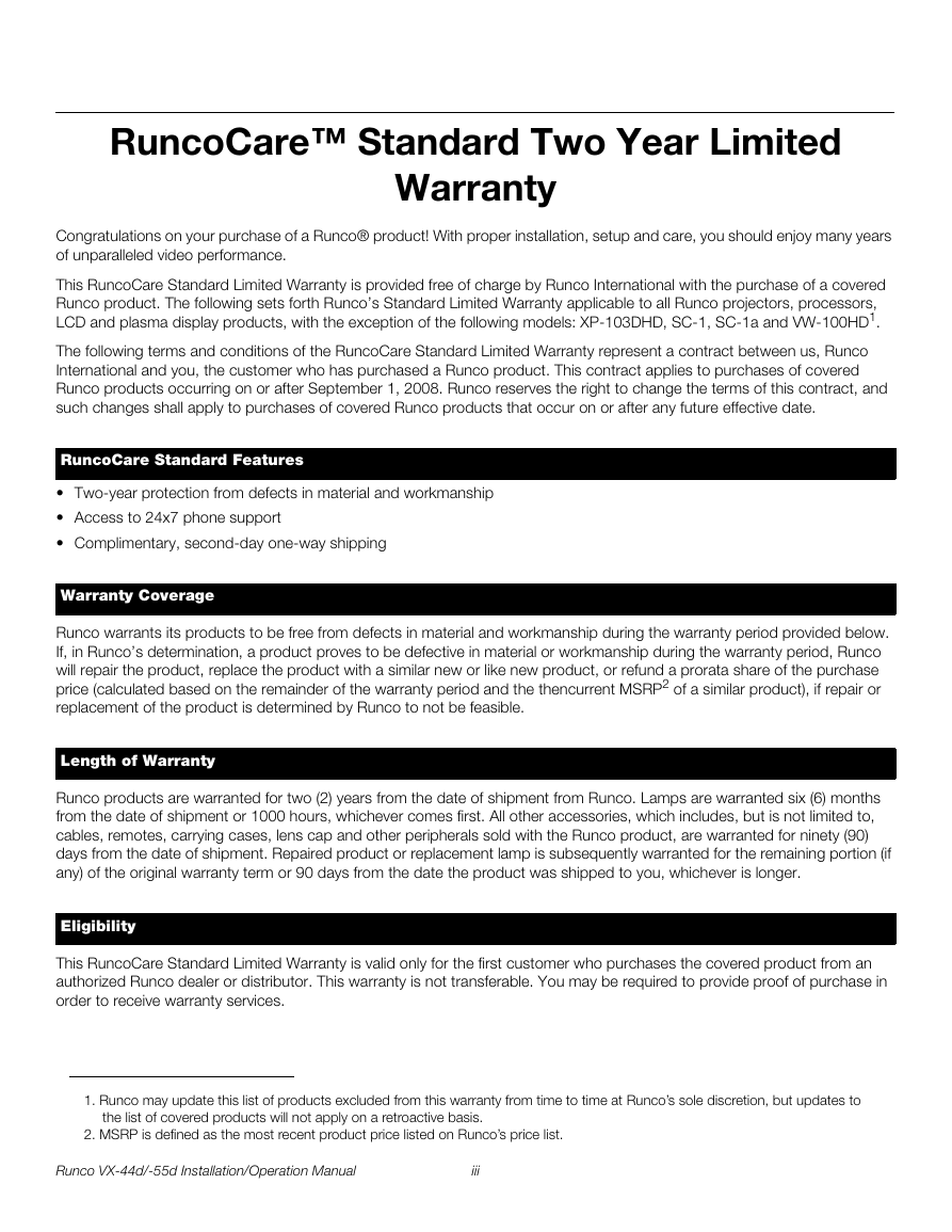
RuncoCare™ Standard Two Year Limited Warranty
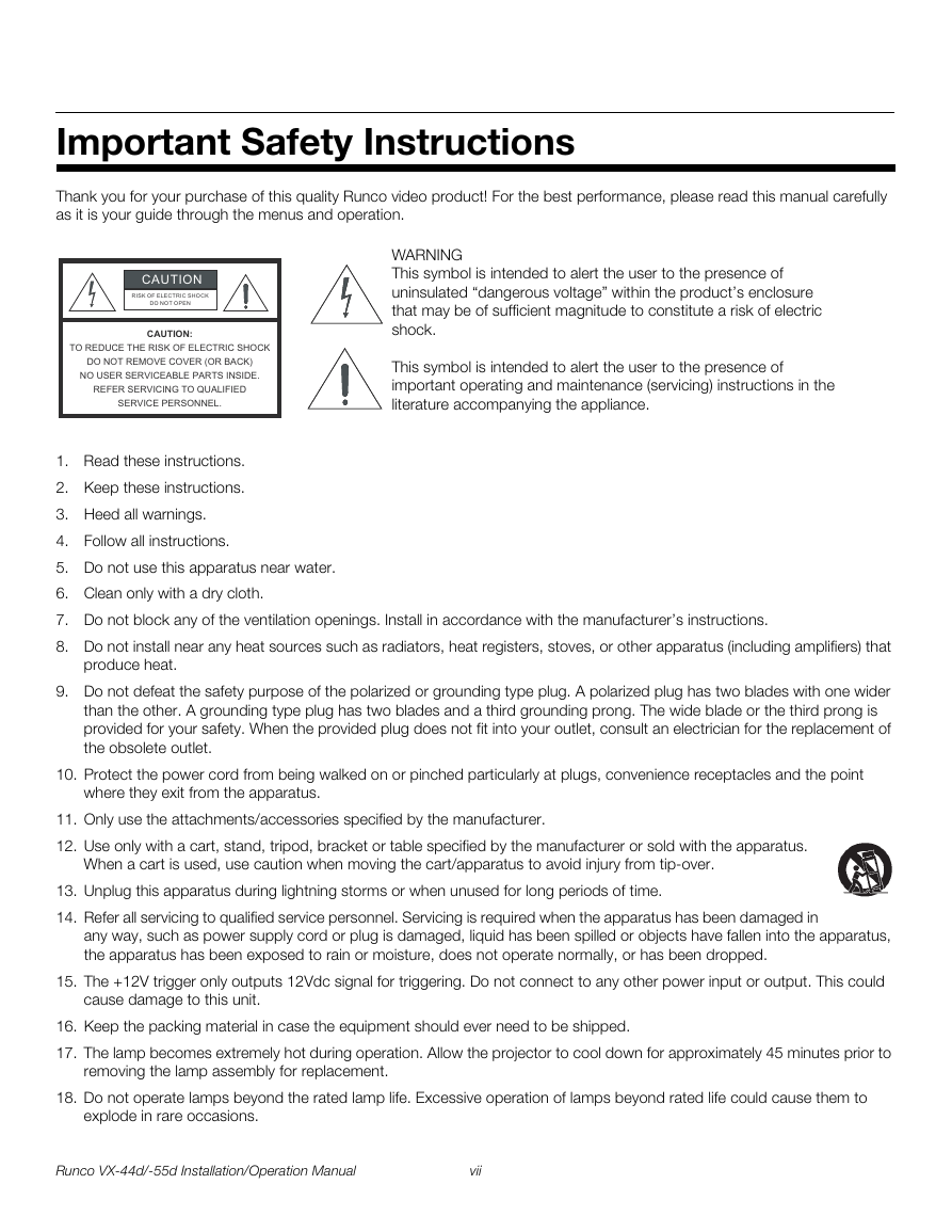
Important Safety Instructions
Compliance Information
1. Introduction
1.1 About This Manual
Target Audience
If You Have Comments About This Manual...
Textual and Graphic Conventions
Text Conventions
Graphic Conventions
1.2 Using This Manual
1.3 Description, Features and Benefits
Key Features and Benefits
Parts List
Optional Accessories
2. Controls and Functions
2.1 VX-44d/-55d at a Glance
Figure 2-1 . VX-44d/-55d Top/Rear/Front View
2.2 VX-44d/-55d Input Panel
Figure 2-2 . VX-44d/-55d Input Panel
2.3 VX-44d/-55d Built-In Keypad
Figure 2-3 . VX-44d/-55d Built-in Keypad
2.4 DHD Controller Front Panel
Figure 2-4 . DHD Controller Front Panel
2.5 DHD Controller Rear Panel
Figure 2-5 . DHD Controller Rear Panel
Outputs
Inputs
2.6 VX-44d/-55d Remote Control Unit
Figure 2-6 . DHD Controller/VX-44d/-55d Remote Control
3. Installation
3.1 Remote Control
Notes on Batteries
Notes on Remote Control Operation
3.2 Quick Setup
Table 3-1 . Installation Overview
3.3 Installation Considerations
Installation Type
Table 3-2 . Projector Installation Options
Ambient Light
Throw Distance
Figure 3-1 . Estimating Throw Distance
Table 3-3 . VX-44d/-55d Lens Options and Throw Ratios
Vertical and Horizontal Position
Figure 3-2 . Projector Placement
Vertical and Horizontal Lens Shift
Figure 3-3 . Vertical Lens Shift (EXAMPLE ONLY)
Figure 3-4 . Horizontal Lens Shift (EXAMPLE ONLY)
Table 3-4 . Vertical and Horizontal Lens Shift Limits
Folded Optics
Figure 3-5 . Folded Optics
Audio/Video Synchronization Issues
Table 3-5 . Possible Audio Latency for Various Input/Output Timings
Other Considerations
3.4 Installing the Projection Lens
Figure 3-6 . Lens Assembly (Front View)
3.5 Installing the Optional CineWide Lens Mount
Remove Projector Front Feet (CineWide with AutoScope)
Install Anamorphic Lens Motor (CineWide with AutoScope) or Base Plate (fixed CineWide)
CineWide with AutoScope
Fixed CineWide
Install Projector Stand (CineWide with AutoScope, Floor-Mount)
3.6 Mounting the VX-44d/-55d
Floor Mounting (Upright)
Ceiling Mounting (Inverted)
Adjusting the Projection Angle
Figure 3-7 . Mounting Angle Ranges (Front-to-Back and Side-to-Side)
3.7 Connections to the VX-44d/-55d and DHD Controller
Connector Panel Access
Connecting the DHD Controller to the VX-44d/-55d
Digital Video Connection
Figure 3-8 . Connecting the VX-44d/-55d to the DHD Controller
RS-232 Connection
Figure 3-9 . RS-232 Connection from the DHD Controller to the VX-44d/-55d
Connecting Source Components to the DHD Controller
HDMI Source Connections
Figure 3-10 . HDMI Source Connections
Component Video Source Connections
Figure 3-11 . Component Video Source Connections
RGBHV Source Connections
Figure 3-12 . RGBHV Source Connections
SCART RGBS Source Connections
Figure 3-13 . SCART RGBS Source Connections
Composite and S-Video Source Connections
Figure 3-14 . S-Video and Composite Video Source Connections
RS-232 Controller Connection
Figure 3-15 . RS-232 Control System Connection
Connecting 12-volt Trigger Outputs to External Equipment
Figure 3-16 . Connecting 12-volt Trigger Outputs
Connecting an External IR Receiver to the DHD Controller
Figure 3-17 . External IR Receiver Connection
Connecting to AC Power
DHD Controller
Projector
AutoScope Lens Motor
3.8 Turning on the Power
3.9 Primary Lens Adjustments
Focus and Zoom
Vertical and Horizontal Lens Shift
3.10 Adjusting the Picture Orientation
3.11 Installing and Adjusting the CineWide Anamorphic Lens
Attach Lens Mounting Assembly to Lens Motor Carriage Plate (CineWide with AutoScope) or Base Plate (fixed CineWide)
Configure Lens Motor Trigger (CineWide with AutoScope)
Adjust the Anamorphic Lens
Horizontal Position (X) Adjustment
Height (Y) Adjustment
Pitch (Angle)
Yaw Adjust
Geometry
Focus
3.12 Optimizing Lamp and Lens Performance
Navigating the Projector Menus
Installation Menu
Calibration and Test Patterns - LumaCal (Lamp Calibration)
OptiCal (Primary Lens Calibration)
3.13 Working With the Lamp
Lamp Hours (read-only)
Lamp S/N (read-only)
Lamp Message
Lamp Limit
Lamp Mode
RVR (Reflectance Volume Regulation)
Lamp History (read-only)
Change Lamp
4. Operation
4.1 Using the On-Screen Menus
Figure 4-1 . DHD Controller OSD Menu Structure for VX-44d/-55d
Main Menu
Input Source
Aspect Ratio
Table 4-1 . Aspect Ratio Settings
Picture
Brightness
Figure 4-2 . Typical PLUGE Pattern for Adjusting Brightness
Contrast
Figure 4-3 . Typical Gray Bar Pattern for Adjusting Contrast
Color Saturation
Figure 4-4 . Typical Color Bar Pattern for Adjusting Color Saturation and Tint
Tint
Sharpness
Figure 4-5 . Typical Test Pattern for Adjusting Sharpness
Noise Filter
Input Position
Left/Right
Up/Down
Width
Height
Overscan/Overscan Mode
Figure 4-6 . Overscan Modes
Phase (RGB, Component or SCART sources)
Tracking (RGB, Component or SCART sources)
Memory Presets
Information
Signal / System
Field Service / Manufacturing
Calibration
Display Color
Figure 4-7 . CIE 1931 Chromaticity Diagram
Table 4-2 . Color Temperature Presets and Associated Color Points
Input Image
Input Color
Save ISF Night/Save ISF Day
Copy/Paste
Output Shift
Splash Configure
OSD Position
Service
Test Video
Input Names
Remote Control
Display Device - Configure
Figure 4-8 . Keystone Correction
Display Device - Auto Calibration
On the VX-44d/-55d Built-in Keypad (see Figure 2-3)
On the DHD Controller Remote Control
What an “Auto Calibration” Does
Color Space
Triggers
Miscellaneous
Sync Threshold
HDMI EDID Extension
Front Panel Brightness
System Reset
5. Maintenance and Troubleshooting
5.1 Lamp and Filter Replacement
Lamp Replacement
Figure 5-1 . Removing the Lamp Door
Figure 5-2 . Unlocking the Lamp
Figure 5-3 . Removing the Lamp
Figure 5-4 . Installing A New Lamp
Filter Replacement
5.2 Lens Replacement
Figure 5-5 . Removing the Primary Lens
5.3 Troubleshooting Tips
Table 5-1 . Troubleshooting Chart
Error Codes
Table 5-2 . VX-44d/-55d Error Codes
6. External Control
6.1 Serial Communications
RS-232 Connection and Port Configuration
Serial Command Syntax
Table 6-1 . Serial Commands
6.2 Using Discrete IR Codes
IR Command Protocol
Figure 6-1 . RC5 Message Format
IR Command List
Table 6-2 . RC5 Control Codes for the DHD Controller
7. Specifications
7.1 VX-44d/-55d Specifications
Table 7-1 . VX-44d/-55d Specifications
7.2 DHD Controller Specifications
Table 7-2 . DHD Controller Specifications
7.3 VX-44d/-55d Dimensions
Figure 7-1 . VX-44d/-55d Dimensions
7.4 Supported Timings
Table 7-3 . Supported Signal Timings by Input



 2023年江西萍乡中考道德与法治真题及答案.doc
 2012年重庆南川中考生物真题及答案.doc
 2013年江西师范大学地理学综合及文艺理论基础考研真题.doc
 2020年四川甘孜小升初语文真题及答案I卷.doc
 2020年注册岩土工程师专业基础考试真题及答案.doc
 2023-2024学年福建省厦门市九年级上学期数学月考试题及答案.doc
 2021-2022学年辽宁省沈阳市大东区九年级上学期语文期末试题及答案.doc
 2022-2023学年北京东城区初三第一学期物理期末试卷及答案.doc
 2018上半年江西教师资格初中地理学科知识与教学能力真题及答案.doc
 2012年河北国家公务员申论考试真题及答案-省级.doc
 2020-2021学年江苏省扬州市江都区邵樊片九年级上学期数学第一次质量检测试题及答案.doc
 2022下半年黑龙江教师资格证中学综合素质真题及答案.doc