Transceiver Macrocell Interface
USB 2.0
(UTMI)
Specification
Version 1.05
3/29/2001
Please send comments via electronic mail to:
steve.mcgowan@intel.com
©1999-2001 Intel Corporation—All rights reserved.
�
USB2.0 Transceiver Macrocell
Intellectual Property Disclaimer
THIS SPECIFICATION IS PROVIDED “AS IS” WITH NO WARRANTIES WHATSOEVER
INCLUDING ANY WARRANTY OF MERCHANTABILITY, FITNESS FOR ANY PARTICULAR
PURPOSE, OR ANY WARRANTY OTHERWISE ARISING OUT OF ANY PROPOSAL,
SPECIFICATION, OR SAMPLE.
INTEL DISCLAIMS ALL LIABILITY, INCLUDING LIABILITY FOR INFRINGEMENT OF
ANY PROPRIETARY RIGHTS, RELATING TO IMPLEMENTATION OF INFORMATION IN
THIS SPECIFICATION. INTEL DOES NOT WARRANT OR REPRESENT THAT SUCH
IMPLEMENTATION(S) WILL NOT INFRINGE SUCH RIGHTS.
A COPYRIGHT LICENSE IS HEREBY GRANTED TO REPRODUCE AND DISTRIBUTE THIS
SPECIFICATION FOR INTERNAL USE ONLY. NO OTHER LICENSE, EXPRESS OR
IMPLIED, BY ESTOPPEL OR OTHERWISE, TO ANY OTHER INTELLECTUAL PROPERTY
RIGHTS IS GRANTED OR INTENDED HEREBY.
AUTHORS OF THIS SPECIFICATION DISCLAIM ALL LIABILITY, INCLUDING LIABILITY
FOR INFRINGEMENT OF PROPRIETARY RIGHTS, RELATING TO IMPLEMENTATION OF
INFORMATION IN THIS SPECIFICATION. AUTHORS OF THIS SPECIFICATION ALSO DO
NOT WARRANT OR REPRESENT THAT SUCH IMPLEMENTATION(S) WILL NOT
INFRINGE SUCH RIGHTS.
ALL SUGGESTIONS TO THIS SPECIFICATION BECOME THE PROPERTY OF INTEL
CORPORATION UPON SUBMISSION.
INTEL MAY MAKE CHANGES TO SPECIFICATIONS, PRODUCT DESCRIPTIONS, AND
PLANS AT ANY TIME, WITHOUT NOTICE.
All product names are trademarks, registered trademarks, or service marks of their respective owners.
Contributors
Jon Lueker
Steve McGowan (Editor)
Ken Oliver
Dean Warren
©1999-2001 Intel Corporation—All rights reserved.
Page 2 of 66
�
USB2.0 Transceiver Macrocell
Table of Contents
4.1
1
2
4.2
4.3
4.4
5.1
1.1
1.2
2.1
2.2
2.3
4.1.1
4.1.2
4.1.3
4.1.4
Preface .................................................................................................................................................... 7
Scope of this Revision..................................................................................................................... 7
Revision History ............................................................................................................................. 7
Introduction............................................................................................................................................. 9
USB 2.0 Transceiver Macrocell (UTM) ......................................................................................... 9
Serial Interface Engine.................................................................................................................. 10
Device Specific Logic................................................................................................................... 10
3
Functional Block Diagram.................................................................................................................... 11
4 UTMI Signal Descriptions.................................................................................................................... 12
System Interface Signals............................................................................................................... 12
CLK ...................................................................................................................................... 13
4.1.1.1 Options.............................................................................................................................. 13
XcvrSelect............................................................................................................................. 13
TermSelect ............................................................................................................................ 13
LineState ............................................................................................................................... 13
4.1.4.1 Synchronization ................................................................................................................ 13
4.1.4.2 Signaling Levels................................................................................................................ 14
4.1.4.3 Minimizing Transitions..................................................................................................... 14
4.1.4.4 Bus Packet Timing............................................................................................................ 15
OpMode ................................................................................................................................ 15
USB Interface Signals................................................................................................................... 15
Vendor Control Signals................................................................................................................. 16
Data Interface Signals ................................................................................................................... 17
Receive Active ...................................................................................................................... 18
5 Block level Descriptions....................................................................................................................... 21
Clock Multiplier............................................................................................................................ 21
Clocking................................................................................................................................ 21
5.1.1.1 HS/FS operation................................................................................................................ 21
5.1.1.2 FS Only operation ............................................................................................................. 22
5.1.1.3 LS Only operation............................................................................................................. 22
5.2
HS DLL (High Speed Delay Line PLL) ....................................................................................... 22
Elasticity Buffer ............................................................................................................................ 22
5.3
5.4 Mux............................................................................................................................................... 22
5.5
NRZI Decoder............................................................................................................................... 23
5.6
Bit Unstuff Logic .......................................................................................................................... 23
Rx Shift/Hold Register.................................................................................................................. 23
5.7
5.8
Receive State Machine.................................................................................................................. 23
Receive Error Reporting ....................................................................................................... 27
5.8.1.1 Bit Suff Error Reporting.................................................................................................... 27
5.9
Rx Shift/Hold Registers ................................................................................................................ 28
5.10 NRZI Encoder............................................................................................................................... 29
5.11 Bitstuff Logic................................................................................................................................ 29
5.12 Tx Shift/Hold Register.................................................................................................................. 29
5.13 Transmit State Machine ................................................................................................................ 30
5.13.1 Transmit Error Reporting...................................................................................................... 31
5.14 USB Full Speed XCVR................................................................................................................. 32
5.14.1 Transmit Driver..................................................................................................................... 32
5.14.2 Receive Buffer ...................................................................................................................... 32
5.15 USB2.0 XCVR.............................................................................................................................. 32
5.15.1 Transmit Driver..................................................................................................................... 32
5.15.2 Receive Buffer ...................................................................................................................... 32
5.15.3 Other Components of Transceiver ........................................................................................ 32
Transmission Envelope Detector .................................................................................. 32
Full-Speed Indicator Control......................................................................................... 32
5.15.3.1
5.15.3.2
4.1.5
4.4.1
5.1.1
5.8.1
©1999-2001 Intel Corporation—All rights reserved.
Page 3 of 66
�
USB2.0 Transceiver Macrocell
5.19.1
5.19.2
5.22.1
5.22.1.1
5.22.1.2
5.22.2.1
5.22.2.2
5.22.2.3
5.16 Operational Modes........................................................................................................................ 33
5.16.1 USB 2.0 Test Mode Generation............................................................................................ 33
5.17 Speed Selection............................................................................................................................. 34
5.18 Bi-directional 8-bit Interface......................................................................................................... 34
5.19 16-Bit Interface ............................................................................................................................. 35
16-Bit Transmit Timing ........................................................................................................ 36
16-Bit Receive Timing.......................................................................................................... 37
5.20 Bi-directional 16-bit Interface....................................................................................................... 38
5.21 Vendor Controls............................................................................................................................ 39
5.22 Other Functions............................................................................................................................. 40
SE0 handling......................................................................................................................... 40
Suspend Detection......................................................................................................... 41
Reset Detection ............................................................................................................. 42
5.22.2 HS Detection Handshake ...................................................................................................... 43
FS Downstream Facing Port ......................................................................................... 45
HS Downstream Facing Port......................................................................................... 46
Suspend Timing ............................................................................................................ 48
5.22.3 Assertion of Resume ............................................................................................................. 50
5.22.4 Detection of Resume............................................................................................................. 51
5.22.5 HS Device Attach.................................................................................................................. 52
6 Appendix............................................................................................................................................... 53
FS Operations................................................................................................................................ 53
FS Start Of Packet................................................................................................................. 53
FS End Of Packet.................................................................................................................. 53
HS Operation ................................................................................................................................ 55
HS Start Of Packet ................................................................................................................ 55
HS End Of Packet ................................................................................................................. 55
Timing Constraints........................................................................................................................ 57
Inter-Packet Delay Overview........................................................................................................ 58
HS Inter-packet delay for a receive followed by a transmit.................................................. 58
HS Inter-packet delay for a receive followed by a receive ................................................... 61
FS Inter-packet delay for a Receive followed by a Transmit................................................ 62
6.4.3.1 HS/FS UTM is running in Full Speed mode ..................................................................... 62
6.4.3.2 FS Only or LS Only UTMs............................................................................................... 63
FS Inter-packet delay for a Transmit followed by a Receive................................................ 63
6.4.4.1 HS/FS UTM is running in Full Speed mode ..................................................................... 63
6.4.4.2 FS Only or LS Only UTMs............................................................................................... 64
6.4.4.3 Full Speed Transmit .......................................................................................................... 64
6.4.4.4 Full Speed Receive............................................................................................................ 65
UTM Entity Diagrams .................................................................................................................. 66
6.1.1
6.1.2
6.2.1
6.2.2
6.4.1
6.4.2
6.4.3
6.1
6.2
6.3
6.4
6.4.4
6.5
©1999-2001 Intel Corporation—All rights reserved.
Page 4 of 66
�
USB2.0 Transceiver Macrocell
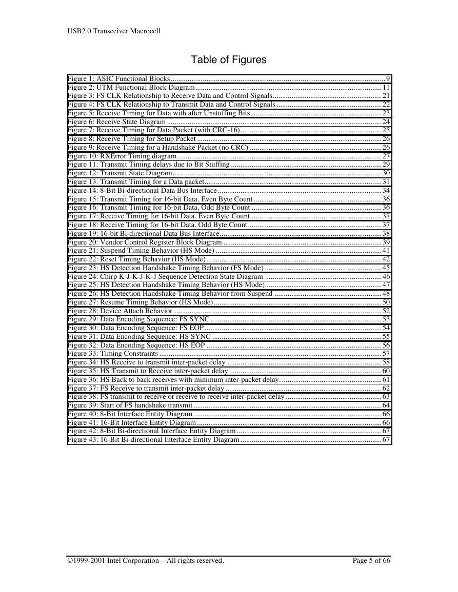
Table of Figures
Figure 1: ASIC Functional Blocks.................................................................................................................. 9
Figure 2: UTM Functional Block Diagram................................................................................................... 11
Figure 3: FS CLK Relationship to Receive Data and Control Signals.......................................................... 21
Figure 4: FS CLK Relationship to Transmit Data and Control Signals........................................................ 22
Figure 5: Receive Timing for Data with after Unstuffing Bits ..................................................................... 23
Figure 6: Receive State Diagram .................................................................................................................. 24
Figure 7: Receive Timing for Data Packet (with CRC-16)........................................................................... 25
Figure 8: Receive Timing for Setup Packet .................................................................................................. 26
Figure 9: Receive Timing for a Handshake Packet (no CRC) ...................................................................... 26
Figure 10: RXError Timing diagram ............................................................................................................ 27
Figure 11: Transmit Timing delays due to Bit Stuffing................................................................................ 29
Figure 12: Transmit State Diagram............................................................................................................... 30
Figure 13: Transmit Timing for a Data packet.............................................................................................. 31
Figure 14: 8-Bit Bi-directional Data Bus Interface....................................................................................... 34
Figure 15: Transmit Timing for 16-bit Data, Even Byte Count.................................................................... 36
Figure 16: Transmit Timing for 16-bit Data, Odd Byte Count ..................................................................... 36
Figure 17: Receive Timing for 16-bit Data, Even Byte Count ..................................................................... 37
Figure 18: Receive Timing for 16-bit Data, Odd Byte Count....................................................................... 37
Figure 19: 16-bit Bi-directional Data Bus Interface...................................................................................... 38
Figure 20: Vendor Control Register Block Diagram .................................................................................... 39
Figure 21: Suspend Timing Behavior (HS Mode) ........................................................................................ 41
Figure 22: Reset Timing Behavior (HS Mode)............................................................................................. 42
Figure 23: HS Detection Handshake Timing Behavior (FS Mode) .............................................................. 45
Figure 24: Chirp K-J-K-J-K-J Sequence Detection State Diagram .............................................................. 46
Figure 25: HS Detection Handshake Timing Behavior (HS Mode).............................................................. 47
Figure 26: HS Detection Handshake Timing Behavior from Suspend ......................................................... 48
Figure 27: Resume Timing Behavior (HS Mode)......................................................................................... 50
Figure 28: Device Attach Behavior .............................................................................................................. 52
Figure 29: Data Encoding Sequence: FS SYNC........................................................................................... 53
Figure 30: Data Encoding Sequence: FS EOP.............................................................................................. 54
Figure 31: Data Encoding Sequence: HS SYNC .......................................................................................... 55
Figure 32: Data Encoding Sequence: HS EOP ............................................................................................. 56
Figure 33: Timing Constraints...................................................................................................................... 57
Figure 34: HS Receive to transmit inter-packet delay .................................................................................. 58
Figure 35: HS Transmit to Receive inter-packet delay................................................................................. 60
Figure 36: HS Back to back receives with minimum inter-packet delay. ..................................................... 61
Figure 37: FS Receive to transmit inter-packet delay................................................................................... 62
Figure 38: FS transmit to receive or receive to receive inter-packet delay................................................... 63
Figure 39: Start of FS handshake transmit.................................................................................................... 64
Figure 40: 8-Bit Interface Entity Diagram.................................................................................................... 66
Figure 41: 16-Bit Interface Entity Diagram.................................................................................................. 66
Figure 42: 8-Bit Bi-directional Interface Entity Diagram............................................................................. 67
Figure 43: 16-Bit Bi-directional Interface Entity Diagram........................................................................... 67
©1999-2001 Intel Corporation—All rights reserved.
Page 5 of 66
�
USB2.0 Transceiver Macrocell
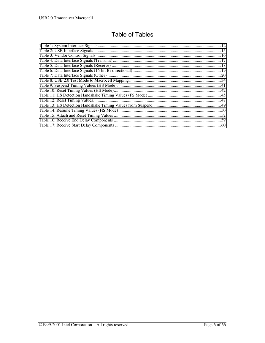
Table of Tables
Table 1: System Interface Signals................................................................................................................. 12
Table 2: USB Interface Signals..................................................................................................................... 15
Table 3: Vendor Control Signals .................................................................................................................. 16
Table 4: Data Interface Signals (Transmit)................................................................................................... 17
Table 5: Data Interface Signals (Receive) .................................................................................................... 18
Table 6: Data Interface Signals (16-bit Bi-directional)................................................................................. 19
Table 7: Data Interface Signals (Other) ........................................................................................................ 20
Table 8: USB 2.0 Test Mode to Macrocell Mapping.................................................................................... 34
Table 9: Suspend Timing Values (HS Mode)............................................................................................... 41
Table 10: Reset Timing Values (HS Mode).................................................................................................. 42
Table 11: HS Detection Handshake Timing Values (FS Mode)................................................................... 45
Table 12: Reset Timing Values..................................................................................................................... 47
Table 13: HS Detection Handshake Timing Values from Suspend .............................................................. 49
Table 14: Resume Timing Values (HS Mode).............................................................................................. 50
Table 15: Attach and Reset Timing Values .................................................................................................. 52
Table 16: Receive End Delay Components .................................................................................................. 59
Table 17: Receive Start Delay Components ................................................................................................. 60
©1999-2001 Intel Corporation—All rights reserved.
Page 6 of 66
�
USB2.0 Transceiver Macrocell
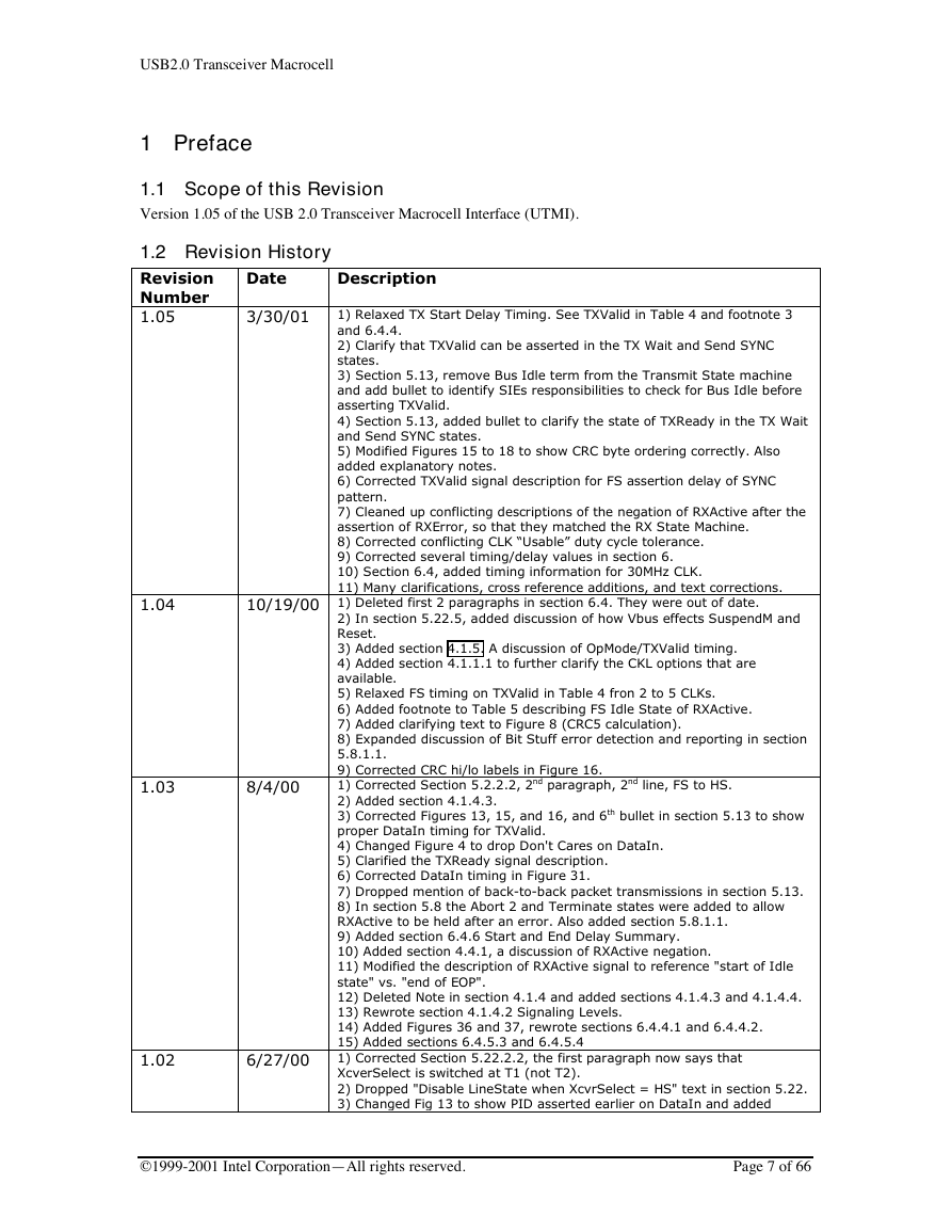
1 Preface
1.1 Scope of this Revision
Version 1.05 of the USB 2.0 Transceiver Macrocell Interface (UTMI).
1.2 Revision History
Revision
Number
1.05
3/30/01
Date
Description
1) Relaxed TX Start Delay Timing. See TXValid in Table 4 and footnote 3
and 6.4.4.
2) Clarify that TXValid can be asserted in the TX Wait and Send SYNC
states.
3) Section 5.13, remove Bus Idle term from the Transmit State machine
and add bullet to identify SIEs responsibilities to check for Bus Idle before
asserting TXValid.
4) Section 5.13, added bullet to clarify the state of TXReady in the TX Wait
and Send SYNC states.
5) Modified Figures 15 to 18 to show CRC byte ordering correctly. Also
added explanatory notes.
6) Corrected TXValid signal description for FS assertion delay of SYNC
pattern.
7) Cleaned up conflicting descriptions of the negation of RXActive after the
assertion of RXError, so that they matched the RX State Machine.
8) Corrected conflicting CLK “Usable” duty cycle tolerance.
9) Corrected several timing/delay values in section 6.
10) Section 6.4, added timing information for 30MHz CLK.
11) Many clarifications, cross reference additions, and text corrections.
1.04
10/19/00 1) Deleted first 2 paragraphs in section 6.4. They were out of date.
2) In section 5.22.5, added discussion of how Vbus effects SuspendM and
Reset.
3) Added section 4.1.5. A discussion of OpMode/TXValid timing.
4) Added section 4.1.1.1 to further clarify the CKL options that are
available.
5) Relaxed FS timing on TXValid in Table 4 fron 2 to 5 CLKs.
6) Added footnote to Table 5 describing FS Idle State of RXActive.
7) Added clarifying text to Figure 8 (CRC5 calculation).
8) Expanded discussion of Bit Stuff error detection and reporting in section
5.8.1.1.
9) Corrected CRC hi/lo labels in Figure 16.
1) Corrected Section 5.2.2.2, 2nd paragraph, 2nd line, FS to HS.
2) Added section 4.1.4.3.
3) Corrected Figures 13, 15, and 16, and 6th bullet in section 5.13 to show
proper DataIn timing for TXValid.
4) Changed Figure 4 to drop Don't Cares on DataIn.
5) Clarified the TXReady signal description.
6) Corrected DataIn timing in Figure 31.
7) Dropped mention of back-to-back packet transmissions in section 5.13.
8) In section 5.8 the Abort 2 and Terminate states were added to allow
RXActive to be held after an error. Also added section 5.8.1.1.
9) Added section 6.4.6 Start and End Delay Summary.
10) Added section 4.4.1, a discussion of RXActive negation.
11) Modified the description of RXActive signal to reference "start of Idle
state" vs. "end of EOP".
12) Deleted Note in section 4.1.4 and added sections 4.1.4.3 and 4.1.4.4.
13) Rewrote section 4.1.4.2 Signaling Levels.
14) Added Figures 36 and 37, rewrote sections 6.4.4.1 and 6.4.4.2.
15) Added sections 6.4.5.3 and 6.4.5.4
1) Corrected Section 5.22.2.2, the first paragraph now says that
XcverSelect is switched at T1 (not T2).
2) Dropped "Disable LineState when XcvrSelect = HS" text in section 5.22.
3) Changed Fig 13 to show PID asserted earlier on DataIn and added
1.03
8/4/00
1.02
6/27/00
©1999-2001 Intel Corporation—All rights reserved.
Page 7 of 66
�
USB2.0 Transceiver Macrocell
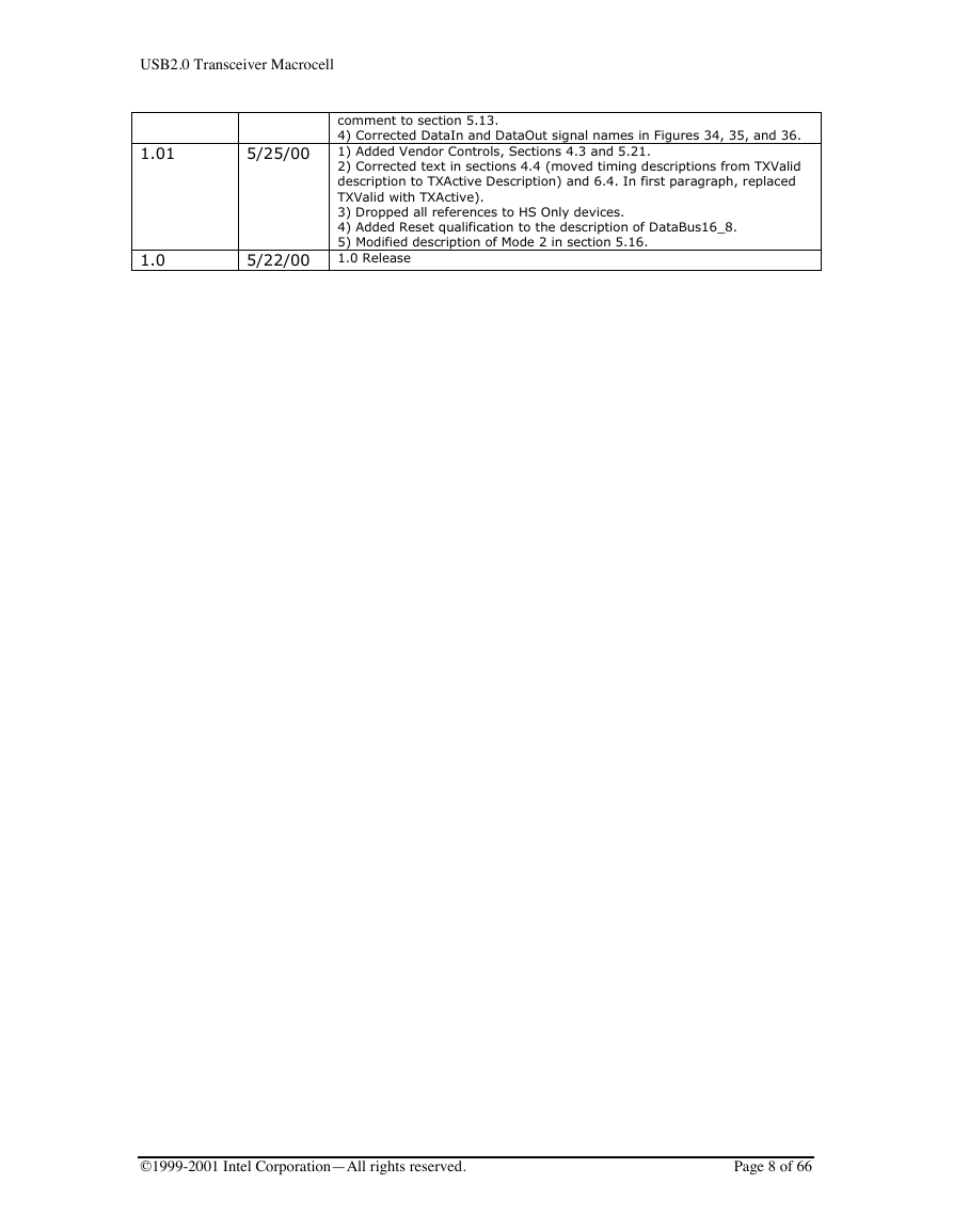
1.01
5/25/00
1.0
5/22/00
comment to section 5.13.
4) Corrected DataIn and DataOut signal names in Figures 34, 35, and 36.
1) Added Vendor Controls, Sections 4.3 and 5.21.
2) Corrected text in sections 4.4 (moved timing descriptions from TXValid
description to TXActive Description) and 6.4. In first paragraph, replaced
TXValid with TXActive).
3) Dropped all references to HS Only devices.
4) Added Reset qualification to the description of DataBus16_8.
5) Modified description of Mode 2 in section 5.16.
1.0 Release
©1999-2001 Intel Corporation—All rights reserved.
Page 8 of 66
�


 2023年江西萍乡中考道德与法治真题及答案.doc
 2012年重庆南川中考生物真题及答案.doc
 2013年江西师范大学地理学综合及文艺理论基础考研真题.doc
 2020年四川甘孜小升初语文真题及答案I卷.doc
 2020年注册岩土工程师专业基础考试真题及答案.doc
 2023-2024学年福建省厦门市九年级上学期数学月考试题及答案.doc
 2021-2022学年辽宁省沈阳市大东区九年级上学期语文期末试题及答案.doc
 2022-2023学年北京东城区初三第一学期物理期末试卷及答案.doc
 2018上半年江西教师资格初中地理学科知识与教学能力真题及答案.doc
 2012年河北国家公务员申论考试真题及答案-省级.doc
 2020-2021学年江苏省扬州市江都区邵樊片九年级上学期数学第一次质量检测试题及答案.doc
 2022下半年黑龙江教师资格证中学综合素质真题及答案.doc