1. Overview
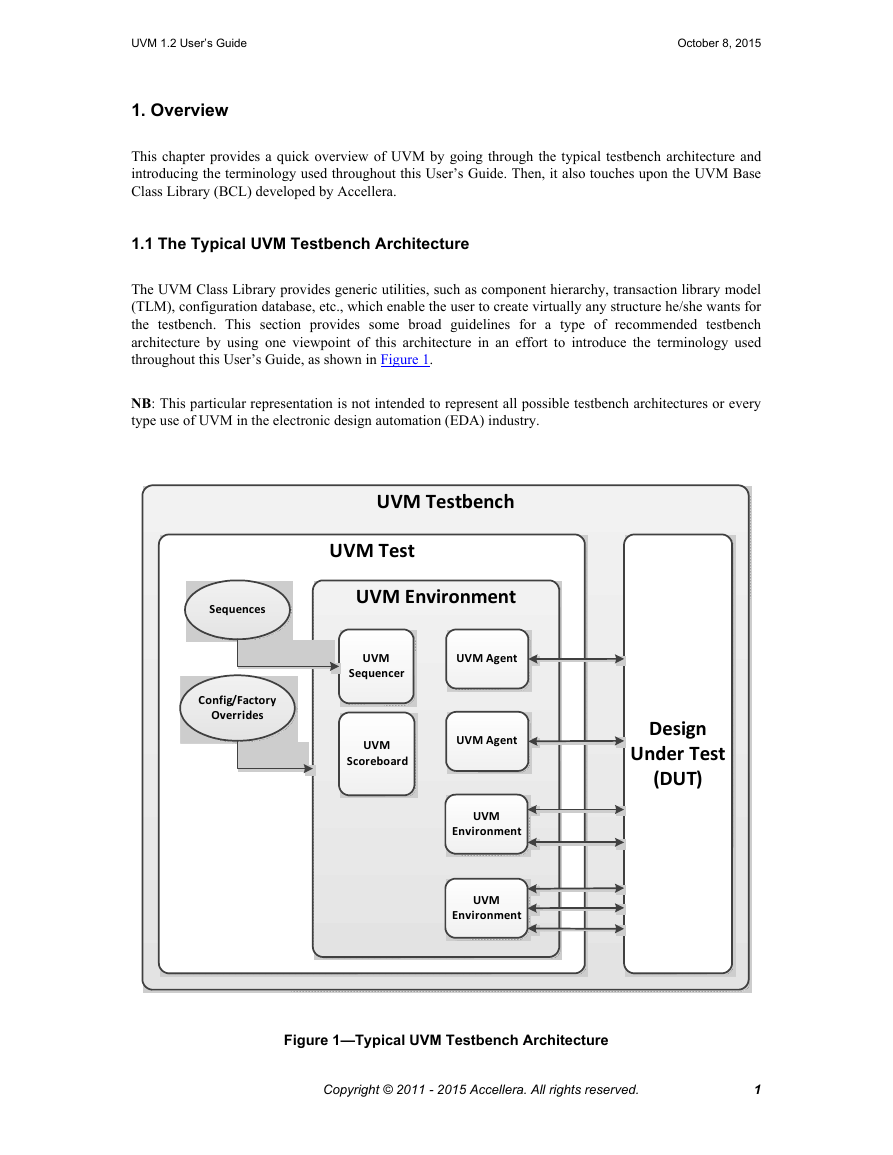
1.1 The Typical UVM Testbench Architecture
1.1.1 UVM Testbench
1.1.2 UVM Test
1.1.3 UVM Environment
1.1.4 UVM Scoreboard
1.1.5 UVM Agent
1.1.6 UVM Sequencer
1.1.7 UVM Sequence
1.1.8 UVM Driver
1.1.9 UVM Monitor
1.2 The UVM Class Library
2. Transaction-Level Modeling (TLM)
2.1 Overview
2.2 TLM, TLM-1, and TLM-2.0
2.3 TLM-1 Implementation
2.3.1 Basics
2.3.2 Encapsulation and Hierarchy
2.3.3 Analysis Communication
2.4 TLM-2.0 Implementation
2.4.1 Generic Payload
2.4.2 Core Interfaces and Ports
2.4.3 Blocking Transport
2.4.4 Nonblocking Transport
2.4.5 Sockets
2.4.6 Time
2.4.7 Use Models
3. Developing Reusable Verification Components
3.1 Modeling Data Items for Generation
3.1.1 Inheritance and Constraint Layering
3.1.2 Defining Control Fields (“Knobs”)
3.2 Transaction-Level Components
3.3 Creating the Driver
3.4 Creating the Sequencer
3.5 Connecting the Driver and Sequencer
3.5.1 Basic Sequencer and Driver Interaction
3.5.2 Querying for the Randomized Item
3.5.3 Fetching Consecutive Randomized Items
3.5.4 Sending Processed Data back to the Sequencer
3.5.5 Using TLM-Based Drivers
3.6 Creating the Monitor
3.7 Instantiating Components
3.8 Creating the Agent
3.8.1 Operating Modes
3.8.2 Connecting Components
3.9 Creating the Environment
3.9.1 The Environment Class
3.9.2 Invoking build_phase
3.10 Enabling Scenario Creation
3.10.1 Declaring User-Defined Sequences
3.10.2 Sending Subsequences and Sequence Items
3.10.3 Starting a Sequence on a Sequencer
3.10.4 Overriding Sequence Items and Sequences
3.11 Managing End of Test
3.12 Implementing Checks and Coverage
3.12.1 Implementing Checks and Coverage in Classes
3.12.2 Implementing Checks and Coverage in Interfaces
3.12.3 Controlling Checks and Coverage
4. Using Verification Components
4.1 Creating a Top-Level Environment
4.2 Instantiating Verification Components
4.3 Creating Test Classes
4.4 Verification Component Configuration
4.4.1 Verification Component Configurable Parameters
4.4.2 Verification Component Configuration Mechanism
4.4.3 Choosing between uvm_resource_db and uvm_config_db
4.4.4 Using a Configuration Class
4.5 Creating and Selecting a User-Defined Test
4.5.1 Creating the Base Test
4.5.2 Creating Tests from a Test-Family Base Class
4.5.3 Test Selection
4.6 Creating Meaningful Tests
4.6.1 Constraining Data Items
4.6.2 Data Item Definitions
4.6.3 Creating a Test-Specific Frame
4.7 Virtual Sequences
4.7.1 Creating a Virtual Sequencer
4.7.2 Creating a Virtual Sequence
4.7.3 Controlling Other Sequencers
4.7.4 Connecting a Virtual Sequencer to Subsequencers
4.8 Checking for DUT Correctness
4.9 Scoreboards
4.9.1 Creating the Scoreboard
4.9.2 Adding Exports to uvm_scoreboard
4.9.3 Requirements of the TLM Implementation
4.9.4 Defining the Action Taken
4.9.5 Adding the Scoreboard to the Environment
4.9.6 Summary
4.10 Implementing a Coverage Model
4.10.1 Selecting a Coverage Method
4.10.2 Implementing a Functional Coverage Model
4.10.3 Enabling and Disabling Coverage
5. Using the Register Layer Classes
5.1 Overview
5.2 Usage Model
5.2.1 Sub-register Access
5.2.2 Mirroring
5.2.3 Memories are not Mirrored
5.3 Access API
5.3.1 read / write
5.3.2 peek / poke
5.3.3 get / set
5.3.4 randomize
5.3.5 update
5.3.6 mirror
5.3.7 Concurrent Accesses
5.4 Coverage Models
5.4.1 Predefined Coverage Identifiers
5.4.2 Controlling Coverage Model Construction and Sampling
5.5 Constructing a Register Model
5.5.1 Field Types
5.5.2 Register Types
5.5.3 Register File Types
5.5.4 Memory Types
5.5.5 Block Types
5.5.6 Packaging a Register Model
5.5.7 Maximum Data Size
5.6 Back-door Access
5.6.1 Back-door read/write vs. peek/poke
5.6.2 Hierarchical HDL Paths
5.6.3 VPI-based Back-door Access
5.6.4 User-defined Back-door Access
5.6.5 Back-door Access for Protected Memories
5.6.6 Active Monitoring
5.7 Special Registers
5.7.1 Pre-defined Special Registers
5.7.2 Unmapped Registers and Memories
5.7.3 Aliased Registers
5.7.4 Unimplemented Registers
5.7.5 RO and WO Registers Sharing the Same Address
5.8 Integrating a Register Model in a Verification Environment
5.9 Integrating a Register Model
5.9.1 Transaction Adapter
5.9.2 Integrating Bus Sequencers
5.9.3 Integrating the Register Model with a Bus Monitor
5.10 Randomizing Field Values
5.11 Pre-defined Sequences
6. Advanced Topics
6.1 The uvm_component Base Class
6.2 The Built-In Factory and Overrides
6.2.1 About the Factory
6.2.2 Factory Registration
6.2.3 Component Overrides
6.3 Callbacks
6.3.1 Use Model
6.3.2 Example
6.4 The Sequence Library
6.5 Advanced Sequence Control
6.5.1 Implementing Complex Scenarios
6.5.2 Protocol Layering
6.5.3 Generating the Item or Sequence in Advance
6.5.4 Executing Sequences and Items on other Sequencers
6.6 Command Line Interface (CLI)
6.6.1 Introduction
6.6.2 Getting Started
6.6.3 UVM-aware Command Line Processing
6.7 Macros in UVM
7. UBus Verification Component Example
7.1 UBus Example
7.2 UBus Example Architecture
7.3 UBus Top Module
7.4 The Test
7.5 Testbench Environment
7.6 UBus Environment
7.7 UBus Master Agent
7.8 UBus Master Sequencer
7.9 UBus Driver
7.10 UBus Agent Monitor
7.11 UBus Bus Monitor
7.11.1 Collecting Transfers from the Bus
7.11.2 Number of Transfers
7.11.3 Notifiers Emitted by the UBus Bus Monitor
7.11.4 Checks and Coverage
7.12 UBus Interface
8. UBus Specification
8.1 Introduction
8.1.1 Motivation
8.1.2 Bus Overview
8.2 Bus Description
8.2.1 Bus Signals
8.2.2 Clocking
8.2.3 Reset
8.3 Arbitration Phase
8.4 Address Phase
8.4.1 NOP Cycle
8.4.2 Normal Address Phase
8.5 Data Phase
8.5.1 Write Transfer
8.5.2 Error during Write Transfer
8.5.3 Read Transfer
8.5.4 Error during Read Transfer
8.6 How Data is Driven
8.7 Optional Pipelining Scheme
8.7.1 Pipelined Arbitration Phase
8.7.2 Pipelined Address Phase
8.7.3 Pipelined Data Phase
8.8 Example Timing Diagrams




 2023年江西萍乡中考道德与法治真题及答案.doc
 2012年重庆南川中考生物真题及答案.doc
 2013年江西师范大学地理学综合及文艺理论基础考研真题.doc
 2020年四川甘孜小升初语文真题及答案I卷.doc
 2020年注册岩土工程师专业基础考试真题及答案.doc
 2023-2024学年福建省厦门市九年级上学期数学月考试题及答案.doc
 2021-2022学年辽宁省沈阳市大东区九年级上学期语文期末试题及答案.doc
 2022-2023学年北京东城区初三第一学期物理期末试卷及答案.doc
 2018上半年江西教师资格初中地理学科知识与教学能力真题及答案.doc
 2012年河北国家公务员申论考试真题及答案-省级.doc
 2020-2021学年江苏省扬州市江都区邵樊片九年级上学期数学第一次质量检测试题及答案.doc
 2022下半年黑龙江教师资格证中学综合素质真题及答案.doc