About This Guide
Overview of Creo Object TOOLKIT C++
Setting Up Creo Object TOOLKIT C++
Installing Creo Object TOOLKIT C++
Building a Sample Application
Licensing Options for Creo Object TOOLKIT C++
Unlocking the Creo Object TOOLKIT C++ Application
Digitally Signing the Application
Unlock Messages
How Creo Object TOOLKIT C++ Works
Domains of Creo Object TOOLKIT C++
Casting of Creo Object TOOLKIT C++ pfc Classes to wfc Classes
Categories of Creo Object TOOLKIT C++ Classes
List of Classes and Methods
Creo-Related Interfaces
Initialization, Smart Pointers, and Memory Management
Attributes
Methods
Inheritance
Exceptions
Compact Data Classes
Initialization
Attributes
Methods
Inheritance
Exceptions
Union Classes
Sequence Classes
Initialization
Attributes
Methods
Inheritance
Exceptions
Example Code: Sequence Class
Array Classes
Initialization
Attributes
Methods
Inheritance
Exceptions
Enumeration Classes
Sharing Enumerations and Constants with Creo Parametric TOOLKIT
Action Listener Classes
Initialization
Attributes
Methods
Inheritance
Exceptions
Example Code: Listener Class
Utilities
Initialization
Attributes
Methods
Inheritance
Exceptions
Sample Utility Class
Creo Object TOOLKIT C++ Support for Creo
Support for Multi-CAD Models Using Creo Unite
Using Creo Object TOOLKIT C++ with Creo Parametric TOOLKIT
Migrating Creo Parametric TOOLKIT Applications to Creo Object TOOLKIT C++ Using Tools
Creating Applications
Application Hierarchy
Exception Handling
Cip Exceptions
PFC/WFC Exceptions
Creo Parametric TOOLKIT Errors
Approaches to Creo Object TOOLKIT C++ Exception Handling
Version Compatibility: Creo Parametric and Creo Object TOOLKIT C++
Retrieving Creo Datecode
Compatibility of Deprecated Methods
Visit Methods
The Creo Object TOOLKIT C++ Online Browser
Online Documentation for Creo Object TOOLKIT C++ APIWizard
Installing the APIWizard
APIWizard Overview
Non-Applet APIWizard Top Page
User’s Guide
Session Objects
Overview of Session Objects
Getting the Session Object
Getting Session Information
Creo License Data
Directories
File Handling
Configuration Options
Registry File Data
Macros
Execution Rules
Colors and Line Styles
Initializing Objects
Accessing the Creo User Interface
The Text Message File
Restrictions on the Text Message File
Contents of the Message File
Writing a Message Using a Message Pop-up Dialog Box
Accessing the Message Window
Writing Messages to the Message Window
Writing Messages to an Internal Buffer
Message Classification
Reading Data from the Message Window
Displaying Feature Parameters
File Dialogs
Customizing the Creo Navigation Area
Adding Custom Web Pages
Selection
Interactive Selection
Accessing Selection Data
Controlling Selection Display
Programmatic Selection
Selection Buffer
Introduction to Selection Buffers
Reading the Contents of the Selection Buffer
Removing the Items of the Selection Buffer
Adding Items to the Selection Buffer
Ribbon Tabs, Groups, and Menu Items
Creating Ribbon Tabs, Groups, and Menu Items
Workflow to Add Menu Items to the Ribbon User Interface
About the Ribbon Definition File
To Specify the Path for the Ribbon Definition File
Loading Multiple Applications Using the Ribbon Definition File
Localizing the Ribbon User Interface Created by the Creo Object TOOLKIT C++ Applications
Menus, Commands, and Pop-up Menus
Introduction
Menu Bar Definitions
Menu Buttons and Menus
Finding Creo Parametric Commands
Access Listeners for Commands
Bracket Listeners for Commands
Designating Commands
Command Icons
Designating the Command
Placing the Button
Pop-up Menus
Adding a Pop-up Menu to the Graphics Window
Using the Trail File to Determine Existing Pop-up Menu Names
Listening for Pop-up Menu Initialization
Accessing the Pop-up Menus
Adding Content to the Pop-up Menus
User Interface Foundation Classes for Dialogs
Introduction
Models
Overview of Model Objects
Getting a Model Object
Model Descriptors
Retrieving Models
Model Information
Model Operations
Running Creo Modelcheck
Custom Checks
Registering Custom Checks
Custom Check Listeners
Notebook
Drawings
Overview of Drawings in Creo Object TOOLKIT C++
Creating Drawings from Templates
Drawing Creation Errors
Obtaining Drawing Models
Drawing Information
Access Drawing Location in Grid
Drawing Tree
Drawing Operations
Merge Drawings
Drawing Sheets
Drawing Sheet Information
Drawing Sheet Operations
Drawing Format Files
Drawing Views
Creating Drawing Views
General Drawing Views
Projected Drawing Views
Obtaining Drawing Views
Drawing View Information
Drawing View Display Information
Drawing Views Operations
Drawing Dimensions
Obtaining Drawing Dimensions
Creating Drawing Dimensions
Drawing Dimensions Information
Drawing Dimensions Operations
Ordinate Dimensions
Drawing Tables
Creating Drawing Cells
Selecting Drawing Tables and Cells
Creating Drawing Tables
Retrieving Drawing Tables
Drawing Tables Information
Drawing Tables Operations
Drawing Table Segments
Repeat Regions
Drawing Views And Models
Listing Drawing Views
Modifying Views
Detailed Views
Auxiliary Views
Revolved Views
View Orientation
Sections of a View
Visible Areas of Views
View States
Drawing Models
Drawing Edges
Detail Items
Listing Detail Items
Creating, Modifying and Reading Detail Items
Detail Note Data
Cross-referencing 3D Notes and Drawing Annotations
Symbol Definition Attachments
Symbol Instance Data
Cross-referencing Weld Symbols and Drawing Annotations
Detail Group Data
Drawing Symbol Groups
Manipulating Symbol Groups
Detail Entities
Instructions
Detail Entities Information
Detail Entities Operations
OLE Objects
Detail Notes
Instructions
Detail Notes Information
Details Notes Operations
Detail Groups
Instructions
Detail Groups Information
Detail Groups Operations
Detail Symbols
Detail Symbol Definitions
Instructions
Detail Symbol Definitions Information
Detail Symbol Definitions Operations
Retrieving Symbol Definitions
Detail Symbol Instances
Instructions
Detail Symbol Instances Information
Detail Symbol Instances Operations
Detail Symbol Groups
Instructions
Detail Symbol Group Information
Detail Symbol Group Operations
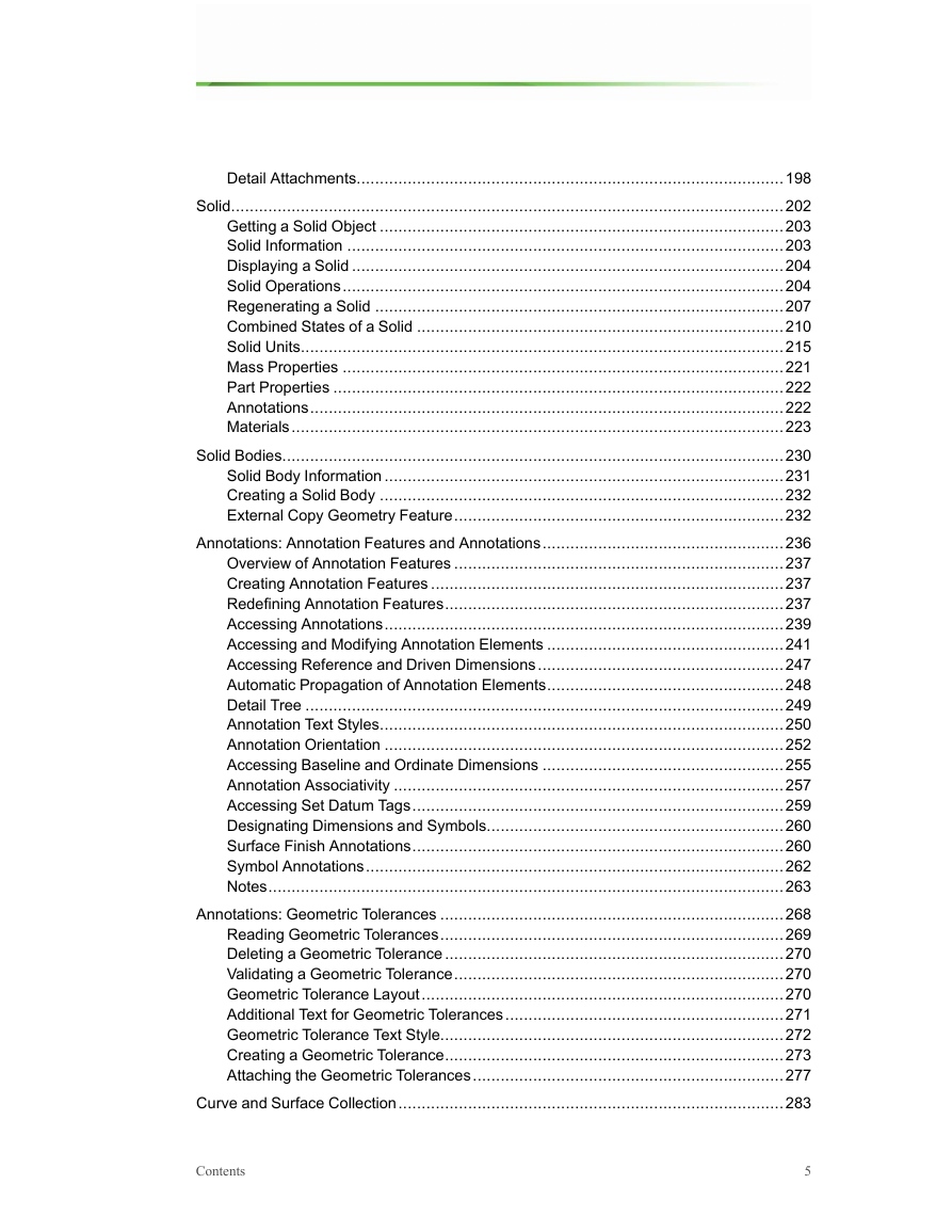
Detail Attachments
Free Attachment
Parametric Attachment
Offset Attachment
Unsupported Attachment
Solid
Getting a Solid Object
Solid Information
Displaying a Solid
Solid Operations
Regenerating a Solid
Combined States of a Solid
Solid Units
Types of Unit Systems
Accessing Individual Units
Modifying Individual Units
Creating a New Unit
Accessing Systems of Units
Modifying Systems of Units
Creating a New System of Units
Conversion to a New Unit System
Mass Properties
Part Properties
Annotations
Materials
Accessing Material Types
Accessing Material Properties
Accessing User-defined Material Properties
Solid Bodies
Solid Body Information
Creating a Solid Body
External Copy Geometry Feature
To create a multibody part from an assembly
Example 1: Creating a multibody part from an assembly
To create an assembly from a multibody part
Example 2: Creating an assembly from a multibody part
To set the appearance of bodies
Example 3: Identifying bodies or applying appearance to bodies
Annotations: Annotation Features and Annotations
Overview of Annotation Features
Creating Annotation Features
Redefining Annotation Features
Accessing Annotations
Accessing and Modifying Annotation Elements
Accessing Reference and Driven Dimensions
Automatic Propagation of Annotation Elements
Detail Tree
Annotation Text Styles
Annotation Orientation
Accessing Baseline and Ordinate Dimensions
Baseline Dimensions
Ordinate Dimensions
Annotation Associativity
Accessing Set Datum Tags
Designating Dimensions and Symbols
Surface Finish Annotations
Symbol Annotations
Creating, Reading and Modifying 3D Symbols
Locating and Collecting 3D Symbols and Symbol Definitions
Notes
Note Properties
Accessing Note Placement
Modifying 3D Note Attachments
Text Style Properties
Annotations: Geometric Tolerances
Reading Geometric Tolerances
Deleting a Geometric Tolerance
Validating a Geometric Tolerance
Geometric Tolerance Layout
Additional Text for Geometric Tolerances
Geometric Tolerance Text Style
Creating a Geometric Tolerance
Attaching the Geometric Tolerances
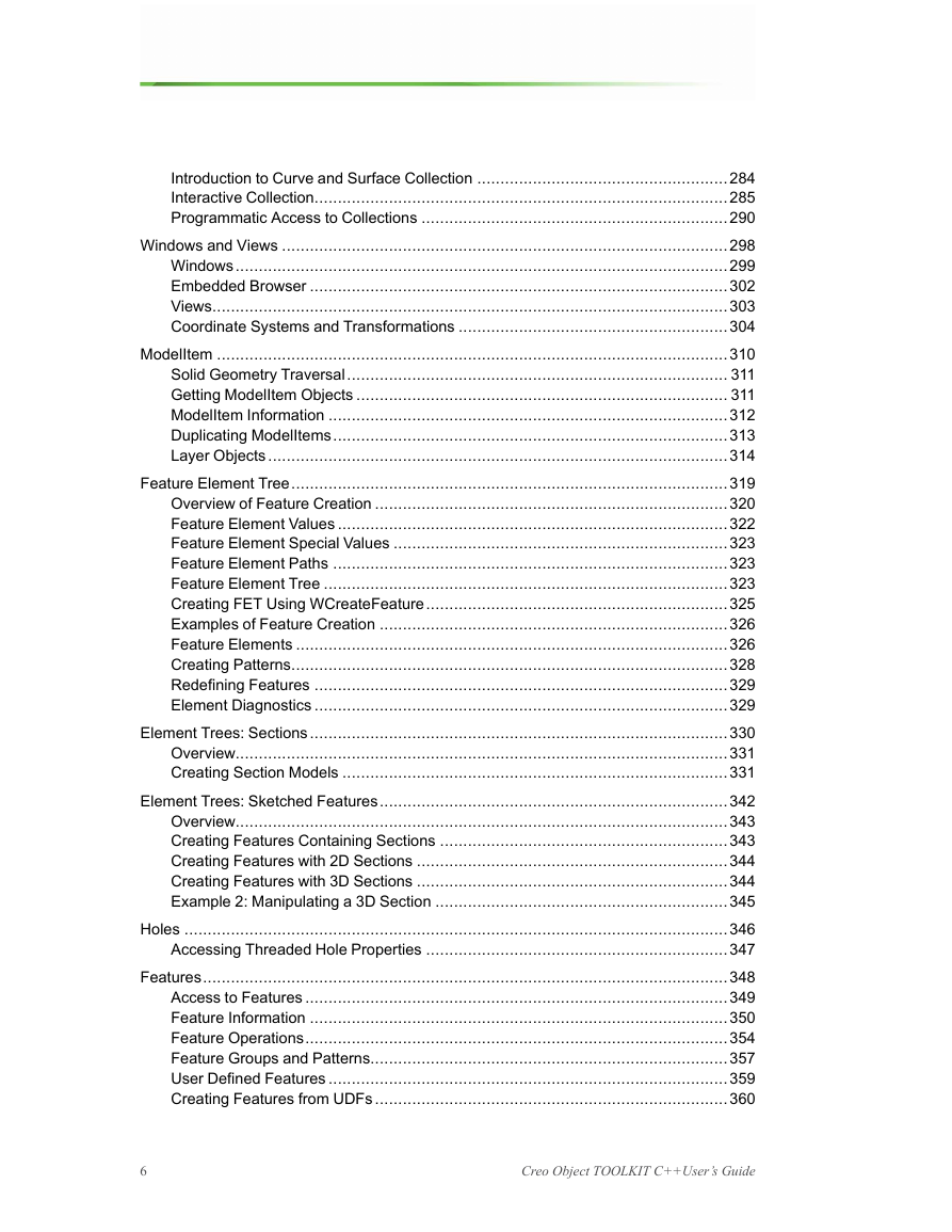
Curve and Surface Collection
Introduction to Curve and Surface Collection
Interactive Collection
Programmatic Access to Collections
The wfcCollection Interface
Curve Collection
Surface Collection
Windows and Views
Windows
Getting a Window Object
Creating Windows
Window Operations
Embedded Browser
Views
Getting a View Object
View Operations
Coordinate Systems and Transformations
Coordinate Systems
Solid Coordinate System
Screen Coordinate System
Window Coordinate System
Drawing Coordinate System
Drawing View Coordinate System
Assembly Coordinate System
Datum Coordinate System
Section Coordinate System
Transformations
Transforming to Screen Coordinates
Transforming to Coordinate System Datum Coordinates
Transforming Window Coordinates
Transforming Coordinates of an Assembly Member
ModelItem
Solid Geometry Traversal
Getting ModelItem Objects
ModelItem Information
Duplicating ModelItems
Layer Objects
Getting Layer Objects
Layer Operations
Layer State
Feature Element Tree
Overview of Feature Creation
Element Tree Types
Building Features Using Element Trees
Feature Element Values
Feature Element Special Values
Feature Element Paths
Feature Element Tree
Creating FET Using WCreateFeature
Examples of Feature Creation
Feature Elements
Creating Patterns
Redefining Features
Element Diagnostics
Element Trees: Sections
Overview
Creating Section Models
Setting the Intent Manager Mode of a Section
Example 1: Creating a Section Model
To Create and Save a Section Model
Allocating a Two-Dimensional Section
Copying the Current Section
Epsilon Value in Sections
Section Entities
Section Entity Arc
Section Entity Blend Vertex
Section Entity Coordinate System
Section Entity CenterLine
Section Entity Circle
Section Entity Ellipse
Section Entity Conic
Section Entity Line
Section Entity Point
Section Entity Polyline
Section Entity Spline
Section Entity Text
Retrieving a Section
Element Trees: Sketched Features
Overview
Creating Features Containing Sections
To Create Sketched Features Element Trees
Example 1: Creating a Sweep Feature
Creating Features with 2D Sections
Creating Features with 3D Sections
3D Section Location in the Owning Model
Example 2: Manipulating a 3D Section
Holes
Accessing Threaded Hole Properties
Features
Access to Features
Feature Information
Feature Inquiry
Feature Operations
Feature Groups and Patterns
User Defined Features
Read Access to Groups and User Defined Features
Creating Features from UDFs
Creating UDFs
Creating Interactively Defined UDFs
Creating a Custom UDF
Setting the Family Table Instance Name
Setting Dependency Type
Setting Scale and Scale Type
Setting the Appearance of the Non UDF Dimensions
Setting the Variable Dimensions and Parameters
Setting the User Defined References
Setting the Assembly Intersections
External Symbol: Parameters
External Symbol: Dimensions
Setting Orientations
Setting Quadrants
Setting the External References
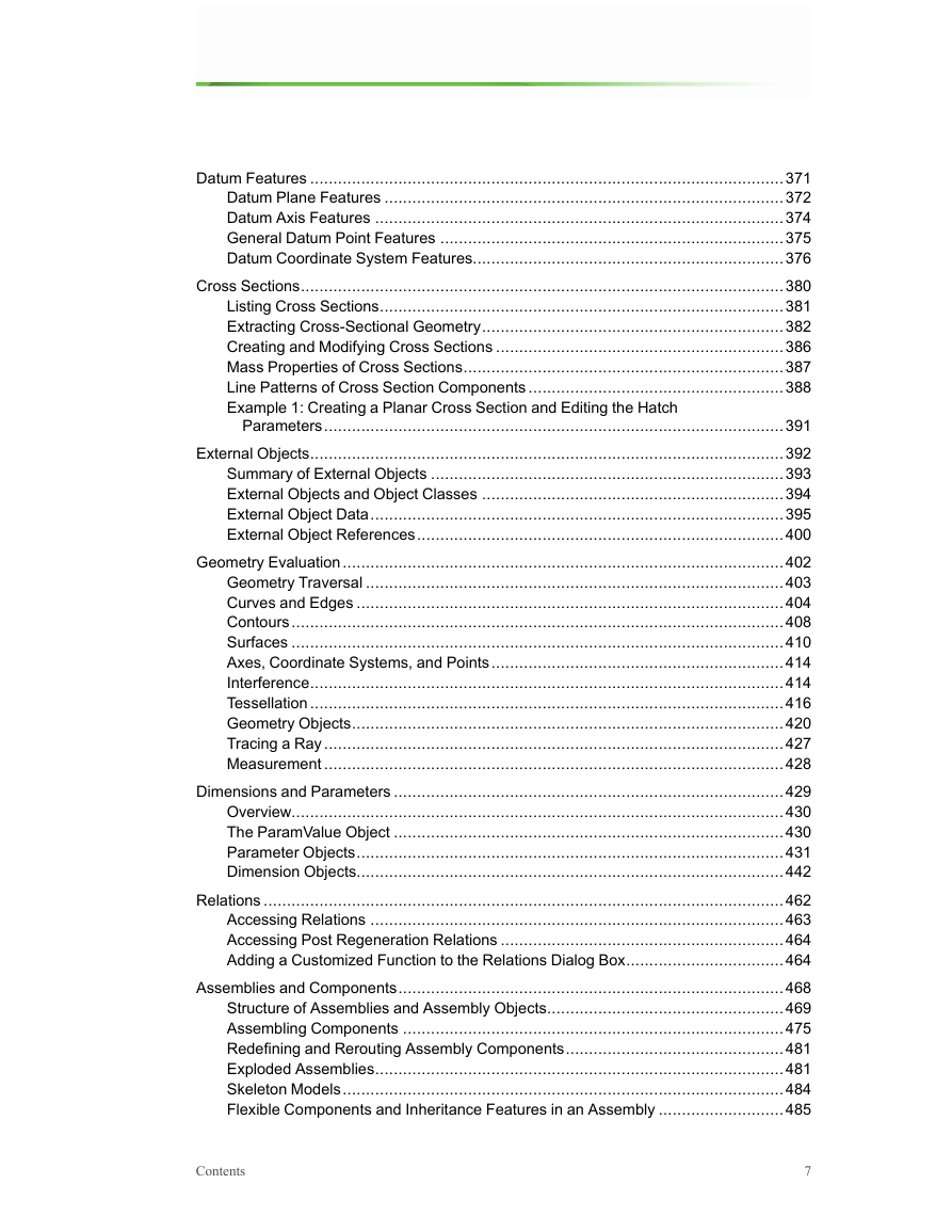
Datum Features
Datum Plane Features
Datum Axis Features
General Datum Point Features
Datum Coordinate System Features
Cross Sections
Listing Cross Sections
Extracting Cross-Sectional Geometry
Creating and Modifying Cross Sections
Mass Properties of Cross Sections
Line Patterns of Cross Section Components
Example 1: Creating a Planar Cross Section and Editing the Hatch Parameters
External Objects
Summary of External Objects
External Objects and Object Classes
Creating External Objects
External Object Owners
External Object Data
Display Data for External Objects
Creating the External Object Entity
External Object Display Properties
External Object Color
Line Styles for External Objects
External Object Scale
Transformation of the External Object
Selection Data for External Objects
Manipulating External Object Data
External Object References
Creating External Object References
Geometry Evaluation
Geometry Traversal
Geometry Terms
Traversing the Geometry of a Solid Block
Curves and Edges
The t Parameter
Curve and Edge Types
Composite Curves
Evaluation of Curves and Edges
Solid Edge Geometry
Curve Descriptors
Contours
Surfaces
UV Parameterization
Surface Types
Surface Information
Evaluation of Surfaces
Surface Descriptors
Axes, Coordinate Systems, and Points
Evaluation of ModelItems
Interference
Analyzing Interference Information
Analyzing Interference Volume
Tessellation
Surface Tessellation
Curve and Edge Tessellation
Part and Assembly Tessellation
Geometry Objects
Geometry of Points
Geometry of Coordinate System Datums
Geometry of Solid Edges
Geometry of Quilts
Geometry of Surfaces
Geometry of datums
Tracing a Ray
Measurement
Dimensions and Parameters
Overview
The ParamValue Object
Accessing a ParamValue Object
Accessing the ParamValue Value
Parameter Objects
Creating and Accessing Parameters
Parameter Selection Options
Parameter Information
Parameter Restrictions
Enumeration Restriction
Range Restriction
Table Parameters
Driven and Driving Parameters
Dimension Objects
Getting Dimensions
Dimension Information
Modifying Dimensions
Cleaning Up Dimensions
Dimension Tolerances
Dimension Prefix and Suffix
Dimension Location
Dimension Entity Location
Dimension Orientation
Driving Dimension Annotation Elements
Accessing Reference and Driven Dimensions
45 Degree Chamfer Dimensions
Relations
Accessing Relations
Accessing Post Regeneration Relations
Adding a Customized Function to the Relations Dialog Box
Relation Function Options
Relation Function Listeners
Assemblies and Components
Structure of Assemblies and Assembly Objects
Assembly Components
Regenerating an Assembly Component
Creating a Component Path
Component Path Information
Displayed Entities
Assembling Components
Constraint Attributes
Assembling a Component Parametrically
Redefining and Rerouting Assembly Components
Exploded Assemblies
Accessing Exploded States
Manipulating Exploded States
Skeleton Models
Flexible Components and Inheritance Features in an Assembly
Variant Feature Model
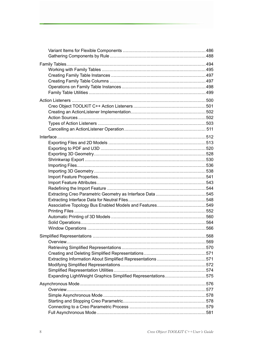
Variant Items for Flexible Components
Gathering Components by Rule
Gathering Components by Model Name
Gathering Components by Size
Gathering Components by Simplified Representation
Gathering Components by Parameters
Gathering Components by Zone
Gathering Components by Distance from a Point
Listing Components By Rule
Family Tables
Working with Family Tables
Accessing Instances
Accessing Columns
Accessing Cell Information
Creating Family Table Instances
Creating Family Table Columns
Operations on Family Table Instances
Family Table Utilities
Action Listeners
Creo Object TOOLKIT C++ Action Listeners
Creating an ActionListener Implementation
Action Sources
Types of Action Listeners
Dimension Level Action Listeners
Session Level Action Listeners
UI Command Action Listeners
Model Level Action listeners
Solid Level Action Listeners
Feature Level Action Listeners
Cancelling an ActionListener Operation
Interface
Exporting Files and 2D Models
Export Instructions
Export Instructions Table
Exporting Drawing Sheets
Exporting to Faceted Formats
Exporting Using Coordinate System
Exporting to PDF and U3D
Exporting 3D Geometry
Export Instructions
Export Utilities
Shrinkwrap Export
Setting Shrinkwrap Options
Surface Subset Options
Faceted Solid Options
Faceted Part Options
VRML Export Options
STL Export Options
Merged Solid Options
Importing Files
Import Instructions
Importing 2D Models
Importing 3D Geometry
Modifying the Imported Layers
Import Feature Properties
Import Feature Attributes
Redefining the Import Feature
Extracting Creo Parametric Geometry as Interface Data
Extracting Interface Data for Neutral Files
Associative Topology Bus Enabled Models and Features
Printing Files
Printer Options
Placement Options
Model Options
Plotter Configuration File (PCF) Options
Automatic Printing of 3D Models
Solid Operations
Window Operations
Creating Import Features from Files
Simplified Representations
Overview
Retrieving Simplified Representations
Creating and Deleting Simplified Representations
Extracting Information About Simplified Representations
Modifying Simplified Representations
Adding Items to and Deleting Items from a Simplified Representation
How to Add Items
How to Remove Items
Simplified Representation Utilities
Expanding LightWeight Graphics Simplified Representations
Asynchronous Mode
Overview
Setting up an Asynchronous Creo Object TOOLKIT Application
Simple Asynchronous Mode
Starting and Stopping Creo Parametric
Setting Up a Noninteractive Session
Connecting to a Creo Parametric Process
Connecting Via Connection ID
Status of a Creo Parametric Process
Getting the Session Object
Full Asynchronous Mode
Troubleshooting Asynchronous Creo Object TOOLKIT
General Problems
Task Based Application Libraries
Managing Application Arguments
Modifying Arguments
Launching a Creo Parametric TOOLKIT DLL
Launching Tasks from Creo Object TOOLKIT C++ Task Libraries
Graphics
Overview
Getting Mouse Input
Drawing a Mouse Box
Cosmetic Properties
Surface Properties
Item Properties
Setting Light Sources
Example 1: Adding a Light Source
Graphics Colors
Setting Colors to Match Existing Entities
Version of Creo Parametric Color Map
Creo Parametric Color Schemes
Line Styles for Graphics
Displaying Graphics
Controlling Graphics Display
Displaying Text in the Graphics Window
Controlling Text Attributes
Controlling Text Fonts
Display Lists and Graphics
Exceptions
External Data
External Data
Introduction to External Data
Compatibility with Creo Parametric TOOLKIT
Accessing External Data
Storing External Data
Initializing Data Objects
Retrieving External Data
Selecting the Node from the External Application Tree
Exceptions
Windchill Connectivity APIs
Introduction
Accessing a PTC Windchill Server from a Creo Session
Accessing Information Before Registering a Server
Registering and Activating a Server
Accessing Information From a Registered Server
Information on Servers in Session
Accessing Workspaces
Creating and Modifying the Workspace
Workflow to Register a Server
To Register a Server with an Existing Workspace
To Register a Server with a New Workspace
Aliased URL
Server Operations
Save
Upload
CheckIn
Retrieval
Checkout and Download
Undo Checkout
Import and Export
File Copy
Server Object Status
Delete Objects
Conflicts During Server Operations
Utility APIs
Technical Summary of Changes
Technical Summary of Changes for Creo 4.0 F000
Critical Technical Changes
Accessing Member Information in a Pattern of Pattern
Non-Applet Based Version of the APIWizard
Applet Based Version of the APIWizard
New Libraries
Alternate Libraries
Change in Behavior of pfcServer::IsObjectCheckedOut
Change in Behavior of pfcTable::CheckIfIsFromFormat
Change in Directory Structure for Creo Installation
Change in Integer Values for Enumerated Data Type pfcComponentType
Digital Rights Management Retired
Disable Notification Messages in Trail Files
Documentation Updated for pfcServer::IsObjectModified
Layout Model Type
List of Classes and Methods
Migrating Creo Parametric TOOLKIT Applications to Object TOOLKIT C++
New Framework User Interface Foundation Classes (UIFC)
New Field to Specify Ribbon File in Registry File
No Special Support for Multithreading in Creo Object TOOLKIT C++ Applications
No Support for Boundary Box Type of Simplified Representation
No Support for wfcLWG_SIMPREP_LEVEL_SELECTED
Retrieving Solids in a Creo Session Linked to Windchill
Standard Libraries
Support for Advanced Licensing
Support for Constraint Creation Methods
Support for Deleting Items While Visiting Them
Support for Feature Subclasses
Support for Creo Unite
wmain() Function
New Functions
Action listeners
Annotations
Application Information: Compatibility
Assemblies
Combined States
Cross Sections
Curve and Surface Collection
Detail Items
Dimensions
Display Style States in a Solid
Drawings
Exploded States
Export Options
External Objects
Family Tables
Features
File Handling
Graphics
Geometry Objects
Import Feature
Interface Data
Layers
License Data
Light Sources
Line Styles for Graphics
Macros
Models
ModelItems
Notes
Parameters
Part Properties
Point
Ray
Relations
Selection
Server Objects
Simplified Representation
Solids
Surface
Tessellation
Tolerances
Units
Visit Methods
Windows
Zone Feature
Superseded Functions
Action listeners
Dimensions
Drawings
Relations
Tessellation
Multithreading
Support for Windchill ProductPoint
Miscellaneous Technical Changes
Configuration Flag to Include Annotations During Export of Creo Models
Display Style for Views
Importing Solid Edge Part and Sheet Metal Part as Features
Importing Solid Edge Sheet Metal Part to Creo Parametric
Support for Neutral File Interface Data in wfcWSolid::ImportAsFeat
Updates to pfcModelItemType Retrieving Material in Models
Technical Summary of Changes for Creo 4.0 M010
Critical Technical Changes
Support for Visual Studio
Technical Summary of Changes for Creo 4.0 M030
Critical Technical Changes
Support for Visual Studio
New Functions
Feature Element Tree
Macros
Layer Operations
Registry File Data
Technical Summary of Changes for Creo 4.0 M040
New Functions
Simplified Representations
Miscellaneous Technical Changes
Plotting a Layout Without BorderSize
Technical Summary of Changes for Creo 4.0 M050
New Functions
View Owner
Technical Summary of Changes for Creo 4.0 M060
New Functions
Assembly
Feature Element Tree
Selection
Technical Summary of Changes for Creo 4.0 M070
New Functions
Drawings
Technical Summary of Changes for Creo 4.0 M080
New Functions
Timer
Technical Summary of Changes for Creo 4.0 M100
Miscellaneous Technical Changes
Support for Automatic Representation
Technical Summary of Changes for Creo 4.0 M110
New Functions
Drawings
Technical Summary of Changes for Creo 4.0 M140
New Functions
Assembly
Combined States
Interface
Technical Summary of Changes for Creo 5.0.0.0
New Functions
Data Exchange
Geometric Tolerances
Feature Element Tree
Layer Operations
Simplified Representation
View Owner
Superseded Functions
Data Exchange
Detail Text
Technical Summary of Changes for Creo 5.0.1.0
Miscellaneous Technical Changes
Support for Import and Export of 3D Manufacturing Format (3MF)
Technical Summary of Changes for Creo 5.0.2.0
New Functions
Drawings
Technical Summary of Changes for Creo 5.0.3.0
New Functions
Timer
Technical Summary of Changes for Creo 5.0.4.0
New Functions
Surface Tessellation
Miscellaneous Technical Changes
Support for Inventor Component
Technical Summary of Changes for Creo 5.0.5.0
New Functions
Embedded Browser
Technical Summary of Changes for Creo 6.0.0.0
Critical Technical Changes
Digitally Signing the Application
New Functions
Action Listeners
Technical Summary of Changes for Creo 6.0.1.0
New Functions
Embedded Browser
Technical Summary of Changes for Creo 6.0.3.0
New Functions
Drawings
Miscellaneous Technical Changes
Support for Automatic Representation
Technical Summary of Changes for Creo 6.0.5.0
New Functions
Interface
Technical Summary of Changes for Creo 7.0.0.0
Critical Technical Changes
Digitally Signing the Application
New Functions
Cross Sections
Drawings
Materials
Solid Bodies
Superseded Functions
Cross Section
Miscellaneous Technical Changes
Support for Automatic Representation
Support for Fluid as Material Type
Change in behavior of the property pfcFeature::GetFeatType
Technical Summary of Changes for Creo 7.0.1.0
New Functions
Assembly
Technical Summary of Changes for Creo 7.0.2.0
New Functions
Annotations
Combined States
Feature Import
Interface
Solids
Creo Object TOOLKIT C++ Registry File
Creo Object TOOLKIT C++ Library Types
Advanced Licensing Options
Sample Applications
Geometry Traversal
Geometry Representations
Index


 2023年江西萍乡中考道德与法治真题及答案.doc
 2012年重庆南川中考生物真题及答案.doc
 2013年江西师范大学地理学综合及文艺理论基础考研真题.doc
 2020年四川甘孜小升初语文真题及答案I卷.doc
 2020年注册岩土工程师专业基础考试真题及答案.doc
 2023-2024学年福建省厦门市九年级上学期数学月考试题及答案.doc
 2021-2022学年辽宁省沈阳市大东区九年级上学期语文期末试题及答案.doc
 2022-2023学年北京东城区初三第一学期物理期末试卷及答案.doc
 2018上半年江西教师资格初中地理学科知识与教学能力真题及答案.doc
 2012年河北国家公务员申论考试真题及答案-省级.doc
 2020-2021学年江苏省扬州市江都区邵樊片九年级上学期数学第一次质量检测试题及答案.doc
 2022下半年黑龙江教师资格证中学综合素质真题及答案.doc