________________________________________________________________________
PROPOSED
SMPTE STANDARD
Video Payload Identification for Digital
________________________________________________________________________
for Television (Dynamic)—
Interfaces
SMPTE 352M
Revision of SMPTE 352M-2001
1 SCOPE
This standard defines the specification of a 4-byte payload identifier which may be added to digital
interfaces for the purpose of identifying the video payload. The payload identifier is intended for application
to existing and future digital interfaces.
The standard defines how the payload identifier is placed into an Ancillary data packet according to the
SMPTE standard 291M. It specifies the sample position, line number(s) and repetition rate of the Ancillary
data packet for different digital interfaces.
The standard also includes definitions for the interpretation of each byte of the 4-byte payload identifier
although the values for many video payloads may have custom definitions. Payload identifier values for
existing video payloads are defined and these establish guidelines for the assignment of appropriate payload
identifier values to future video payloads.
This standard is a dynamic document which allows individually defined parts of this document to be
extended according to the procedures laid down by SMPTE 359M. This document does not allow revisions
to this document which are not backwards compatible with the original document or any prior
extension.Note: SMPTE 352M was first trial published in the July, 2001 issue of SMPTE Journal and
although it did not reach final approval, it has been implemented and equipment is now in use. In order to
distinguish this version from this newly defined dynamic document version, Bit 7 of byte 1 has been set to 1
(see clauses 5.1 and 5.2, and Annex A and B). The first trial publication version should not be used for new
implementations.
2 REFERENCES (DYNAMIC)
The following standards contain provisions which, through reference in this text, constitute provisions of this
standard. At the time of publications, the editions indicated were valid. All standards are subject to revision
and parties to agreements based on this standard are encouraged to investigate the possibility of applying the
most recent edition of the standards indicated below.
This clause is dynamic to allow new standards to be added only as a result of the addition of new video
payload standards or a new digital interface standards to this document in accordance with the Type 1
procedures defined in SMPTE 359M. The addition of such new reference standards must retain backwards
compatibility with earlier versions of this document.
2.1 Normative References
• SMPTE 259M-1997 for Television: 10-Bit 4:2:2 Component and 4fsc Composite Digital Signals -
Serial Digital Interface.
• ITU BT.1358: Studio Parameters of 625 and 525 Line Progressive Scan Television Systems.
• ITU BT.1362: Interfaces for Digital Component Video Signal in 525 and 625 Line Progressive Scan
Page 1 of 23 pages THIS PROPOSAL IS PUBLISHED FOR COMMENT ONLY
Copyright 2002 by THE SOCIETY OF
MOTION PICTURE AND TELEVISION ENGINEERS
595 West Hartsdale Avenue, White Plains, NY 10607
+1 914 761 1100
�
SMPTE 352M
Television Systems.
• SMPTE 344M-2000 for Television: 540 Mb/s Serial Digital Interface.
• SMPTE 347M-2001 for Television: Source Image Mapping for the 540 Mb/s Serial Digital Interface.
• SMPTE 292M-1998 for Television: Bit-Serial Interface for High-Definition Television Systems.
• SMPTE 296M-1997 for Television: 1280*720 Scanning, Analog and Digital Representation and
Analog Interface.
• SMPTE 274M-1995 for Television: 1920*1080 Scanning and Analog and Parallel Digital Interfaces
for Multiple Picture Rates.
• SMPTE RP211-2000 for Television: 1920*1080 Production Format – Implementation of 24P, 25P
and 30P Segmented Frames.
• SMPTE 349M for Television: Transport of Alternate Source Image Formats Through SMPTE 292M.
• SMPTE xxxM (N26.027): Dual-Link 292M Interfaces for 1920 x 1080 Picture Raster
• SMPTE 291M-1998 for Television: Ancillary Data Packet and Space Formatting.
• SMPTE 359M-2001 for Television and Motion Pictures: Dynamic Documents.
2.2 Informative References
• ITU BT.601-5: Studio Encoding Parameters of Digital Television for Standard 4:3 and Wide-Screen
16:9 Aspect Ratios.
• SMPTE 293M-1996 for Television: 720 x 483 Active Line at 59.94-Hz Progressive Scan Production
– Digital Representation.
• SMPTE 294M-1997 for Television: 720 x 483 Active Line at 59.94-Hz Progressive Scan Production
– Bit Serial Interfaces.
• SMPTE 299M-1997 for Television: 24-Bit Digital Audio Format for HDTV Bit-Serial Interface.
• SMPTE 336M-2000 for Television: Data Encoding Protocol using Key-Length-Value.
3 GLOSSARY OF TERMS
• Video Payload: the picture carried by a digital interface and comprising a matrix of horizontal and
vertical pixels. The matrix usually comprises a multiplex of luminance and colour components.
• Interface Transport: the data structure defined by an interface for the purpose of synchronising the
transport words at the receiver. This comprises primarily of the EAV and SAV words. The transport
data is usually expressed as a word of 10 bits although the physical interface is usually serialised.
• Scanning: this is the action of reading the data structure of the interface in a pre-determined order
for transmission. It also refers to the mapping of the picture raster to the interface for transmission.
The scanning of the picture raster and the interface transport are often closely related, the notable
exceptions being the PsF scanning (progressive picture on an interlaced interface) and 3:2 pull-down
scanning (used to map a 24/1.001Hz picture scan onto a 30/1.001Hz interlaced interface).
• Picture Raster: the matrix of samples that represents a digital video picture.
• Sampling: refers to the horizontal arrangement of picture samples, notably the arrangement of
multiplexing the various luminance, chrominance and other signal and data samples.
• Link: in some cases, the picture raster exceeds the capacity available at the digital interface. In these
cases, two or more digital interfaces can be used to provide the total capacity required where each
digital interface is a single link of the combined interface set.
• Channel: in some cases, a digital interface offers sufficient capacity to be able to carry more than
one video payload. In this case, each video payload becomes a channel of the digital interface.
• Picture Rate: the rate at which the pictures were intended to be presented. The picture rate value is
the display rate and may differ with the source picture rate and the interface rate. A hypothetical
example is a motion picture having a source rate of 24Hz, whose intended display rate is 25Hz (for
625-line transmission) that is transported over a 540Mbps SDI transport at twice speed by mapping
each picture frame onto a transport field operating at 50Hz. In this case, the intended picture rate
value is 25Hz. It would not be set to the value of the source picture rate or the value of the transport
rate.
Page 2 of 23 pages
�
SMPTE 352M
4 INTRODUCTION
The video payload identifier may be applied equally to both the parallel and serial forms of digital interface
transports. For convenience, this standard generally refers to the serial (SDI) form. Where this standard
refers only to a SDI transport, it shall be assumed to apply equally to both the serial and the associated
parallel transports.
This standard will first explain the structure of the proposed 4-byte video payload identifier. It will then
define how the video payload identifier is placed in an Ancillary data packet according to SMPTE 291M.
The last clause will define the position and timing of the Ancillary data packet for various interfaces.
Normative annex A will define the video payload identifier values for the following video payload and
digital interface combinations:
• 483/576 line interlaced video payloads on a 270Mbps or 360Mbps digital interface.
• 483/576 line extended video payloads on a 360Mbs single-link digital interface or a 270Mbps dual-
link digital interface.
• 483/576 line video payloads on a 540Mbps digital interface.
• 720 line video payloads on a 1.485Gbps (nominal) digital interface.
• 1080 line video payloads on a 1.485Gbps (nominal) digital interface.
• 483/576 line video payloads on a 1.485Gbps (nominal) digital interface.
• 1080 line video payloads on a 1.485Gbps (nominal) dual-link digital interface.
Normative annex A is a dynamic annex which means that new video payloads and interface combinations
not mentioned above can be added according to the type 1 procedures defined in SMPTE 359M.
Normative Annex B is a historical record of the video payloads and interface combinations as defined by the
first version that was trial published in the July 2001 edition of the SMPTE Journal. This annex is provided
to allow new decoders to recognise payload identifiers encoded according to the first trial publication version
and should not be used by new encoding equipment.
Informative Annex C shows the mapping of the video payload identifier from the Ancillary packet data
structure of SMPTE 291M to the K-L-V data structure of SMPTE 336M as a fixed-length data pack.
Informative Annex D identifies why a video payload identifier is now needed for the identification of a video
payload on a digital interface transport and explains why the video payload identifier is 4 bytes in length.
5 THE VIDEO PAYLOAD IDENTIFIER
The video payload identifier shall be used to identify the video payload carried on a digital interface
transport.
The video payload identifier shall be 4-bytes long where each byte has a separate significance. The first byte
of the video payload identifier shall have the highest significance and subsequent bytes shall be used to
define lower order video payload information. A precise definition of each video payload identifier shall be
provided for each interface based on the following guidelines.
5.1 Common Video Payload Identifier Format
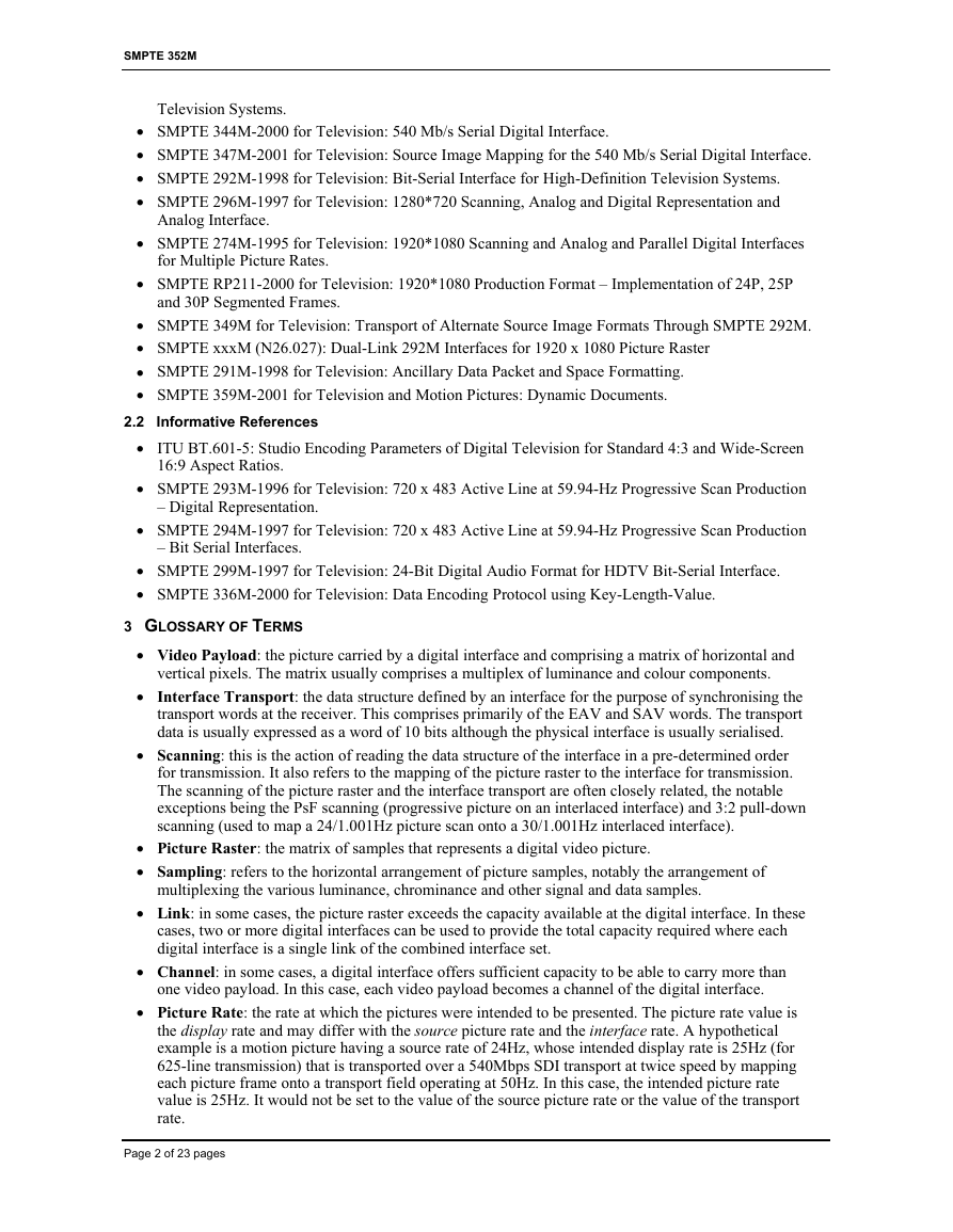
The descriptions of each byte may be summarised as follows in table 1:
Bits
Bit 7
Bit 6
Bit 5
Bit 4
Byte 1
Byte 2
Byte 3
Byte 4
Version Identifier
Video Payload and
Digital Interface
Application specific
(Line or Picture
Standards
related information)
Application specific
(Sampling or aspect
ratio related
information)
Application specific
(Channel
assignment,
Dynamic range, Bit
depth related or
Page 3 of 23 pages
�
SMPTE 352M
Bit 3
Bit 2
Bit 1
Bit 0
(mandatory)
other information)
Picture rate
Sampling Structure
identification
Table 1a: Generalized Video Payload Identifier Byte Definitions for Digital Transports
Byte 2
Interlaced (0) or
Progressive (1)
Transport
Interlaced (0) or
Progressive (1)
Picture
Reserved
Reserved
Byte 3
Image aspect ratio
4:3 (0) or 16:9 (1)
Reserved
Reserved
Reserved
Picture rate
Sampling Structure
identification
Bits
Bit 7
Bit 6
Bit 5
Bit 4
Bit 3
Bit 2
Bit 1
Bit 0
Byte 4
Channel assignment
Single link or ch1 of
multi-link (0h),
ch2 of multi-link (1h),
ch3 of multi-link (2h),
ch4 of multi-link (3h)
Reserved
Dynamic range
100%(0h),200%(1h)
or 400%(2h)
Reserved (3h)
Reserved
Bit depth
8 bit (0h), 10bit (1h)
or 12bit (2h),
Reserved (3h)
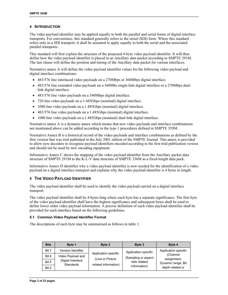
Table 1b (Dynamic): Default Video Payload Identifier Field Definitions
Byte 1 provides a mandatory definition of the video payload and digital interface standard. The remaining 3
bytes, as defined in tables 1a and 1b, provide default definitions for individual fields, although these may
vary on a case by case basis depending on the value given in Byte 1.
The default meaning of the reserved bits of table 1b may be assigned in a future revision of this document in
accordance with Type 1 procedures defined in SMPTE 359M. Such assignment must retain backwards
compatibility with earlier versions of this document.
5.2 Byte 1: Video Payload and Digital Interface Identification
This first byte has the highest significance and shall be used to identify the combination of video payload
format and digital interface transport.
Note that some digital interfaces can carry a number of different video payload formats at the same transport
bit rate by changing the timing and repetition rates of the timing reference signals embedded in the digital
interface synchronization words. Furthermore, video payload formats can now be mapped onto several
digital interface transports. Thus the first byte identifies the combination of both the video payload format
and its associated digital interface.
The first byte of the video payload identifier shall have a non-zero value for all valid video payloads. Thus
the first byte can be used to address up to 127 video payload and digital interface standards.
Bit 7 of byte 1 shall be used to define the payload identification version:
‘1’ identifies version 1 based on this document. (see Annex A)
‘0’ identifies version 0 based on SMPTE 352M as trial published in the July, 2001 issue of the
SMPTE Journal.(see Annex B)
Page 4 of 23 pages
�
SMPTE 352M
5.3 Byte 2: Picture Rate and Scanning Method
The second byte can be used to identify the picture rate and the picture and transport scanning methods as
shown in table 1b.
By default, bit b7 is used to identify whether the digital interface uses a progressive or interlaced transport
structure. The default value of b7 is ‘0’ which identifies an interlaced transport.
Informative Note: bit b7 is provided for rapid and reliable detection of the transport scanning structure. The
digital interface scanning structure can be found through the detection of the ‘F’ bit which has a static ‘0’
value for progressive transports, and toggles between ‘0’ (first field) and ‘1’ (second field) for interlaced
transports. This detection may take several transport frames to ensure accuracy whereas this single bit, b7,
can provide the information on a per-frame basis.
By default, bit b6 is used to identify whether the picture has been scanned as progressive or interlaced. The
default value of b6 is ‘0’ which identifies an interlaced scanned picture.
Informative note: PsF video payloads are identified by a progressive scanning of the video payload
transported over an interlaced digital interface transport carrying the progressive video payload as a first and
second picture segment within the transport frame duration. These first and second picture segments are
indicated by the first and second field indicators in the digital interface transport.
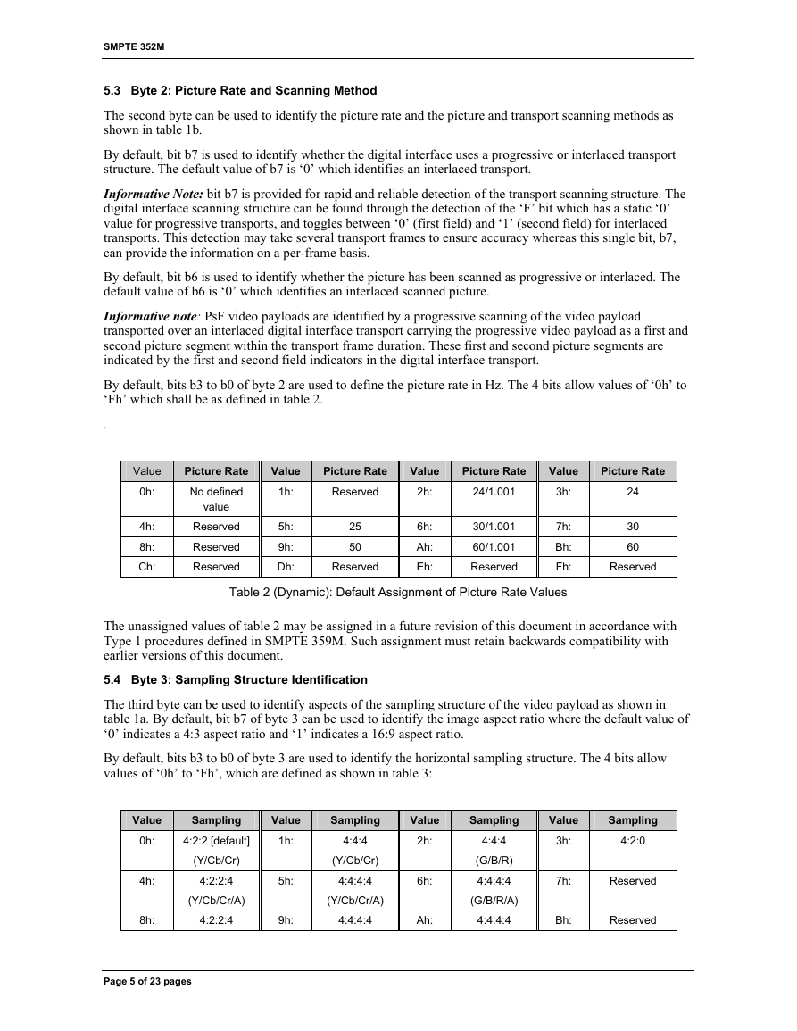
By default, bits b3 to b0 of byte 2 are used to define the picture rate in Hz. The 4 bits allow values of ‘0h’ to
‘Fh’ which shall be as defined in table 2.
.
Value
0h:
4h:
8h:
Ch:
Picture Rate
No defined
value
Reserved
Reserved
Reserved
Value
1h:
Picture Rate
Reserved
Value
2h:
Picture Rate
24/1.001
Value
3h:
5h:
9h:
Dh:
25
50
Reserved
6h:
Ah:
Eh:
30/1.001
60/1.001
Reserved
7h:
Bh:
Fh:
Picture Rate
24
30
60
Reserved
Table 2 (Dynamic): Default Assignment of Picture Rate Values
The unassigned values of table 2 may be assigned in a future revision of this document in accordance with
Type 1 procedures defined in SMPTE 359M. Such assignment must retain backwards compatibility with
earlier versions of this document.
5.4 Byte 3: Sampling Structure Identification
The third byte can be used to identify aspects of the sampling structure of the video payload as shown in
table 1a. By default, bit b7 of byte 3 can be used to identify the image aspect ratio where the default value of
‘0’ indicates a 4:3 aspect ratio and ‘1’ indicates a 16:9 aspect ratio.
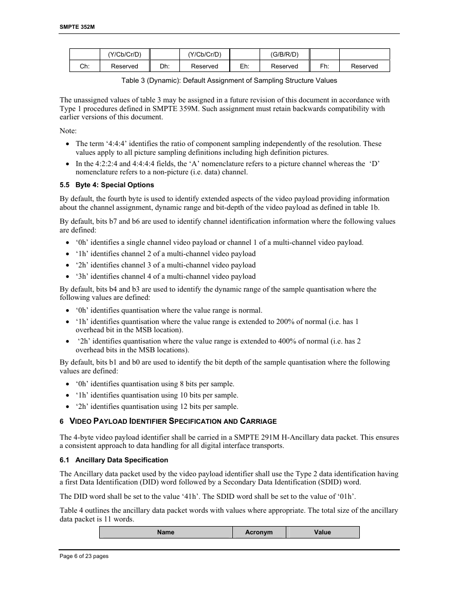
By default, bits b3 to b0 of byte 3 are used to identify the horizontal sampling structure. The 4 bits allow
values of ‘0h’ to ‘Fh’, which are defined as shown in table 3:
Value
0h:
Sampling
4:2:2 [default]
Value
1h:
(Y/Cb/Cr)
4:2:2:4
(Y/Cb/Cr/A)
4:2:2:4
4h:
8h:
5h:
9h:
Sampling
4:4:4
(Y/Cb/Cr)
4:4:4:4
(Y/Cb/Cr/A)
4:4:4:4
Value
2h:
6h:
Ah:
Sampling
4:4:4
(G/B/R)
4:4:4:4
(G/B/R/A)
4:4:4:4
Value
3h:
Sampling
4:2:0
7h:
Reserved
Bh:
Reserved
Page 5 of 23 pages
�
SMPTE 352M
(Y/Cb/Cr/D)
Reserved
(Y/Cb/Cr/D)
Reserved
Dh:
Ch:
Eh:
(G/B/R/D)
Reserved
Fh:
Reserved
Table 3 (Dynamic): Default Assignment of Sampling Structure Values
The unassigned values of table 3 may be assigned in a future revision of this document in accordance with
Type 1 procedures defined in SMPTE 359M. Such assignment must retain backwards compatibility with
earlier versions of this document.
Note:
• The term ‘4:4:4’ identifies the ratio of component sampling independently of the resolution. These
values apply to all picture sampling definitions including high definition pictures.
• In the 4:2:2:4 and 4:4:4:4 fields, the ‘A’ nomenclature refers to a picture channel whereas the ‘D’
nomenclature refers to a non-picture (i.e. data) channel.
5.5 Byte 4: Special Options
By default, the fourth byte is used to identify extended aspects of the video payload providing information
about the channel assignment, dynamic range and bit-depth of the video payload as defined in table 1b.
By default, bits b7 and b6 are used to identify channel identification information where the following values
are defined:
• ‘0h’ identifies a single channel video payload or channel 1 of a multi-channel video payload.
• ‘1h’ identifies channel 2 of a multi-channel video payload
• ‘2h’ identifies channel 3 of a multi-channel video payload
• ‘3h’ identifies channel 4 of a multi-channel video payload
By default, bits b4 and b3 are used to identify the dynamic range of the sample quantisation where the
following values are defined:
• ‘0h’ identifies quantisation where the value range is normal.
• ‘1h’ identifies quantisation where the value range is extended to 200% of normal (i.e. has 1
overhead bit in the MSB location).
‘2h’ identifies quantisation where the value range is extended to 400% of normal (i.e. has 2
overhead bits in the MSB locations).
•
By default, bits b1 and b0 are used to identify the bit depth of the sample quantisation where the following
values are defined:
• ‘0h’ identifies quantisation using 8 bits per sample.
• ‘1h’ identifies quantisation using 10 bits per sample.
• ‘2h’ identifies quantisation using 12 bits per sample.
6 VIDEO PAYLOAD IDENTIFIER SPECIFICATION AND CARRIAGE
The 4-byte video payload identifier shall be carried in a SMPTE 291M H-Ancillary data packet. This ensures
a consistent approach to data handling for all digital interface transports.
6.1 Ancillary Data Specification
The Ancillary data packet used by the video payload identifier shall use the Type 2 data identification having
a first Data Identification (DID) word followed by a Secondary Data Identification (SDID) word.
The DID word shall be set to the value ‘41h’. The SDID word shall be set to the value of ‘01h’.
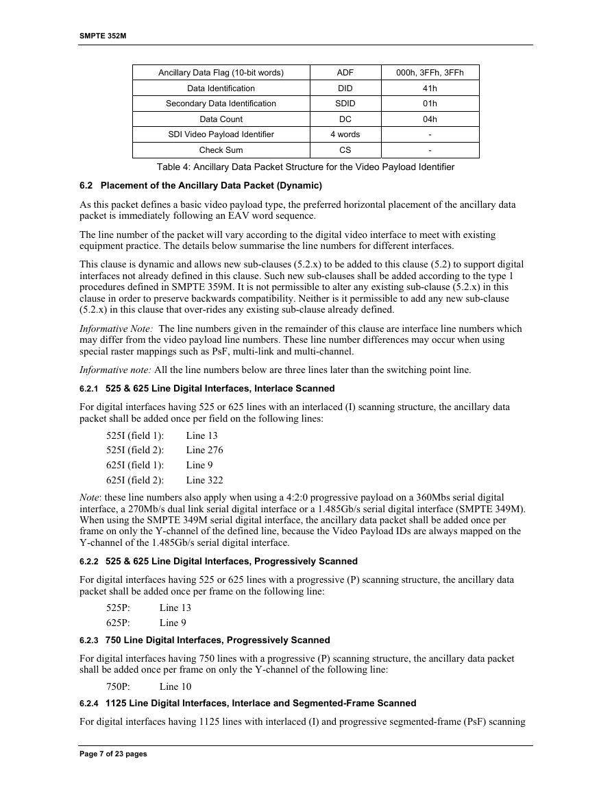
Table 4 outlines the ancillary data packet words with values where appropriate. The total size of the ancillary
data packet is 11 words.
Name
Acronym
Value
Page 6 of 23 pages
�
SMPTE 352M
Ancillary Data Flag (10-bit words)
Data Identification
Secondary Data Identification
Data Count
SDI Video Payload Identifier
Check Sum
ADF
DID
SDID
DC
4 words
CS
000h, 3FFh, 3FFh
41h
01h
04h
-
-
Table 4: Ancillary Data Packet Structure for the Video Payload Identifier
6.2 Placement of the Ancillary Data Packet (Dynamic)
As this packet defines a basic video payload type, the preferred horizontal placement of the ancillary data
packet is immediately following an EAV word sequence.
The line number of the packet will vary according to the digital video interface to meet with existing
equipment practice. The details below summarise the line numbers for different interfaces.
This clause is dynamic and allows new sub-clauses (5.2.x) to be added to this clause (5.2) to support digital
interfaces not already defined in this clause. Such new sub-clauses shall be added according to the type 1
procedures defined in SMPTE 359M. It is not permissible to alter any existing sub-clause (5.2.x) in this
clause in order to preserve backwards compatibility. Neither is it permissible to add any new sub-clause
(5.2.x) in this clause that over-rides any existing sub-clause already defined.
Informative Note: The line numbers given in the remainder of this clause are interface line numbers which
may differ from the video payload line numbers. These line number differences may occur when using
special raster mappings such as PsF, multi-link and multi-channel.
Informative note: All the line numbers below are three lines later than the switching point line.
6.2.1 525 & 625 Line Digital Interfaces, Interlace Scanned
For digital interfaces having 525 or 625 lines with an interlaced (I) scanning structure, the ancillary data
packet shall be added once per field on the following lines:
525I (field 1):
525I (field 2):
625I (field 1):
625I (field 2):
Line 13
Line 276
Line 9
Line 322
Note: these line numbers also apply when using a 4:2:0 progressive payload on a 360Mbs serial digital
interface, a 270Mb/s dual link serial digital interface or a 1.485Gb/s serial digital interface (SMPTE 349M).
When using the SMPTE 349M serial digital interface, the ancillary data packet shall be added once per
frame on only the Y-channel of the defined line, because the Video Payload IDs are always mapped on the
Y-channel of the 1.485Gb/s serial digital interface.
6.2.2 525 & 625 Line Digital Interfaces, Progressively Scanned
For digital interfaces having 525 or 625 lines with a progressive (P) scanning structure, the ancillary data
packet shall be added once per frame on the following line:
525P:
625P:
Line 13
Line 9
6.2.3 750 Line Digital Interfaces, Progressively Scanned
For digital interfaces having 750 lines with a progressive (P) scanning structure, the ancillary data packet
shall be added once per frame on only the Y-channel of the following line:
750P:
Line 10
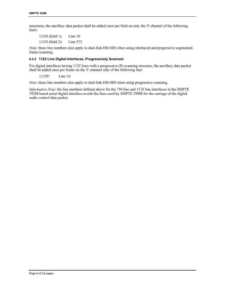
6.2.4 1125 Line Digital Interfaces, Interlace and Segmented-Frame Scanned
For digital interfaces having 1125 lines with interlaced (I) and progressive segmented-frame (PsF) scanning
Page 7 of 23 pages
�
SMPTE 352M
structures, the ancillary data packet shall be added once per field on only the Y-channel of the following
lines:
1125I (field 1):
1125I (field 2):
Line 10
Line 572
Note: these line numbers also apply to dual-link HD-SDI when using interlaced and progressive segmented-
frame scanning.
6.2.5 1125 Line Digital Interfaces, Progressively Scanned
For digital interfaces having 1125 lines with a progressive (P) scanning structure, the ancillary data packet
shall be added once per frame on the Y-channel only of the following line:
1125P:
Line 10
Note: these line numbers also apply to dual-link HD-SDI when using progressive scanning.
Informative Note: the line numbers defined above for the 750 line and 1125 line interfaces in the SMPTE
292M based serial digital interface avoids the lines used by SMPTE 299M for the carriage of the digital
audio control data packet.
Page 8 of 23 pages
�


 2023年江西萍乡中考道德与法治真题及答案.doc
 2012年重庆南川中考生物真题及答案.doc
 2013年江西师范大学地理学综合及文艺理论基础考研真题.doc
 2020年四川甘孜小升初语文真题及答案I卷.doc
 2020年注册岩土工程师专业基础考试真题及答案.doc
 2023-2024学年福建省厦门市九年级上学期数学月考试题及答案.doc
 2021-2022学年辽宁省沈阳市大东区九年级上学期语文期末试题及答案.doc
 2022-2023学年北京东城区初三第一学期物理期末试卷及答案.doc
 2018上半年江西教师资格初中地理学科知识与教学能力真题及答案.doc
 2012年河北国家公务员申论考试真题及答案-省级.doc
 2020-2021学年江苏省扬州市江都区邵樊片九年级上学期数学第一次质量检测试题及答案.doc
 2022下半年黑龙江教师资格证中学综合素质真题及答案.doc