Sensors and Actuators A 247 (2016) 522–538
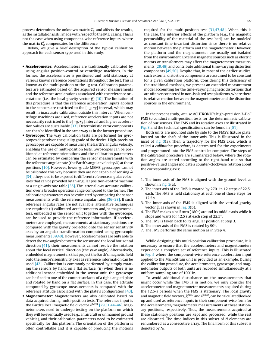
Contents lists available at ScienceDirect
Sensors
and
Actuators
A:
Physical
j o u r n a l h o m e p a g e : w w w . e l s e v i e r . c o m / l o c a t e / s n a
Improvements in deterministic error modeling and calibration
of inertial sensors and magnetometers
Gorkem Secer, Billur Barshan∗
Department of Electrical and Electronics Engineering, Bilkent University, Bilkent, TR-06800 Ankara, Turkey
a
r
t
i
c
l
e
i
n
f
o
a
b
s
t
r
a
c
t
We consider the deterministic modeling, calibration, and model parameter estimation of two commonly
employed inertial measurement units based on real test data acquired from a flight motion simulator.
Each unit comprises three tri-axial devices: an accelerometer, a gyroscope, and a magnetometer. We
perform the deterministic error modeling and calibration of accelerometers based on an improved mea-
surement model, and the technique we propose for gyroscopes lowers costs by eliminating the need
for additional sensors and relaxing the test bed requirement. We present an extended measurement
model for magnetometers that reduces calibration errors by modeling orientation-dependent hard-iron
errors in a gimbaled angular position-control machine. While we employ the model-based Levenberg-
Marquardt optimization algorithm for the parameter estimation of accelerometers and magnetometers,
we use a model-free evolutionary optimization algorithm (particle swarm optimization) for estimating
the calibration parameters of gyroscopes. Errors are considerably reduced as a result of proper modeling
and calibration.
© 2016 Elsevier B.V. All rights reserved.
Article history:
Received 29 January 2016
Received in revised form 14 June 2016
Accepted 20 June 2016
Available online 1 July 2016
Keywords:
Inertial sensors
Accelerometer
Gyroscope
Magnetometer
Deterministic error modeling
Measurement model
In-field calibration
Model parameter estimation
Ellipsoid parameter estimation
Levenberg-Marquardt algorithm
Particle swarm optimization
1. Introduction
Inertial sensors were mainly only used in aeronautics and
maritime applications until the nineties because of the high
cost associated with
the high-accuracy requirements. With
developments in micro-electro-mechanical systems (MEMS), the
availability of small, lower-cost, medium-performance inertial sen-
sors has opened up new possibilities for their use, such as the
recognition of daily activities [1], physical therapy and home-based
rehabilitation [2], biomechanics [3], detecting and classifying falls
[4,5], shock and vibration analysis, navigation of unmanned vehi-
cles [6–8], and state estimation and dynamic modeling of legged
robots [9].
Inertial measurement units (IMUs) typically contain gyroscopes
and accelerometers, sometimes used in conjunction with mag-
netometers. Each device can be sensitive around a single axis or
multiple axes (usually two or three). An accelerometer detects spe-
cific force, which is proportionate to the acceleration of the sensor
∗ Corresponding author.
E-mail addresses: gorkem.secer@ceng.metu.edu.tr (G. Secer),
billur@ee.bilkent.edu.tr (B. Barshan).
http://dx.doi.org/10.1016/j.sna.2016.06.024
0924-4247/© 2016 Elsevier B.V. All rights reserved.
relative to an inertial reference frame along its axis of sensitivity.
A gyroscope senses the angular rate about an axis of sensitivity
with respect to an inertial reference frame [10,11]. Magnetometers
measure the magnetic field strength at a given location superposed
with the Earth’s magnetic field [12]. They are used in a wide range of
disciplines, from archaeology [13] to vehicle navigation and control
[14].
Consumer-grade inertial sensors have attracted much interest
recently because of their decreasing cost due to developments in
MEMS technology [15]. Measurements by inertial sensors often
deviate from the ground truth since the devices suffer from various
error types, which can be constant or time varying. The rate output
of accelerometers and gyroscopes needs to be integrated twice or
once to obtain the linear or angular position, respectively. Because
of the integration process, even very small errors at the output accu-
mulate very rapidly and the position error becomes considerably
large in a few seconds and starts drifting in time (i.e., proportionate
with the time cube for the linear and the time square for the angu-
lar position) [16]. This effect is exacerbated for low-grade sensors.
Consumer-grade inertial sensors can be used for longer periods of
time on their own if modeled and calibrated properly, but may need
to be corrected from time to time by an external aid that provides
an absolute reference for the ground truth [17,18]. Thus, to improve
�
G. Secer, B. Barshan / Sensors and Actuators A 247 (2016) 522–538
523
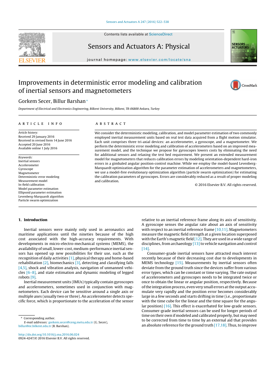
Fig. 1. The two sensor units used in this study: (a) MicroStrain 3DM-GX2 [22] and (b) Xsens MTx [23].
the accuracy of linear and angular position estimates, it is necessary
to characterize and model the errors at the sensor output precisely.
The same holds for magnetometers that suffer from various error
types.
Most previous works have divided the calibration problem into
two distinct parts (deterministic and stochastic modeling) because
of their different mathematical natures [10,19,20]. Here, we follow
the same approach and focus on deterministic calibration only.
Stochastic calibration is considered in a different study [21].
Working from their raw outputs, we consider the deterministic
calibration of two widely used consumer-grade IMUs and compare
their performances: MicroStrain’s 3DM-GX2 [22] and Xsens’ MTx
[23], depicted in Fig. 1, with their technical specifications provided
in the respective references. The units are small, light, and com-
prised of three tri-axial devices: an accelerometer, a gyroscope, and
a magnetometer. The main objective of this study is to effectively
model and estimate the units’ deterministic calibration parame-
ters so that both their stand-alone and aided performances can be
improved.
Motivated by insights gained from earlier work, we propose
improved models and algorithmic ideas and implement them to
improve the sensor calibration process. The main contributions of
this article are threefold:
• We propose an improvement to the traditional measurement
model used in 1g tests for modeling the deterministic errors
of accelerometers. The method’s effectiveness is shown through
experiments, and the results are compared with those of the tra-
ditional model.
• We employ a low-cost calibration technique to estimate the error
components associated with gyroscopes. Our technique is based
on comparing the attitude of the IMU, calculated by integrating
the gyroscope measurements, with the reference attitude pro-
vided by a 3-DoF flight motion simulator (FMS). In this way, we
eliminate the need for any additional sensors to perform the cal-
ibration, unlike previously used low-cost gyroscope calibration
techniques. Another novel aspect of this work is that to esti-
mate the model parameters that minimize the attitude error
of gyroscopes, we use a global optimization algorithm [particle
swarm optimization (PSO)] instead of gradient-based techniques,
to avoid convergence to local minima.
• We propose an extended sensor measurement model for mag-
netometers that reduces calibration errors by modeling the
orientation-dependent magnetic disturbances in gimbaled angu-
lar position-control machines. We experimentally verify that
incorporating in the model the relative motion between the
magnetometer and the magnetic distortion sources in the envi-
ronment enhances the calibration accuracy.
The rest of this article is organized as follows: In Section 2, we
first develop individual deterministic sensor measurement models
for each type of sensor and then propose a unified measurement
model for all three sensor types. Section 3 describes the data acqui-
sition experiments conducted for calibrating the sensors and briefly
reviews geometric and algebraic parameter estimation techniques.
We then present our model parameter estimation results based on
the acquired data and propose an extended measurement model
for magnetometers. We compare the two units in terms of mea-
surement quality based on the results of deterministic calibration.
In Section 4, we summarize our contributions, make concluding
remarks, and provide some directions for future research. In the
appendices, we provide background information on the two opti-
mization algorithms that we use for parameter estimation.
2. Sensor measurement models
The general measurement model of the sensors evaluated in this
(1)
R3 ×
Rdim(�) →
R3. The em, e, and n ∈
study is given by:
em = h(e, �)
+ n
where h(e, �) :
R3 denote the
measured sensor output, the true value of the excitation signal, and
the additive stochastic measurement noise vector, respectively. The
calibration parameter vector � involved in this model needs to be
estimated accurately in the scope of deterministic calibration.
The following notation is used throughout: The measured sensor
output em can be one of am, ωm, or Bm, for the accelerometer, gyro-
scope, and magnetometer, respectively. The true excitation signal
e can be one of a, ω, or B, which represent the true values of the
specific acceleration, angular rate, and magnetic field strength vec-
tors. A vector u expressed with respect to a coordinate frame f is
denoted by u f , and the rotational transformation matrix C f 2
, trans-
u f 1 . Orthonormal
forms a vector u f 1 from frame f1 to f2 as u f 2 =
unit vectors of the x, y, and z axes of a given frame f are respectively
denoted by i f ,j f , and k f .
f 1
C f 2
f 1
To develop the deterministic measurement model of the sen-
sors, we first need to introduce several coordinate frames:
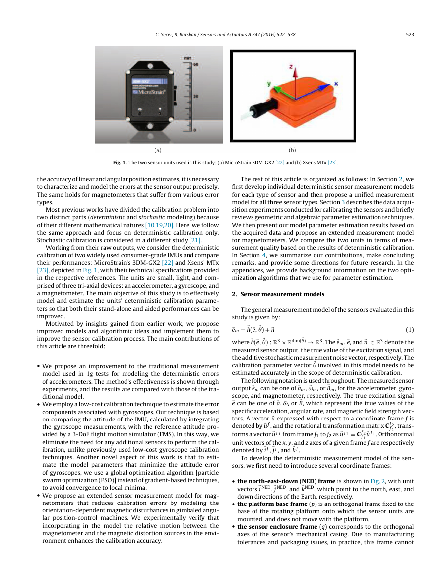
• the north-east-down (NED) frame is shown in Fig. 2, with unit
vectors i NED,j NED, and kNED, which point to the north, east, and
down directions of the Earth, respectively.
• the platform base frame (p) is an orthogonal frame fixed to the
base of the rotating platform onto which the sensor units are
mounted, and does not move with the platform.
• the sensor enclosure frame (q) corresponds to the orthogonal
axes of the sensor’s mechanical casing. Due to manufacturing
tolerances and packaging issues, in practice, this frame cannot
�
524
G. Secer, B. Barshan / Sensors and Actuators A 247 (2016) 522–538
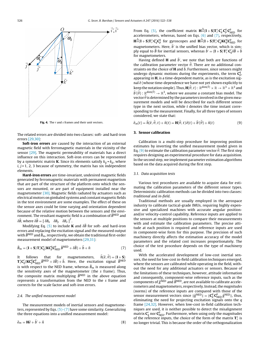
illustrated in Fig. 4. This kinematic relation between frames r and s
can be modeled by the non-orthogonalization (cross-axis sensitivity)
matrix:
0
cos(˛1)
0
0
(3)
⎡
⎣ 1
sin(˛1)
=
T s
r
⎤
⎦
cos(˛3)
sin(˛2) sin(˛3)
cos(˛2) sin(˛3)
∈
{1, 2, 3}
T s
r
where ˛i, i
are the sensor-to-sensor axis misalignment
angles (Fig. 4). With this definition, a vector ur can be transformed
from frame r to s as us =
ur.
=
[ Sx
According to a first-order approximation at the sensor output
[19], we introduce a diagonal scale factor error matrix S such that
diag(S)
Sz ]. A factor of (I + S) multiplies the true excita-
×
tion signal in the measurement model, where I is the 3
3 identity
matrix, so that the output of each sensor axis is scaled by a different
amount in general.
Sy
Fig. 2. The NED frame and the Earth’s frame of reference.
Adopted from [67].
be perfectly aligned with the sensor’s actual sensitivity axes (s
frame). This frame moves with the platform onto which the sen-
sor units are attached.
• the orthogonal sensor sensitivity frame (r) is the idealized,
orthogonal sensor sensitivity frame.
• the non-orthogonal sensor sensitivity frame (s) represents the
set of the sensor’s actual sensitivity axes. Deviation from orthog-
onality stems from manufacturing tolerances in general, and may
affect navigation performance significantly.
When the input to the sensor is zero, the deviation of the
output from the zero level is the bias error [6,19], denoted by
b
=
[ bx by bz ]T in this study. The bias error may change with
the sensor’s operating temperature and may drift in time. Since the
experiments are conducted over short periods of time in this study,
we assume a constant bias level.
The deterministic error components and the transformation
matrices introduced above are common to both inertial sensors
and magnetometers.
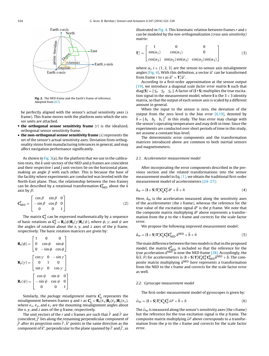
As shown in Fig. 3(a), for the platform that we use in the calibra-
tion tests, the k unit vectors of the NED and p frames are coincident
and their respectivei and j unit vectors lie on the horizontal plane,
making an angle ˇ with each other. This is because the base of
the facility where experiments are conducted was leveled with the
North-East plane. Thus, the relationship between the two frames
can be described by a rotational transformation Cp
axis by ˇ:
NED about the k
⎡
⎣ cos ˇ
− sin ˇ
0
=
Cp
NED
⎤
⎦
sin ˇ 0
cos ˇ 0
1
0
(2)
The matrix Cq
p can be expressed mathematically by a sequence
of basic rotations as Cq
Rx()Ry()Rz( ), where , , and are
the angles of rotation about the x, y, and z axes of the p frame,
respectively. The basic rotation matrices are given by:
p =
cos
−
sin
0
0
0
⎡
⎣ 1
⎡
⎣ cos 0
⎡
⎣ cos
1
sin 0
0
=
Rx()
=
Ry()
=
Rz( )
0
sin
cos
−
sin
0
cos
⎤
⎦
⎤
⎦
⎤
⎦
sin 0
−
sin cos 0
0
1
0
Similarly, the package misalignment matrix Cr
q represents the
=
misalignment between frames q and r as Cr
Rx(x)Ry(y)Rz(z),
q
where x, y, and z are the mounting misalignment angles about
the x, y, and z axes of the q frame, respectively.
The unit vectors of the r and s frames are such that ir and is are
coincident,jr lies along the remaining perpendicular component of
js after its projection onto ir, kr points in the same direction as the
component of ks, perpendicular to the plane spanned byir andjr, as
2.1. Accelerometer measurement model
rCr
qCq
p
+
S) T s
ap + b + n
After incorporating the error components described in the pre-
vious section and the related transformations into the sensor
measurement model in Eq. (1), we obtain the traditional first-order
measurement model of accelerometers [24–27]:
am =
(I
(4)
Here, am is the acceleration measured along the sensitivity axes
of the accelerometer (the s frame), whereas the reference for the
true value of the excitation signal ap is the p frame. We note that
the composite matrix multiplying ap above represents a transfor-
mation from the p to the s frame and corrects for the scale factor
error.
We propose the following improved measurement model:
am =
(I
+
S) T s
rCr
qCq
pCp
NED
aNED + b + n
(5)
The main difference between the two models is that in the proposed
model, the matrix Cp
NED is included so that the reference for the
true acceleration aNED is now the NED frame [28]. Accordingly, the
h(e, �) for accelerometers is (I
aNED + b. The com-
posite matrix multiplying aNED here represents a transformation
from the NED to the s frame and corrects for the scale factor error
as well.
+
S) T s
p Cp
qCq
rCr
NED
2.2. Gyroscope measurement model
The first-order measurement model of gyroscopes is given by:
rCr
qCq
p
ωp + b + n
+
S) T s
ωm =
(I
(6)
The ωm is measured along the sensor’s sensitivity axes (the s frame)
but the reference for the true excitation signal is the p frame. The
composite matrix multiplying ωp above corresponds to a transfor-
mation from the p to the s frame and corrects for the scale factor
error.
�
G. Secer, B. Barshan / Sensors and Actuators A 247 (2016) 522–538
525
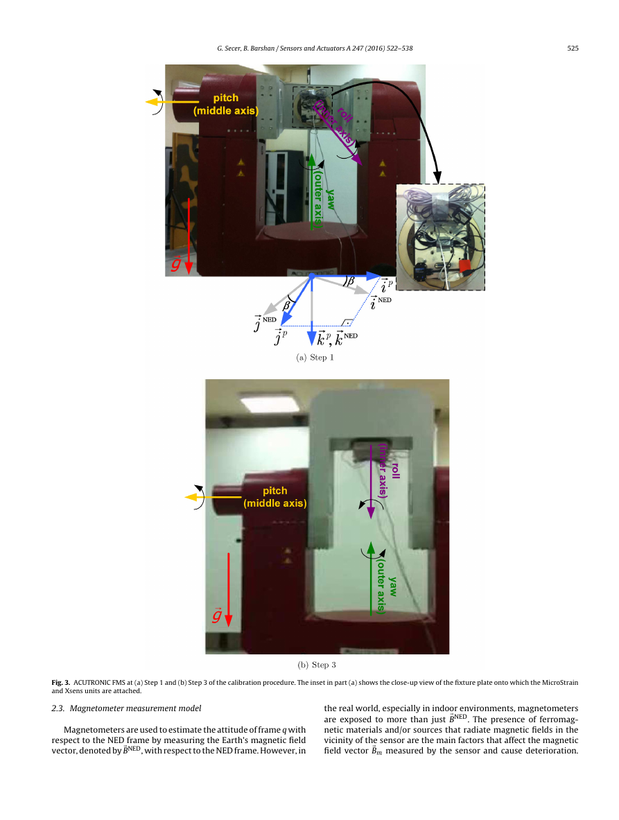
Fig. 3. ACUTRONIC FMS at (a) Step 1 and (b) Step 3 of the calibration procedure. The inset in part (a) shows the close-up view of the fixture plate onto which the MicroStrain
and Xsens units are attached.
2.3. Magnetometer measurement model
Magnetometers are used to estimate the attitude of frame q with
respect to the NED frame by measuring the Earth’s magnetic field
vector, denoted by BNED, with respect to the NED frame. However, in
the real world, especially in indoor environments, magnetometers
are exposed to more than just BNED. The presence of ferromag-
netic materials and/or sources that radiate magnetic fields in the
vicinity of the sensor are the main factors that affect the magnetic
field vector Bm measured by the sensor and cause deterioration.
�
526
G. Secer, B. Barshan / Sensors and Actuators A 247 (2016) 522–538
(I
=
r Cr
r Cr
qCq
pCp
q Cq
p Cp
qKCq
+
S)T s
+
S)T s
r Cr
+
S) T s
Having defined H and b
From Eq. (5), the coefficient matrix H�=(I
NED for
accelerometers, whereas, based on Eqs. (6) and (7), respectively,
+
H�=(I
p for gyroscopes and H�=(I
S)T s
NED for
magnetometers. Here, b
is the unified bias vector, which is sim-
ply equal to B for inertial sensors, whereas b
qıB + b
r Cr
for magnetometers.
, we note that both are functions of
the calibration parameter vector �. There are no additional con-
straints on the choice of H and b. Furthermore, since sensors might
undergo dynamic motions during the experiments, the term Cq
p,
appearing in H, is a time-dependent matrix, as is the excitation sig-
nal e (whose time-dependence we have not yet shown explicitly to
keep the notation simple). Thus, H(�, t) :
R3 and
(�) :
b
R3, where we assume a constant bias model. The
vector � is determined by the parameters involved in the given mea-
surement models and will be described for each different sensor
type in the next section, while t denotes the time instant corre-
sponding to the measurement. Finally, for all three types of sensors
considered, we state that:
H(�, t) e(t)
em(t)
=
= h(e, �, t)
Rdim(�) →
Rdim(�) ×
+ n(t)
+ n(t)
+ b
R3 ×
(�)
→
(9)
R
3. Sensor calibration
Calibration is a multi-step procedure for improving position
estimates by inverting the unified measurement model given in
Eq. (9) to estimate the calibration parameter vector �. The first step
requires designing an experimental procedure for data acquisition.
In the second step, we implement parameter estimation algorithms
based on the data acquired during the first step.
3.1. Data acquisition tests
Various test procedures are available to acquire data for esti-
mating the calibration parameters of the different sensor types.
Deterministic calibration methods can be divided into two classes:
traditional and in-field.
Traditional methods are usually employed in the aerospace
industry to calibrate tactical-grade IMUs, requiring highly expen-
sive and specialized machines with accurate angular position-
and/or velocity-control capability. Reference inputs are applied to
the sensors at multiple positions to compare their measurements
with and estimate the calibration parameters. The precise atti-
tude at each position is required and reference inputs are used
in component-wise form for this purpose. The precision of such
machinery directly affects the estimation accuracy of the model
parameters and the related cost increases proportionately. The
choice of the test procedure depends on the type of machinery
used.
With the accelerated development of low-cost inertial sen-
sors, the need for low-cost in-field calibration techniques emerged,
where the sensors are calibrated while operating in the field, with-
out the need for any additional actuators or sensors. Because of
the limitations of these techniques, however, attitude information
and consequently, component-wise reference inputs, such as the
components of gNED and BNED, are not available to calibrate accele-
rometers and magnetometers, respectively. Instead, the magnitudes
(norms) of the reference inputs are compared with those of the
gNED, thus,
sensor measurement vectors since
eliminating the need for projecting excitation signals onto the q
frame [24,32]. However, when low-cost in-field calibration tech-
niques are used, it is neither possible to detect the misalignment
matrix Cr
NED. Furthermore, when using only the magnitudes
of the reference inputs, the choice of the form of the matrix T s
r is
no longer trivial. This is because the order of the orthogonalization
gNED
q nor Cp
Cq
p Cp
NED
=
Fig. 4. The r and s frames and their unit vectors.
The related errors are divided into two classes: soft- and hard-iron
errors [29,30]:
Soft-iron errors are caused by the interaction of an external
magnetic field with ferromagnetic materials in the vicinity of the
sensor [29]. The magnetic permeability of materials has a direct
influence on this interaction. Soft-iron errors can be represented
by a symmetric matrix K. Since its elements satisfy kij = kji, where
i, j = 1, 2, 3 because of symmetry, the matrix has six independent
elements.
ıBy
[ ıBx
ıBz ]T .
Hard-iron errors are time-invariant, undesired magnetic fields
generated by ferromagnetic materials with permanent magnetism
that are part of the structure of the platform onto which the sen-
sors are mounted, or are part of equipment installed near the
magnetometer [30]. Magnetic fields radiated by actuators such as
electrical motors on gimbaled systems and constant magnetic fields
in the test environment are some examples. The effect of these on
the sensor axes could be time varying and orientation dependent
because of the relative motion between the sensors and the envi-
ronment. The resultant magnetic field is a combination of BNED and
ıB, where ıB =
Modifying Eq. (5) to include K and ıB for soft- and hard-iron
errors and replacing the excitation signal and the measured output
with BNED and Bm, respectively, we obtain the traditional first-order
measurement model of magnetometers [29,31]:
Bm =
(I
(7)
+
S)
It
for magnetometers,
+ b. Here, the excitation signal BNED
T s
rCr
is with respect to the NED frame, whereas Bm is measured along
the sensitivity axes of the magnetometer (the s frame). Thus,
the composite matrix multiplying BNED in the above equation
represents a transformation from the NED to the s frame and
corrects for the scale factor and soft-iron errors.
follows
pCp
q(KCq
that
BNED +
+ b + n
BNED +
h(e, �)
+
S) T s
q(KCq
ıB)
ıB)
=
(I
pCp
rCr
NED
NED
2.4. The unified measurement model
The measurement models of inertial sensors and magnetome-
ters, represented by Eqs. (5)–(7) have some similarity. Generalizing
the three equations into a unified measurement model:
em =
+ n
+ b
He
(8)
�
G. Secer, B. Barshan / Sensors and Actuators A 247 (2016) 522–538
527
process determines the unknown matrix Cr
q, and affects the results,
as the installation is still made with respect to the IMU casing. This is
not the case when using component-wise reference inputs, where
the matrix Cr
q compensates for the difference.
Below, we give a brief description of the typical calibration
approach for each sensor type used in this study:
• Accelerometer: Accelerometers are traditionally calibrated by
using angular position-control or centrifuge machines. In the
former, the accelerometer is positioned and held stationary at
various known reference orientations throughout the test. This is
known as the multi-position or the 1g test. Calibration parame-
ters are estimated based on the acquired sensor measurements
and the reference accelerations associated with the reference ori-
entations (i.e., the local gravity vector g) [10]. The limitation of
this procedure is that the reference acceleration inputs applied
to the sensors are restricted to the [−g, +g] interval, which may
result in inaccurate calibration outside this interval. When cen-
trifuge machines are used, reference acceleration inputs are not
necessarily restricted to the [−g, +g] interval and higher accelera-
tion values are sustainable [33]. Deterministic error components
can then be identified in the same way as in the former procedure.
• Gyroscope: The way calibration tests are performed for gyro-
scopes depends on the quality grade of the device. High-precision
gyroscopes are capable of measuring the Earth’s angular velocity,
enabling the use of multi-position tests. Gyroscopes can be pos-
itioned at reference orientations and the calibration parameters
can be estimated by comparing the sensor measurements with
the reference angular rate (the Earth’s angular velocity ω) at these
positions [10]. However, lower-grade MEMS gyroscopes cannot
be calibrated this way because they are not capable of sensing ω
[34]; they need to be exposed to different reference angular veloc-
ities that can be provided by an angular position-control machine
or a single-axis rate table [35]. The latter allows accurate calibra-
tion over a broader operation range compared to the former. The
calibration parameters can be estimated by comparing the sensor
measurements with the reference angular rates [36–38]. If such
reference angular rates are not available, alternative techniques
are required: (i) calibrated accelerometers and/or magnetome-
ters, embedded in the sensor unit together with the gyroscope,
can be used to provide the reference information. If accelero-
meters are employed, measurements at stationary positions are
compared with the gravity projected onto the sensor sensitivity
axes by an angular transformation computed using gyroscopic
measurements [39,40]. However, accelerometers are only able to
detect the two angles between the sensor and the local horizontal
direction [41]; their measurements cannot resolve the rotation
about the local vertical direction (the yaw angle). Alternatively,
embedded magnetometers that project the Earth’s magnetic field
onto the sensor’s sensitivity axes as reference information can be
used [42]. Calibration is commonly performed by simply rotat-
ing the sensors by hand on a flat surface. (ii) when there is no
additional sensor embedded in the sensor unit, the gyroscope
can be fixed to one of the contact surfaces of a right-angled plate
and rotated by hand on a flat surface. In this case, the attitude
computed by gyroscope measurements is compared with the
reference attitude associated with the plate’s configuration [43].
• Magnetometer: Magnetometers are also calibrated based on
data acquired during multi-position tests. The reference input is
the Earth’s local magnetic field vector BNED [29,31,44–46]. Mag-
netometers need to undergo testing on the platform on which
they will be eventually used (e.g., an aircraft or unmanned ground
vehicle), and their calibration parameters need to be estimated
specifically for this platform. The orientation of the platform is
often controllable and it is capable of producing the motions
required for the multi-position test [31,47,48]. When this is
the case, the interior effects of the platform (e.g., the magnetic
permeability of the material of the test bed) can be modeled
as constant time-invariant distortion since there is no relative
motion between the platform and the magnetometer. However,
the platform and the magnetometer are usually not isolated
from the environment. External magnetic sources such as electric
motors or transformers may affect the magnetometer measure-
ments [29,46] and contribute additional time-varying distortion
components [49,50]. Despite that, in most of the earlier studies,
such external distortion components are assumed to be constant
for a given calibration platform. Considering this deficiency of
the traditional methods, we present an extended measurement
model accounting for the time-varying magnetic distortions that
are often encountered in non-isolated test platforms, where there
is relative motion between the magnetometer and the distortion
sources in the environment.
In the present study, we use ACUTRONIC’s high-precision 3-DoF
FMS to conduct multi-position tests for the deterministic calibra-
tion of our sensors. The FMS and its rotation axes are illustrated in
Fig. 3 and the technical specifications can be found in [51].
Both units are mounted side by side to the FMS’s fixture plate,
located on the shaft of the inner axis. This is illustrated in the
inset of Fig. 3(a). Then, a trajectory for the FMS axes, which is
called a calibration procedure, is determined for the experiments
and programmed into the FMS controller computer. The steps of
the calibration procedure are summarized below, where the rota-
tion angles are stated according to the right-hand rule so that
positive-valued angles indicate a counter-clockwise rotation about
the corresponding axis:
shown in Fig. 3(a).
1. The inner axis of the FMS is aligned with the ground level, as
2. The inner axis of the FMS is rotated by 270◦ in 12 steps of 22.5◦
each. The FMS is held stationary at each one of those steps for
12.5 s.
vector g, as shown in Fig. 3(b).
stops and waits for 12.5 s at each step of 22.5◦.
3. The inner axis of the FMS is aligned with the vertical gravity
4. The FMS makes a half turn (180◦) around its middle axis while it
5. The FMS is taken back to its angular position at Step 3.
6. The inner axis of the FMS is rotated by 90◦.
7. The FMS performs the same motion as in Step 4.
While designing this multi-position calibration procedure, it is
necessary to ensure that the accelerometers and magnetometers
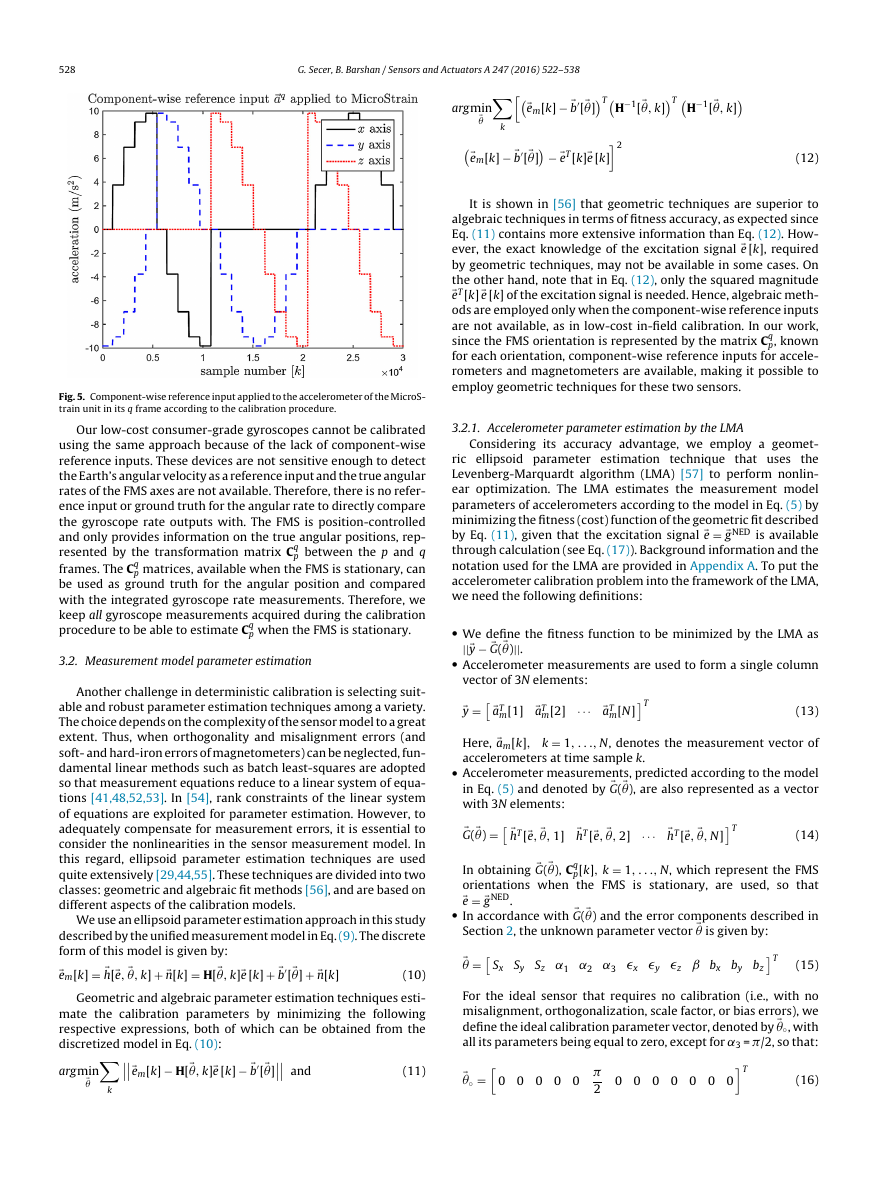
experience a complete set of reference inputs. This is illustrated
in Fig. 5 where the component-wise reference acceleration input
applied to the MicroStrain unit is provided as an example. During
the calibration procedure, the accelerometer, gyroscope, and mag-
netometer outputs of both units are recorded simultaneously at a
uniform sampling rate of 100 Hz.
To avoid additional disturbance on the measurements that
might occur while the FMS is in motion, we only consider the
accelerometer and magnetometer measurements acquired during
the 12.5-s periods when the FMS is stationary. The local gravity
and magnetic field vectors, gNED and BNED, can be calculated/looked
up and used as reference inputs in their component-wise form for
the accelerometer/magnetometer measurements at these station-
ary positions, respectively. Thus, the measurements acquired at
these stationary positions are kept and processed, while the rest
are discarded. The time indices in this subset of N elements are
renumbered as a consecutive array. The final form of this subset is
denoted by Ns.
�
528
G. Secer, B. Barshan / Sensors and Actuators A 247 (2016) 522–538
em[k]
k
em[k]
[�]
T
[�]
2
− eT [k]e [k]
− b
H
− b
argmin�
T
−1[�, k]
−1[�, k]
H
(12)
It is shown in [56] that geometric techniques are superior to
algebraic techniques in terms of fitness accuracy, as expected since
Eq. (11) contains more extensive information than Eq. (12). How-
ever, the exact knowledge of the excitation signal e [k], required
by geometric techniques, may not be available in some cases. On
the other hand, note that in Eq. (12), only the squared magnitude
eT [k] e [k] of the excitation signal is needed. Hence, algebraic meth-
ods are employed only when the component-wise reference inputs
are not available, as in low-cost in-field calibration. In our work,
since the FMS orientation is represented by the matrix Cq
p, known
for each orientation, component-wise reference inputs for accele-
rometers and magnetometers are available, making it possible to
employ geometric techniques for these two sensors.
3.2.1. Accelerometer parameter estimation by the LMA
technique
that uses
Considering its accuracy advantage, we employ a geomet-
ric ellipsoid parameter estimation
the
Levenberg-Marquardt algorithm (LMA) [57] to perform nonlin-
ear optimization. The LMA estimates the measurement model
parameters of accelerometers according to the model in Eq. (5) by
minimizing the fitness (cost) function of the geometric fit described
by Eq. (11), given that the excitation signal e = gNED is available
through calculation (see Eq. (17)). Background information and the
notation used for the LMA are provided in Appendix A. To put the
accelerometer calibration problem into the framework of the LMA,
we need the following definitions:
(13)
m[1]
T
aT
m[N]
aT
− G(�)||.
• We define the fitness function to be minimized by the LMA as
||y
• Accelerometer measurements are used to form a single column
vector of 3N elements:
y =
aT
·
·
·
m[2]
Here, am[k], k
=
1, . . ., N, denotes the measurement vector of
accelerometers at time sample k.
• Accelerometer measurements, predicted according to the model
in Eq. (5) and denoted by G(�), are also represented as a vector
with 3N elements:
G(�)
hT [e, �, 2]
In obtaining G(�), Cq
=
1, . . ., N, which represent the FMS
orientations when the FMS
is stationary, are used, so that
e
= gNED.
• In accordance with G(�) and the error components described in
Section 2, the unknown parameter vector � is given by:
T
� =
Sx Sy Sz ˛1 ˛2 ˛3 x y z ˇ bx by bz
hT [e, �, 1]
hT [e, �, N]
p[k], k
T
(14)
(15)
=
·
·
·
For the ideal sensor that requires no calibration (i.e., with no
misalignment, orthogonalization, scale factor, or bias errors), we
define the ideal calibration parameter vector, denoted by �◦, with
all its parameters being equal to zero, except for ˛3 = /2, so that:
�◦ =
0 0 0 0 0 0 0
0 0 0 0 0
T
(16)
2
Fig. 5. Component-wise reference input applied to the accelerometer of the MicroS-
train unit in its q frame according to the calibration procedure.
Our low-cost consumer-grade gyroscopes cannot be calibrated
using the same approach because of the lack of component-wise
reference inputs. These devices are not sensitive enough to detect
the Earth’s angular velocity as a reference input and the true angular
rates of the FMS axes are not available. Therefore, there is no refer-
ence input or ground truth for the angular rate to directly compare
the gyroscope rate outputs with. The FMS is position-controlled
and only provides information on the true angular positions, rep-
resented by the transformation matrix Cq
p between the p and q
frames. The Cq
p matrices, available when the FMS is stationary, can
be used as ground truth for the angular position and compared
with the integrated gyroscope rate measurements. Therefore, we
keep all gyroscope measurements acquired during the calibration
procedure to be able to estimate Cq
p when the FMS is stationary.
3.2. Measurement model parameter estimation
Another challenge in deterministic calibration is selecting suit-
able and robust parameter estimation techniques among a variety.
The choice depends on the complexity of the sensor model to a great
extent. Thus, when orthogonality and misalignment errors (and
soft- and hard-iron errors of magnetometers) can be neglected, fun-
damental linear methods such as batch least-squares are adopted
so that measurement equations reduce to a linear system of equa-
tions [41,48,52,53]. In [54], rank constraints of the linear system
of equations are exploited for parameter estimation. However, to
adequately compensate for measurement errors, it is essential to
consider the nonlinearities in the sensor measurement model. In
this regard, ellipsoid parameter estimation techniques are used
quite extensively [29,44,55]. These techniques are divided into two
classes: geometric and algebraic fit methods [56], and are based on
different aspects of the calibration models.
We use an ellipsoid parameter estimation approach in this study
described by the unified measurement model in Eq. (9). The discrete
form of this model is given by:
em[k]
H[�, k]e [k]
=
= h[e, �, k]
+ n[k]
+ n[k]
+ b
[�]
(10)
Geometric and algebraic parameter estimation techniques esti-
mate the calibration parameters by minimizing the following
respective expressions, both of which can be obtained from the
discretized model in Eq. (10):
argmin�
em[k]
and
H[�, k]e [k]
−
− b
[�]
(11)
k
�
G. Secer, B. Barshan / Sensors and Actuators A 247 (2016) 522–538
529
Considering the centrifugal acceleration effects caused by the
Earth’s rotation, the value of gNED at the location where the exper-
iments are conducted can be calculated using [10]:
gNED = g
− (R
) ωNED2
+
2
sin 2� 0
+
cos 2�)
(1
(17)
T
where g
=
[0 0 9.80665]T m/s2 is the standard gravity vector and
ωNED, R, , and � represent the Earth’s angular velocity vector with
respect to the NED frame, the radius of the Earth, altitude with
respect to sea level, and the latitude angle that changes between
−90◦ and 90◦, respectively. The calculated gNED vector is given by
gNED =
[−0.0167 0 9.7782]T m/s2.
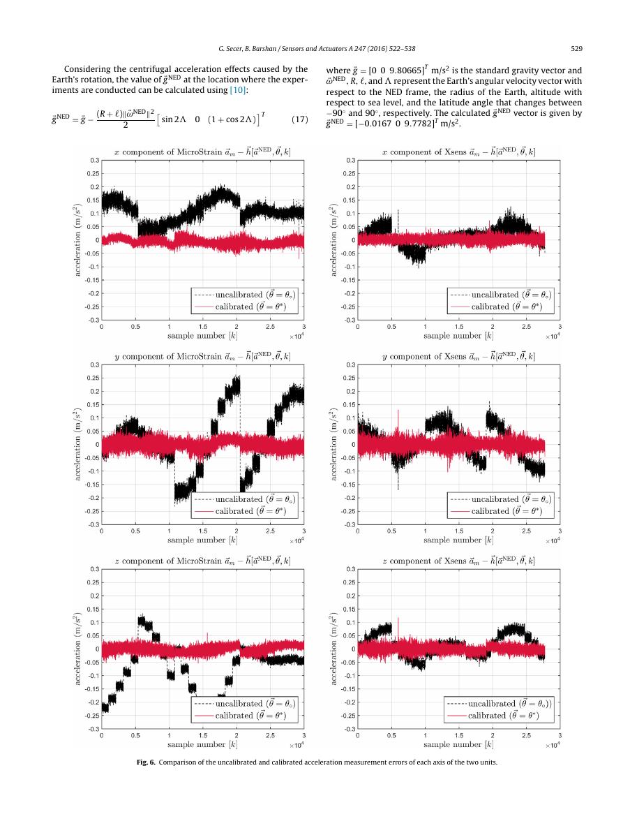
Fig. 6. Comparison of the uncalibrated and calibrated acceleration measurement errors of each axis of the two units.
�


 2023年江西萍乡中考道德与法治真题及答案.doc
 2012年重庆南川中考生物真题及答案.doc
 2013年江西师范大学地理学综合及文艺理论基础考研真题.doc
 2020年四川甘孜小升初语文真题及答案I卷.doc
 2020年注册岩土工程师专业基础考试真题及答案.doc
 2023-2024学年福建省厦门市九年级上学期数学月考试题及答案.doc
 2021-2022学年辽宁省沈阳市大东区九年级上学期语文期末试题及答案.doc
 2022-2023学年北京东城区初三第一学期物理期末试卷及答案.doc
 2018上半年江西教师资格初中地理学科知识与教学能力真题及答案.doc
 2012年河北国家公务员申论考试真题及答案-省级.doc
 2020-2021学年江苏省扬州市江都区邵樊片九年级上学期数学第一次质量检测试题及答案.doc
 2022下半年黑龙江教师资格证中学综合素质真题及答案.doc