logo资料库

OCP NIC 3.0 Design Specification.pdf

第1页 / 共224页
第2页 / 共224页
第3页 / 共224页
第4页 / 共224页
第5页 / 共224页
第6页 / 共224页
第7页 / 共224页
第8页 / 共224页
资料共224页,剩余部分请下载后查看
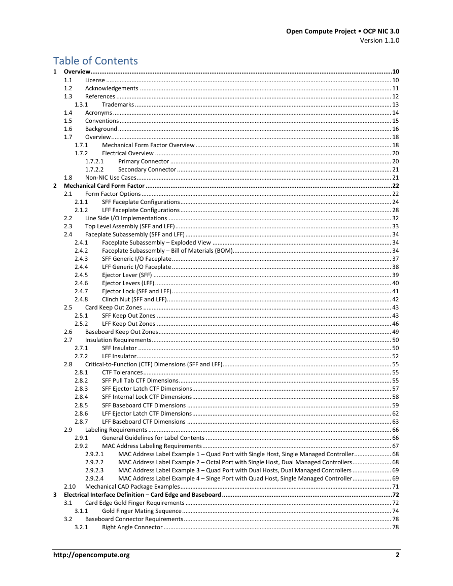
1 Overview
1.1 License
1.2 Acknowledgements
1.3 References
1.3.1 Trademarks
1.4 Acronyms
1.5 Conventions
1.6 Background
1.7 Overview
1.7.1 Mechanical Form Factor Overview
1.7.2 Electrical Overview
1.7.2.1 Primary Connector
1.7.2.2 Secondary Connector
1.8 Non-NIC Use Cases
2 Mechanical Card Form Factor
2.1 Form Factor Options
2.1.1 SFF Faceplate Configurations
2.1.2 LFF Faceplate Configurations
2.2 Line Side I/O Implementations
2.3 Top Level Assembly (SFF and LFF)
2.4 Faceplate Subassembly (SFF and LFF)
2.4.1 Faceplate Subassembly – Exploded View
2.4.2 Faceplate Subassembly – Bill of Materials (BOM)
2.4.3 SFF Generic I/O Faceplate
2.4.4 LFF Generic I/O Faceplate
2.4.5 Ejector Lever (SFF)
2.4.6 Ejector Levers (LFF)
2.4.7 Ejector Lock (SFF and LFF)
2.4.8 Clinch Nut (SFF and LFF)
2.5 Card Keep Out Zones
2.5.1 SFF Keep Out Zones
2.5.2 LFF Keep Out Zones
2.6 Baseboard Keep Out Zones
2.7 Insulation Requirements
2.7.1 SFF Insulator
2.7.2 LFF Insulator
2.8 Critical-to-Function (CTF) Dimensions (SFF and LFF)
2.8.1 CTF Tolerances
2.8.2 SFF Pull Tab CTF Dimensions
2.8.3 SFF Ejector Latch CTF Dimensions
2.8.4 SFF Internal Lock CTF Dimensions
2.8.5 SFF Baseboard CTF Dimensions
2.8.6 LFF Ejector Latch CTF Dimensions
2.8.7 LFF Baseboard CTF Dimensions
2.9 Labeling Requirements
2.9.1 General Guidelines for Label Contents
2.9.2 MAC Address Labeling Requirements
2.9.2.1 MAC Address Label Example 1 – Quad Port with Single Host, Single Managed Controller
2.9.2.2 MAC Address Label Example 2 – Octal Port with Single Host, Dual Managed Controllers
2.9.2.3 MAC Address Label Example 3 – Quad Port with Dual Hosts, Dual Managed Controllers
2.9.2.4 MAC Address Label Example 4 – Singe Port with Quad Host, Single Managed Controller
2.10 Mechanical CAD Package Examples
3 Electrical Interface Definition – Card Edge and Baseboard
3.1 Card Edge Gold Finger Requirements
3.1.1 Gold Finger Mating Sequence
3.2 Baseboard Connector Requirements
3.2.1 Right Angle Connector
3.2.2 Right Angle Offset
3.2.3 Straddle Mount Connector
3.2.4 Straddle Mount Offset and PCB Thickness Options
3.2.5 LFF Connector Locations
3.3 Pin Definition
3.3.1 Primary Connector
3.3.2 Secondary Connector
3.4 Signal Descriptions
3.4.1 PCIe Interface Pins
3.4.2 PCIe Present and Bifurcation Control Pins
3.4.3 SMBus Interface Pins
3.4.4 NC-SI over RBT Interface Pins
3.4.5 Scan Chain Pins
3.4.6 Power Supply Pins
3.4.7 USB 2.0 (A68/A69) – Primary Connector Only
3.4.8 UART (A68/A69) – Secondary Connector Only
3.4.9 RFU[1:4] Pins
3.5 PCIe Bifurcation Mechanism
3.5.1 PCIe OCP NIC 3.0 Card to Baseboard Bifurcation Configuration (PRSNTA#, PRSNTB[3:0]#)
3.5.2 PCIe Baseboard to OCP NIC 3.0 Card Bifurcation Configuration (BIF[2:0]#)
3.5.3 PCIe Bifurcation Decoder
3.5.4 Bifurcation Detection Flow
3.5.5 PCIe Bifurcation Examples
3.5.5.1 Single Host (1 x16) Baseboard with a 1 x16 OCP NIC 3.0 Card (Single Controller)
3.5.5.2 Single Host (2 x8) Baseboard with a 2 x8 OCP NIC 3.0 Card (Dual Controllers)
3.5.5.3 Quad Host (4 x4) Baseboard with a 4 x4 OCP NIC 3.0 Card (Single Controller)
3.5.5.4 Quad Host (4 x4) Baseboard with a 4 x4 OCP NIC 3.0 Card (Quad Controllers)
3.5.5.5 Single Host (1 x16, no Bifurcation) Baseboard with a 2 x8 OCP NIC 3.0 Card (Dual Controller)
3.6 PCIe REFCLK and PERST# Mapping
3.6.1 SFF PCIe REFCLK and PERST# Mapping
3.6.2 LFF PCIe REFCLK and PERST# Mapping
3.6.3 REFCLK and PERST# Mapping Expansion
3.7 Port Numbering and LED Implementations
3.7.1 OCP NIC 3.0 Port Naming and Port Numbering
3.7.2 OCP NIC 3.0 Card LED Configuration
3.7.3 OCP NIC 3.0 Card LED Ordering
3.7.4 Baseboard LEDs Configuration over the Scan Chain
3.8 Power State Machine
3.8.1 NIC Power Off
3.8.2 ID Mode
3.8.3 Aux Power Mode
3.8.4 Main Power Mode
3.8.5 Programming Mode
3.9 Power Supply Rail Requirements and Slot Power Envelopes
3.10 Hot Swap Considerations for +12V_EDGE and +3.3V_EDGE Rails
3.11 Power Sequence Timing Requirements
3.12 Digital I/O Specifications
4 Management and Pre-OS Requirements
4.1 Sideband Management Interface and Transport
4.2 NC-SI Traffic
4.3 Management Controller (MC) MAC Address Provisioning
4.4 ASIC Die Temperature Reporting
4.5 Power Consumption Reporting
4.6 Pluggable Transceiver Module Status and Temperature Reporting
4.7 Management and Pre-OS Firmware Inventory and Update
4.7.1 Secure Firmware
4.7.2 Firmware Inventory
4.7.3 Firmware Inventory and Update in Multi-Host Environments
4.8 NC-SI Package Addressing and Hardware Arbitration Requirements
4.8.1 NC-SI over RBT Package Addressing
4.8.2 Arbitration Ring Connections
4.9 SMBus 2.0 Addressing Requirements
4.9.1 SMBus Address Map
4.10 FRU EEPROM
4.10.1 FRU EEPROM Addressing and Size
4.10.2 FRU EEPROM Write Protection
4.10.3 FRU EEPROM Content Requirements
4.10.4 FRU Template
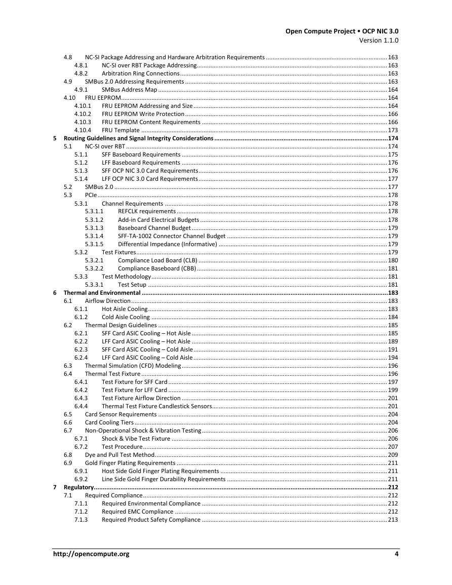
5 Routing Guidelines and Signal Integrity Considerations
5.1 NC-SI over RBT
5.1.1 SFF Baseboard Requirements
5.1.2 LFF Baseboard Requirements
5.1.3 SFF OCP NIC 3.0 Card Requirements
5.1.4 LFF OCP NIC 3.0 Card Requirements
5.2 SMBus 2.0
5.3 PCIe
5.3.1 Channel Requirements
5.3.1.1 REFCLK requirements
5.3.1.2 Add-in Card Electrical Budgets
5.3.1.3 Baseboard Channel Budget
5.3.1.4 SFF-TA-1002 Connector Channel Budget
5.3.1.5 Differential Impedance (Informative)
5.3.2 Test Fixtures
5.3.2.1 Compliance Load Board (CLB)
5.3.2.2 Compliance Baseboard (CBB)
5.3.3 Test Methodology
5.3.3.1 Test Setup
6 Thermal and Environmental
6.1 Airflow Direction
6.1.1 Hot Aisle Cooling
6.1.2 Cold Aisle Cooling
6.2 Thermal Design Guidelines
6.2.1 SFF Card ASIC Cooling – Hot Aisle
6.2.2 LFF Card ASIC Cooling – Hot Aisle
6.2.3 SFF Card ASIC Cooling – Cold Aisle
6.2.4 LFF Card ASIC Cooling – Cold Aisle
6.3 Thermal Simulation (CFD) Modeling
6.4 Thermal Test Fixture
6.4.1 Test Fixture for SFF Card
6.4.2 Test Fixture for LFF Card
6.4.3 Test Fixture Airflow Direction
6.4.4 Thermal Test Fixture Candlestick Sensors
6.5 Card Sensor Requirements
6.6 Card Cooling Tiers
6.7 Non-Operational Shock & Vibration Testing
6.7.1 Shock & Vibe Test Fixture
6.7.2 Test Procedure
6.8 Dye and Pull Test Method
6.9 Gold Finger Plating Requirements
6.9.1 Host Side Gold Finger Plating Requirements
6.9.2 Line Side Gold Finger Durability Requirements
7 Regulatory
7.1 Required Compliance
7.1.1 Required Environmental Compliance
7.1.2 Required EMC Compliance
7.1.3 Required Product Safety Compliance
7.1.4 Required Immunity (ESD) Compliance
7.2 Recommended Compliance
7.2.1 Recommended Environmental Compliance
7.2.2 Recommended EMC Compliance
8 Revision History
8.1 Document Revision History
8.2 FRU Content Revision History
OCP NIC 3.0 Design Specification Version 1.1.0 Author: OCP Server Workgroup, OCP NIC subgroup
Open Compute Project  OCP NIC 3.0 Version 1.1.0 1.3.1 1.7.1 1.7.2 2.1.1 2.1.2 2.2 2.3 2.4 1.8 2.1 1.1 1.2 1.3 1.4 1.5 1.6 1.7 2.4.1 2.4.2 2.4.3 2.4.4 2.4.5 2.4.6 2.4.7 2.4.8 Table of Contents 1 Overview ..........................................................................................................................................................................10 License ......................................................................................................................................................................... 10 Acknowledgements ..................................................................................................................................................... 11 References ................................................................................................................................................................... 12 Trademarks ........................................................................................................................................................ 13 Acronyms ..................................................................................................................................................................... 14 Conventions ................................................................................................................................................................. 15 Background .................................................................................................................................................................. 16 Overview ...................................................................................................................................................................... 18 Mechanical Form Factor Overview .................................................................................................................... 18 Electrical Overview ............................................................................................................................................ 20 Primary Connector ................................................................................................................................... 20 1.7.2.1 Secondary Connector ............................................................................................................................... 21 1.7.2.2 Non-NIC Use Cases ....................................................................................................................................................... 21 2 Mechanical Card Form Factor ...........................................................................................................................................22 Form Factor Options .................................................................................................................................................... 22 SFF Faceplate Configurations ............................................................................................................................. 24 LFF Faceplate Configurations ............................................................................................................................. 28 Line Side I/O Implementations .................................................................................................................................... 32 Top Level Assembly (SFF and LFF) ................................................................................................................................ 33 Faceplate Subassembly (SFF and LFF) .......................................................................................................................... 34 Faceplate Subassembly – Exploded View .......................................................................................................... 34 Faceplate Subassembly – Bill of Materials (BOM).............................................................................................. 34 SFF Generic I/O Faceplate .................................................................................................................................. 37 LFF Generic I/O Faceplate .................................................................................................................................. 38 Ejector Lever (SFF) ............................................................................................................................................. 39 Ejector Levers (LFF) ............................................................................................................................................ 40 Ejector Lock (SFF and LFF) .................................................................................................................................. 41 Clinch Nut (SFF and LFF) ..................................................................................................................................... 42 Card Keep Out Zones ................................................................................................................................................... 43 SFF Keep Out Zones ........................................................................................................................................... 43 LFF Keep Out Zones ........................................................................................................................................... 46 Baseboard Keep Out Zones .......................................................................................................................................... 49 Insulation Requirements .............................................................................................................................................. 50 SFF Insulator ...................................................................................................................................................... 50 LFF Insulator ....................................................................................................................................................... 52 Critical-to-Function (CTF) Dimensions (SFF and LFF) .................................................................................................... 55 CTF Tolerances ................................................................................................................................................... 55 SFF Pull Tab CTF Dimensions .............................................................................................................................. 55 SFF Ejector Latch CTF Dimensions ...................................................................................................................... 57 SFF Internal Lock CTF Dimensions ...................................................................................................................... 58 SFF Baseboard CTF Dimensions ......................................................................................................................... 59 LFF Ejector Latch CTF Dimensions ...................................................................................................................... 62 LFF Baseboard CTF Dimensions ......................................................................................................................... 63 Labeling Requirements ................................................................................................................................................ 66 General Guidelines for Label Contents .............................................................................................................. 66 MAC Address Labeling Requirements ................................................................................................................ 67 MAC Address Label Example 1 – Quad Port with Single Host, Single Managed Controller ...................... 68 MAC Address Label Example 2 – Octal Port with Single Host, Dual Managed Controllers ....................... 68 MAC Address Label Example 3 – Quad Port with Dual Hosts, Dual Managed Controllers ....................... 69 MAC Address Label Example 4 – Singe Port with Quad Host, Single Managed Controller ....................... 69 2.10 Mechanical CAD Package Examples ............................................................................................................................. 71 3 Electrical Interface Definition – Card Edge and Baseboard ................................................................................................72 Card Edge Gold Finger Requirements .......................................................................................................................... 72 Gold Finger Mating Sequence ............................................................................................................................ 74 Baseboard Connector Requirements ........................................................................................................................... 78 Right Angle Connector ....................................................................................................................................... 78 2.8.1 2.8.2 2.8.3 2.8.4 2.8.5 2.8.6 2.8.7 2.9.2.1 2.9.2.2 2.9.2.3 2.9.2.4 3.1.1 3.2.1 2.5 2.6 2.7 2.8 2.5.1 2.5.2 2.7.1 2.7.2 2.9 2.9.1 2.9.2 3.1 3.2 http://opencompute.org 2
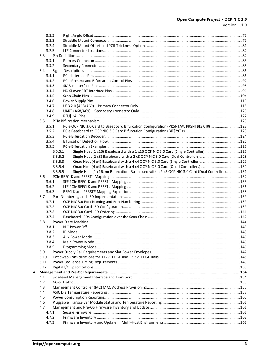
Open Compute Project  OCP NIC 3.0 Version 1.1.0 3.3 3.4 3.5 3.5.1 3.5.2 3.5.3 3.5.4 3.5.5 3.2.2 3.2.3 3.2.4 3.2.5 3.3.1 3.3.2 3.4.1 3.4.2 3.4.3 3.4.4 3.4.5 3.4.6 3.4.7 3.4.8 3.4.9 Right Angle Offset .............................................................................................................................................. 79 Straddle Mount Connector ................................................................................................................................ 79 Straddle Mount Offset and PCB Thickness Options ........................................................................................... 81 LFF Connector Locations .................................................................................................................................... 82 Pin Definition ............................................................................................................................................................... 82 Primary Connector ............................................................................................................................................. 83 Secondary Connector ......................................................................................................................................... 85 Signal Descriptions ....................................................................................................................................................... 86 PCIe Interface Pins ............................................................................................................................................. 86 PCIe Present and Bifurcation Control Pins ......................................................................................................... 92 SMBus Interface Pins ......................................................................................................................................... 95 NC-SI over RBT Interface Pins ............................................................................................................................ 96 Scan Chain Pins ................................................................................................................................................ 104 Power Supply Pins ............................................................................................................................................ 113 USB 2.0 (A68/A69) – Primary Connector Only ................................................................................................. 118 UART (A68/A69) – Secondary Connector Only ................................................................................................ 120 RFU[1:4] Pins .................................................................................................................................................... 122 PCIe Bifurcation Mechanism ...................................................................................................................................... 123 PCIe OCP NIC 3.0 Card to Baseboard Bifurcation Configuration (PRSNTA#, PRSNTB[3:0]#) ............................ 123 PCIe Baseboard to OCP NIC 3.0 Card Bifurcation Configuration (BIF[2:0]#) .................................................... 123 PCIe Bifurcation Decoder ................................................................................................................................. 124 Bifurcation Detection Flow .............................................................................................................................. 126 PCIe Bifurcation Examples ............................................................................................................................... 127 Single Host (1 x16) Baseboard with a 1 x16 OCP NIC 3.0 Card (Single Controller) ................................. 127 3.5.5.1 Single Host (2 x8) Baseboard with a 2 x8 OCP NIC 3.0 Card (Dual Controllers) ...................................... 128 3.5.5.2 Quad Host (4 x4) Baseboard with a 4 x4 OCP NIC 3.0 Card (Single Controller) ...................................... 129 3.5.5.3 Quad Host (4 x4) Baseboard with a 4 x4 OCP NIC 3.0 Card (Quad Controllers) ..................................... 130 3.5.5.4 3.5.5.5 Single Host (1 x16, no Bifurcation) Baseboard with a 2 x8 OCP NIC 3.0 Card (Dual Controller) ............. 131 PCIe REFCLK and PERST# Mapping............................................................................................................................. 132 SFF PCIe REFCLK and PERST# Mapping ............................................................................................................ 133 LFF PCIe REFCLK and PERST# Mapping ............................................................................................................ 136 REFCLK and PERST# Mapping Expansion ......................................................................................................... 138 Port Numbering and LED Implementations ............................................................................................................... 139 OCP NIC 3.0 Port Naming and Port Numbering ............................................................................................... 139 OCP NIC 3.0 Card LED Configuration ................................................................................................................ 139 OCP NIC 3.0 Card LED Ordering ....................................................................................................................... 141 Baseboard LEDs Configuration over the Scan Chain ........................................................................................ 142 Power State Machine ................................................................................................................................................. 144 NIC Power Off .................................................................................................................................................. 145 ID Mode ........................................................................................................................................................... 145 Aux Power Mode ............................................................................................................................................. 146 Main Power Mode ........................................................................................................................................... 146 Programming Mode ......................................................................................................................................... 146 3.9 Power Supply Rail Requirements and Slot Power Envelopes ..................................................................................... 147 3.10 Hot Swap Considerations for +12V_EDGE and +3.3V_EDGE Rails ............................................................................. 148 3.11 Power Sequence Timing Requirements ..................................................................................................................... 149 3.12 Digital I/O Specifications ............................................................................................................................................ 153 4 Management and Pre-OS Requirements ......................................................................................................................... 154 Sideband Management Interface and Transport ....................................................................................................... 154 4.1 4.2 NC-SI Traffic ............................................................................................................................................................... 155 4.3 Management Controller (MC) MAC Address Provisioning ......................................................................................... 155 ASIC Die Temperature Reporting ............................................................................................................................... 157 4.4 Power Consumption Reporting .................................................................................................................................. 160 4.5 4.6 Pluggable Transceiver Module Status and Temperature Reporting .......................................................................... 161 4.7 Management and Pre-OS Firmware Inventory and Update ...................................................................................... 161 Secure Firmware .............................................................................................................................................. 161 Firmware Inventory ......................................................................................................................................... 162 Firmware Inventory and Update in Multi-Host Environments......................................................................... 162 3.8.1 3.8.2 3.8.3 3.8.4 3.8.5 3.6.1 3.6.2 3.6.3 3.7.1 3.7.2 3.7.3 3.7.4 4.7.1 4.7.2 4.7.3 3.6 3.7 3.8 http://opencompute.org 3
Open Compute Project  OCP NIC 3.0 Version 1.1.0 4.8 4.9 4.10 5.3.2 5.3.3 5.3.2.1 5.3.2.2 5.3.3.1 4.8.1 4.8.2 4.9.1 5.1.1 5.1.2 5.1.3 5.1.4 4.10.1 4.10.2 4.10.3 4.10.4 5.3.1.1 5.3.1.2 5.3.1.3 5.3.1.4 5.3.1.5 NC-SI Package Addressing and Hardware Arbitration Requirements ........................................................................ 163 NC-SI over RBT Package Addressing................................................................................................................. 163 Arbitration Ring Connections ........................................................................................................................... 163 SMBus 2.0 Addressing Requirements ........................................................................................................................ 163 SMBus Address Map ........................................................................................................................................ 164 FRU EEPROM .............................................................................................................................................................. 164 FRU EEPROM Addressing and Size ................................................................................................................... 164 FRU EEPROM Write Protection ........................................................................................................................ 166 FRU EEPROM Content Requirements .............................................................................................................. 166 FRU Template .................................................................................................................................................. 173 5 Routing Guidelines and Signal Integrity Considerations .................................................................................................. 174 NC-SI over RBT ........................................................................................................................................................... 174 SFF Baseboard Requirements .......................................................................................................................... 175 LFF Baseboard Requirements .......................................................................................................................... 176 SFF OCP NIC 3.0 Card Requirements ................................................................................................................ 176 LFF OCP NIC 3.0 Card Requirements ................................................................................................................ 177 SMBus 2.0 .................................................................................................................................................................. 177 PCIe ............................................................................................................................................................................ 178 Channel Requirements .................................................................................................................................... 178 REFCLK requirements ............................................................................................................................. 178 Add-in Card Electrical Budgets ............................................................................................................... 178 Baseboard Channel Budget .................................................................................................................... 179 SFF-TA-1002 Connector Channel Budget ............................................................................................... 179 Differential Impedance (Informative) .................................................................................................... 179 Test Fixtures ..................................................................................................................................................... 179 Compliance Load Board (CLB) ................................................................................................................ 180 Compliance Baseboard (CBB) ................................................................................................................. 181 Test Methodology ............................................................................................................................................ 181 Test Setup .............................................................................................................................................. 181 6 Thermal and Environmental ........................................................................................................................................... 183 Airflow Direction ........................................................................................................................................................ 183 Hot Aisle Cooling .............................................................................................................................................. 183 Cold Aisle Cooling ............................................................................................................................................ 184 Thermal Design Guidelines ........................................................................................................................................ 185 SFF Card ASIC Cooling – Hot Aisle .................................................................................................................... 185 LFF Card ASIC Cooling – Hot Aisle .................................................................................................................... 189 SFF Card ASIC Cooling – Cold Aisle ................................................................................................................... 191 LFF Card ASIC Cooling – Cold Aisle ................................................................................................................... 194 Thermal Simulation (CFD) Modeling .......................................................................................................................... 196 Thermal Test Fixture .................................................................................................................................................. 196 Test Fixture for SFF Card .................................................................................................................................. 197 Test Fixture for LFF Card .................................................................................................................................. 199 Test Fixture Airflow Direction .......................................................................................................................... 201 Thermal Test Fixture Candlestick Sensors........................................................................................................ 201 Card Sensor Requirements ........................................................................................................................................ 204 Card Cooling Tiers ...................................................................................................................................................... 204 Non-Operational Shock & Vibration Testing .............................................................................................................. 206 Shock & Vibe Test Fixture ................................................................................................................................ 206 Test Procedure ................................................................................................................................................. 207 Dye and Pull Test Method .......................................................................................................................................... 209 Gold Finger Plating Requirements ............................................................................................................................. 211 Host Side Gold Finger Plating Requirements ................................................................................................... 211 Line Side Gold Finger Durability Requirements ............................................................................................... 211 7 Regulatory...................................................................................................................................................................... 212 Required Compliance ................................................................................................................................................. 212 Required Environmental Compliance .............................................................................................................. 212 Required EMC Compliance .............................................................................................................................. 212 Required Product Safety Compliance .............................................................................................................. 213 6.1.1 6.1.2 6.2.1 6.2.2 6.2.3 6.2.4 6.4.1 6.4.2 6.4.3 6.4.4 6.5 6.6 6.7 6.8 6.9 6.1 6.2 6.7.1 6.7.2 6.9.1 6.9.2 7.1.1 7.1.2 7.1.3 6.3 6.4 5.1 5.2 5.3 5.3.1 7.1 http://opencompute.org 4
Open Compute Project  OCP NIC 3.0 Version 1.1.0 7.1.4 7.2 7.2.1 7.2.2 Required Immunity (ESD) Compliance ............................................................................................................. 213 Recommended Compliance ....................................................................................................................................... 214 Recommended Environmental Compliance..................................................................................................... 214 Recommended EMC Compliance ..................................................................................................................... 214 8 Revision History ............................................................................................................................................................. 215 Document Revision History ........................................................................................................................................ 215 FRU Content Revision History .................................................................................................................................... 223 8.1 8.2 List of Figures Figure 1: Representative SFF OCP NIC 3.0 Card with Dual QSFP Ports ........................................................................................... 16 Figure 2: Representative LFF OCP NIC 3.0 Card with Dual QSFP Ports and on-board DRAM .......................................................... 17 Figure 3: SFF and LFF Block Diagrams (not to scale) ....................................................................................................................... 18 Figure 4: Primary Connector (4C+) and Secondary Connector (4C) (LFF) OCP NIC 3.0 Cards ......................................................... 22 Figure 5: Primary Connector (4C+) Only (LFF) OCP NIC 3.0 Cards ................................................................................................... 23 Figure 6: Primary Connector (4C+) with 4C and 2C (SFF) OCP NIC 3.0 Cards .................................................................................. 23 Figure 7: SFF NIC Configuration Views ............................................................................................................................................ 25 Figure 8: SFF NIC Line Side 3D Views .............................................................................................................................................. 26 Figure 9: SFF NIC Chassis Mounted 3D Views ................................................................................................................................. 27 Figure 10: LFF NIC Configuration Views .......................................................................................................................................... 29 Figure 11: LFF NIC Line Side 3D Views ............................................................................................................................................ 30 Figure 12: LFF NIC Chassis Mounted 3D Views ............................................................................................................................... 31 Figure 13: PBA Exploded Views (SFF and LFF) ................................................................................................................................. 33 Figure 14: Faceplate Assembly Exploded Views (SFF and LFF) ........................................................................................................ 34 Figure 15: SFF Generic I/O Faceplate with Pulltab Version (2D View) ............................................................................................ 37 Figure 16: SFF Generic I/O Faceplate – Ejector Version (2D View) ................................................................................................. 37 Figure 17: SFF Generic I/O Faceplate – Internal Lock Version (2D View) ........................................................................................ 38 Figure 18: LFF Generic I/O Faceplate – Ejector Version (2D View) ................................................................................................. 38 Figure 19: SFF I/O Faceplate – Ejector Lever (2D View) .................................................................................................................. 39 Figure 20: LFF I/O Faceplate – Ejector Lever (2D View) .................................................................................................................. 40 Figure 21: Ejector Lock .................................................................................................................................................................... 41 Figure 22: Clinch Nut Option A ....................................................................................................................................................... 42 Figure 23: Clinch Nut Option B........................................................................................................................................................ 42 Figure 24: SFF Keep Out Zone – Top View ...................................................................................................................................... 43 Figure 25: SFF Keep Out Zone – Top View – Detail A ...................................................................................................................... 44 Figure 26: SFF Keep Out Zone – Bottom View ................................................................................................................................ 44 Figure 27: SFF Keep Out Zone – Side View ...................................................................................................................................... 45 Figure 28: SFF Keep Out Zone – Side View – Detail D ..................................................................................................................... 45 Figure 29: LFF Keep Out Zone – Top View ...................................................................................................................................... 46 Figure 30: LFF Keep Out Zone – Top View – Detail A ...................................................................................................................... 47 Figure 31: LFF Keep Out Zone – Bottom View ................................................................................................................................ 48 Figure 32: LFF Keep Out Zone – Side View ...................................................................................................................................... 48 Figure 33: LFF Keep Out Zone – Side View – Detail D ..................................................................................................................... 49 Figure 34: SFF Bottom Side Insulator (3D View) ............................................................................................................................. 50 Figure 35: SFF Bottom Side Insulator (Top and Side View) ............................................................................................................. 51 Figure 36: SFF Bottom Side Insulator (alternate) (Top and Side View) ........................................................................................... 52 Figure 37: LFF Bottom Side Insulator (3D View) ............................................................................................................................. 52 Figure 38: LFF Bottom Side Insulator (Top and Side View) ............................................................................................................. 53 Figure 39: LFF Bottom Side Insulator (alternate) (Top and Side View) ........................................................................................... 54 Figure 40: SFF OCP NIC 3.0 Card with Pull Tab CTF Dimensions (Top View) ................................................................................... 55 Figure 41: SFF OCP NIC 3.0 Card with Pull Tab CTF Dimensions (Front View) ................................................................................. 56 Figure 42: SFF OCP NIC 3.0 Card with Pull Tab CTF Dimensions (Side View) .................................................................................. 56 Figure 43: SFF OCP NIC 3.0 Card with Ejector CTF Dimensions (Top View) ..................................................................................... 57 Figure 44: SFF OCP NIC 3.0 Card with Ejector CTF Dimensions (Front View) .................................................................................. 57 Figure 45: SFF OCP NIC 3.0 Card with Ejector CTF Dimensions (Side View) .................................................................................... 58 Figure 46: SFF OCP NIC 3.0 Card with Internal Lock CTF Dimensions (Top View) ........................................................................... 58 http://opencompute.org 5
Open Compute Project  OCP NIC 3.0 Version 1.1.0 Figure 47: SFF OCP NIC 3.0 Card with Internal Lock CTF Dimensions (Front View) ......................................................................... 59 Figure 48: SFF OCP NIC 3.0 Card with Internal Lock CTF Dimensions (Side View) .......................................................................... 59 Figure 49: SFF Baseboard Chassis CTF Dimensions (Rear View) ..................................................................................................... 59 Figure 50: SFF Baseboard Chassis to Card Thumb Screw CTF Dimensions (Side View) ................................................................... 60 Figure 51: SFF Baseboard Chassis to Ejector lever Card CTF Dimensions (Side View) .................................................................... 60 Figure 52: SFF Baseboard Chassis CTF Dimensions (Rear Rail Guide View) .................................................................................... 60 Figure 53: SFF Baseboard Chassis CTF Dimensions (Rail Guide Detail) – Detail C ........................................................................... 61 Figure 54: LFF OCP NIC 3.0 Card with Ejector CTF Dimensions (Top View) ..................................................................................... 62 Figure 55: LFF OCP NIC 3.0 Card with Ejector CTF Dimensions (Front View) .................................................................................. 62 Figure 56: LFF OCP NIC 3.0 Card with Ejector CTF Dimensions (Side View) .................................................................................... 63 Figure 57: LFF Baseboard Chassis CTF Dimensions (Rear View) ...................................................................................................... 63 Figure 58: LFF Baseboard Chassis CTF Dimensions (Side View) ...................................................................................................... 64 Figure 59: LFF Baseboard Chassis CTF Dimensions (Rail Guide View) ............................................................................................. 64 Figure 60: LFF Baseboard Chassis CTF Dimensions (Rail Guide – Detail C) ..................................................................................... 64 Figure 61: SFF Label Area Example ................................................................................................................................................. 66 Figure 62: MAC Address Label Example 1 – Quad Port with Single Host, Single Managed Controller ........................................... 68 Figure 63: MAC Address Label Example 2 – Octal Port with Single Host, Dual Managed Controller .............................................. 69 Figure 64: MAC Address Label Example 3 – Quad Port with Dual Hosts, Dual Managed Controllers ............................................. 69 Figure 65: MAC Address Label Example 4 – Single Port with Quad Host, Single Managed Controller ........................................... 70 Figure 66: MAC Address Label Example 5 – Octal Port with Single Host, Octal Managed Controller ............................................. 70 Figure 67: SFF Primary Connector Gold Finger Dimensions – x16 – Top Side (“B” Pins) ................................................................. 72 Figure 68: SFF Primary Connector Card Profile Dimensions ........................................................................................................... 73 Figure 69: SFF Primary Conector Gold Finger - Detail D .................................................................................................................. 73 Figure 70: LFF Gold Finger Dimensions – x32 – Top Side (“B” Pins) ................................................................................................ 74 Figure 71: LFF Gold Finger Dimensions – x32 – Bottom Side (“A” Pins) .......................................................................................... 74 Figure 72: 168-pin Base Board Primary Connector – Right Angle ................................................................................................... 78 Figure 73: 140-pin Base Board Secondary Connector – Right Angle ............................................................................................... 79 Figure 74: OCP NIC 3.0 Card and Host Offset for Right Angle Connectors ...................................................................................... 79 Figure 75: 168-pin Base Board Primary Connector – Straddle Mount ............................................................................................ 80 Figure 76: 140-pin Base Board Secondary Connector – Straddle Mount ........................................................................................ 80 Figure 77: OCP NIC 3.0 Card and Baseboard PCB Thickness Options for Straddle Mount Connectors ........................................... 81 Figure 78: 0 mm Offset (Coplanar) for 0.062” Thick Baseboards .................................................................................................... 81 Figure 79: 0.3 mm Offset for 0.076” Thick Baseboards .................................................................................................................. 82 Figure 80: Primary and Secondary Connector Locations for LFF Support with Right Angle Connectors ........................................ 82 Figure 81: Primary and Secondary Connector Locations for LFF Support with Straddle Mount Connectors ................................. 82 Figure 82: PCIe Present and Bifurcation Control Pins (Baseboard Controlled BIF[2:0]#) ................................................................ 94 Figure 83: PCIe Present and Bifurcation Control Pins (Static BIF[2:0]#) .......................................................................................... 94 Figure 84: Example SMBus Connections ......................................................................................................................................... 96 Figure 85: NC-SI over RBT Connection Example – Single Primary Connector ............................................................................... 102 Figure 86: NC-SI over RBT Connection Example – Dual Primary Connectors ................................................................................ 103 Figure 87: Scan Chain Timing Diagram Example 1 ........................................................................................................................ 106 Figure 88: Scan Chain Timing Diagram Example 2 ........................................................................................................................ 106 Figure 89: Scan Chain Connection Example .................................................................................................................................. 112 Figure 90: Example Power Supply Topology ................................................................................................................................. 117 Figure 91: USB 2.0 Connection Example – Basic Connectivity ...................................................................................................... 119 Figure 92: USB 2.0 Connection Example – USB-Serial / USB-JTAG Connectivity ........................................................................... 119 Figure 93: UART Connection Example .......................................................................................................................................... 121 Figure 94: Single Host (1 x16) and 1 x16 OCP NIC 3.0 Card (Single Controller) ............................................................................. 127 Figure 95: Single Host (2 x8) and 2 x8 OCP NIC 3.0 Card (Dual Controllers) ................................................................................. 128 Figure 96: Quad Hosts (4 x4) and 4 x4 OCP NIC 3.0 Card (Single Controller) ................................................................................ 129 Figure 97: Quad Hosts (4 x4) and 4 x4 OCP NIC 3.0 Card (Quad Controllers) ............................................................................... 130 Figure 98: Single Host with no Bifurcation (1 x16) and 2 x8 OCP NIC 3.0 Card (Dual Controllers) ................................................ 131 Figure 99: SFF PCIe REFCLK Mapping – Single Host – 1, 2 and 4 links ........................................................................................... 133 Figure 100: SFF PCIe REFCLK Mapping – Dual Host – 2 and 4 links ............................................................................................... 134 Figure 101: SFF PCIe REFCLK Mapping – Quad Host – 4 Links ....................................................................................................... 135 Figure 102: LFF PCIe REFCLK Mapping – Single Host – 1, 2 and 4 links ......................................................................................... 136 Figure 103: LFF PCIe REFCLK Mapping – Dual Host – 2 and 4 links ............................................................................................... 137 Figure 104: LFF PCIe REFCLK Mapping – Quad Host – 4 Links ....................................................................................................... 138 http://opencompute.org 6
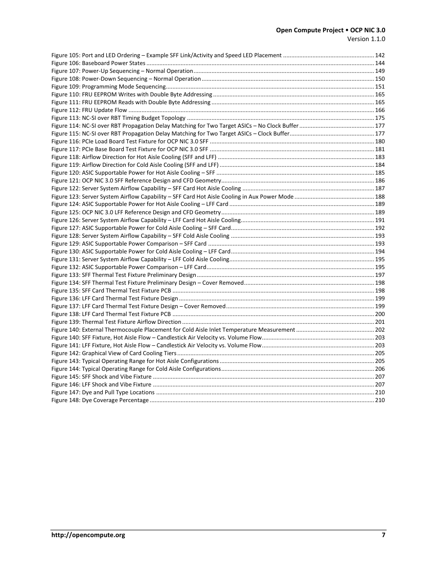
Open Compute Project  OCP NIC 3.0 Version 1.1.0 Figure 105: Port and LED Ordering – Example SFF Link/Activity and Speed LED Placement ........................................................ 142 Figure 106: Baseboard Power States ............................................................................................................................................ 144 Figure 107: Power-Up Sequencing – Normal Operation ............................................................................................................... 149 Figure 108: Power-Down Sequencing – Normal Operation .......................................................................................................... 150 Figure 109: Programming Mode Sequencing ................................................................................................................................ 151 Figure 110: FRU EEPROM Writes with Double Byte Addressing ................................................................................................... 165 Figure 111: FRU EEPROM Reads with Double Byte Addressing .................................................................................................... 165 Figure 112: FRU Update Flow ....................................................................................................................................................... 166 Figure 113: NC-SI over RBT Timing Budget Topology ................................................................................................................... 175 Figure 114: NC-SI over RBT Propagation Delay Matching for Two Target ASICs – No Clock Buffer .............................................. 177 Figure 115: NC-SI over RBT Propagation Delay Matching for Two Target ASICs – Clock Buffer.................................................... 177 Figure 116: PCIe Load Board Test Fixture for OCP NIC 3.0 SFF ..................................................................................................... 180 Figure 117: PCIe Base Board Test Fixture for OCP NIC 3.0 SFF ..................................................................................................... 181 Figure 118: Airflow Direction for Hot Aisle Cooling (SFF and LFF) ................................................................................................ 183 Figure 119: Airflow Direction for Cold Aisle Cooling (SFF and LFF) ............................................................................................... 184 Figure 120: ASIC Supportable Power for Hot Aisle Cooling – SFF ................................................................................................. 185 Figure 121: OCP NIC 3.0 SFF Reference Design and CFD Geometry.............................................................................................. 186 Figure 122: Server System Airflow Capability – SFF Card Hot Aisle Cooling ................................................................................. 187 Figure 123: Server System Airflow Capability – SFF Card Hot Aisle Cooling in Aux Power Mode ................................................. 188 Figure 124: ASIC Supportable Power for Hot Aisle Cooling – LFF Card ......................................................................................... 189 Figure 125: OCP NIC 3.0 LFF Reference Design and CFD Geometry .............................................................................................. 189 Figure 126: Server System Airflow Capability – LFF Card Hot Aisle Cooling .................................................................................. 191 Figure 127: ASIC Supportable Power for Cold Aisle Cooling – SFF Card ........................................................................................ 192 Figure 128: Server System Airflow Capability – SFF Cold Aisle Cooling ........................................................................................ 193 Figure 129: ASIC Supportable Power Comparison – SFF Card ...................................................................................................... 193 Figure 130: ASIC Supportable Power for Cold Aisle Cooling – LFF Card ........................................................................................ 194 Figure 131: Server System Airflow Capability – LFF Cold Aisle Cooling ......................................................................................... 195 Figure 132: ASIC Supportable Power Comparison – LFF Card ....................................................................................................... 195 Figure 133: SFF Thermal Test Fixture Preliminary Design ............................................................................................................. 197 Figure 134: SFF Thermal Test Fixture Preliminary Design – Cover Removed ................................................................................ 198 Figure 135: SFF Card Thermal Test Fixture PCB ............................................................................................................................ 198 Figure 136: LFF Card Thermal Test Fixture Design ........................................................................................................................ 199 Figure 137: LFF Card Thermal Test Fixture Design – Cover Removed ........................................................................................... 199 Figure 138: LFF Card Thermal Test Fixture PCB ............................................................................................................................ 200 Figure 139: Thermal Test Fixture Airflow Direction ...................................................................................................................... 201 Figure 140: External Thermocouple Placement for Cold Aisle Inlet Temperature Measurement ................................................ 202 Figure 140: SFF Fixture, Hot Aisle Flow – Candlestick Air Velocity vs. Volume Flow ..................................................................... 203 Figure 141: LFF Fixture, Hot Aisle Flow – Candlestick Air Velocity vs. Volume Flow ..................................................................... 203 Figure 142: Graphical View of Card Cooling Tiers ......................................................................................................................... 205 Figure 143: Typical Operating Range for Hot Aisle Configurations ............................................................................................... 205 Figure 144: Typical Operating Range for Cold Aisle Configurations .............................................................................................. 206 Figure 145: SFF Shock and Vibe Fixture ........................................................................................................................................ 207 Figure 146: LFF Shock and Vibe Fixture ........................................................................................................................................ 207 Figure 147: Dye and Pull Type Locations ...................................................................................................................................... 210 Figure 148: Dye Coverage Percentage .......................................................................................................................................... 210 http://opencompute.org 7
Open Compute Project  OCP NIC 3.0 Version 1.1.0 List of Tables Table 1: Acknowledgements – Current Contributors – By Company .............................................................................................. 11 Table 2: Acronyms .......................................................................................................................................................................... 14 Table 3: OCP 3.0 Form Factor Dimensions ...................................................................................................................................... 19 Table 4: Baseboard to OCP NIC Form Factor Compatibility Chart .................................................................................................. 19 Table 5: Example Non-NIC Use Cases ............................................................................................................................................. 21 Table 6: OCP NIC 3.0 Card Definitions............................................................................................................................................. 24 Table 7: OCP NIC 3.0 Line Side I/O Implementations ...................................................................................................................... 32 Table 8: Line Side I/O Cross Reference to Industry Standards ........................................................................................................ 32 Table 9: Bill of Materials for the SFF and LFF Faceplate Assemblies ............................................................................................... 35 Table 10: CTF Default Tolerances (SFF and LFF OCP NIC 3.0) .......................................................................................................... 55 Table 11: MAC Address Label Example 1 – Quad Port with Single Host, Single Managed Controller ............................................. 68 Table 12: MAC Address Label Example 2 – Octal Port with Single Host, Dual Managed Controller ............................................... 68 Table 13: MAC Address Label Example 3 – Quad Port with Dual Hosts, Dual Managed Controller................................................ 69 Table 14: MAC Address Label Example 4 – Single Port with Quad Host, Single Managed Controller ............................................. 70 Table 15: MAC Address Label Example 5 – Octal Port with Single Host, Octal Managed Controller .............................................. 70 Table 16: NIC Implementation Examples and 3D CAD .................................................................................................................... 71 Table 17: Contact Mating Positions for the Primary Connector ..................................................................................................... 74 Table 18: Contact Mating Positions for the Secondary Connector ................................................................................................. 76 Table 19: Right Angle Connector Options ....................................................................................................................................... 78 Table 20: Straddle Mount Connector Options ................................................................................................................................ 79 Table 21: Primary Connector Pin Definition (x16) (4C+) ................................................................................................................. 83 Table 22: Secondary Connector Pin Definition (x16) (4C) ............................................................................................................... 85 Table 23: Pin Descriptions – PCIe .................................................................................................................................................... 87 Table 24: Pin Descriptions – PCIe Present and Bifurcation Control Pins ......................................................................................... 92 Table 25: Pin Descriptions – SMBus ................................................................................................................................................ 95 Table 26: Pin Descriptions – NC-SI over RBT ................................................................................................................................... 96 Table 27: Pin Descriptions – Scan Chain ....................................................................................................................................... 104 Table 28: Scan Chain Timing Requirements – Baseboard Side ..................................................................................................... 106 Table 29: Scan Chain Timing Requirements – OCP NIC 3.0 Card Side ........................................................................................... 106 Table 30: Pin Descriptions – Scan Chain DATA_OUT Bit Definition............................................................................................... 107 Table 31: Pin Descriptions – Scan Chain DATA_IN Bit Definition .................................................................................................. 107 Table 32: Pin Descriptions – Power............................................................................................................................................... 113 Table 33: Pin Descriptions – USB 2.0 – Primary Connector only ................................................................................................... 118 Table 34: Pin Descriptions – UART – Secondary Connector Only.................................................................................................. 120 Table 35: Pin Descriptions – RFU[1:4] ........................................................................................................................................... 122 Table 36: PCIe Bifurcation Decoder for x32, x16, x8, x4, x2 and x1 Card Widths.......................................................................... 125 Table 37: PCIe REFCLK and PERST Associations ............................................................................................................................ 132 Table 38: SFF PCIe Link / REFCLKn / PERSTn mapping for 1, 2 and 4 Links ................................................................................... 132 Table 39: LFF PCIe Link / REFCLKn / PERSTn mapping for 1, 2, 4 and 8 Links................................................................................ 132 Table 40: OCP NIC 3.0 Card LED Configuration with Two Physical LEDs per Port ......................................................................... 140 Table 41: Available Card Functions per Power State .................................................................................................................... 145 Table 42: Baseboard Power Supply Rail Requirements – Slot Power Envelopes .......................................................................... 147 Table 43: Power Sequencing Parameters ..................................................................................................................................... 151 Table 44: Digital I/O DC specifications .......................................................................................................................................... 153 Table 45: Digital I/O AC specifications .......................................................................................................................................... 153 Table 46: OCP NIC 3.0 Management Implementation Definitions ................................................................................................ 154 Table 47: Sideband Management Interface and Transport Requirements ................................................................................... 154 Table 48: NC-SI Traffic Requirements ........................................................................................................................................... 155 Table 49: MC MAC Address Provisioning Requirements .............................................................................................................. 155 Table 50: Threshold Severity Level vs Example Threshold Values ................................................................................................ 158 Table 51: Temperature Reporting Requirements ......................................................................................................................... 158 Table 52: Power Consumption Reporting Requirements.............................................................................................................. 160 Table 53: Pluggable Module Status Reporting Requirements ...................................................................................................... 161 Table 54: Management and Pre-OS Firmware Inventory and Update Requirements .................................................................. 161 Table 55: Slot_ID[1:0] to Package ID[2:0] Mapping ...................................................................................................................... 163 Table 56: FRU EEPROM Address Map ........................................................................................................................................... 164 Table 57: FRU EEPROM Record – OEM Record 0xC0, Offset 0x00 ................................................................................................ 167 http://opencompute.org 8
分享到:
收藏