logo资料库

TC358867XBG_Rev010_20180125a.pdf

第1页 / 共267页
第2页 / 共267页
第3页 / 共267页
第4页 / 共267页
第5页 / 共267页
第6页 / 共267页
第7页 / 共267页
第8页 / 共267页
资料共267页,剩余部分请下载后查看
1. Overview
2. Features
3. External Pins
3.1. TC358867 External Pins
3.2. TC358867 Ball Mapping
4. Function of Major Blocks
4.1. MIPI DSI Rx
4.1.1. Video Streaming
4.1.1.1. Video Transmission
4.1.1.2. DSI Packets for Video Transmission
4.1.1.3. Pixel Format
4.1.2. DSI Write/Read accesses to Chip Configuration Registers
4.1.2.1. Write Access
4.1.2.1.1. Read Access
4.1.3. Exit/Enter chip power-down state using DSI interface
4.1.4. Reverse Low Power Transmission
4.1.5. DSI Packet Type Support
4.2. MIPI DPI Rx
4.2.1. Video Streaming
4.2.1.1. Video Transmission
4.2.1.2. Pixel Format
4.3. I2S Audio Rx
4.3.1. Audio Transmission & Alignment modes
4.3.2. Channel slots, Sample bit-width and bit clock
4.3.2.1. Sample Width possibilities
4.3.3. I2S Rx to DisplayPort Tx Interface
4.3.3.1. Audio Info Frame packet
4.3.3.2. Audio Time Stamp packet
4.3.3.3. Audio Stream packet
4.3.3.3.1. Format of 4-byte Per Channel Audio Stream Payload word in DP frame
4.3.4. Audio Stream Start / Stop Procedure
4.3.4.1. Audio streaming Start Procedure
4.3.4.2. Audio Stream Stop Procedure
4.4. DisplayPort Tx
4.4.1. Main Channel Overview
4.4.1.1. Main Channel – Digital Controller
4.4.1.1.1. Main Channel – Clocks
4.4.1.1.2. Main Channel – Timing Signals
4.4.1.1.3. Main Channel – Video Data
4.4.1.1.4. Main Channel – Audio & Info Data
4.4.1.2. Main Channel – Analog PHY
4.4.2. Aux Channel Overview
4.4.2.1. Aux Channel – Digital Controller
4.4.2.1.1. Register access based transactions
4.4.2.1.1.1. Write transactions
4.4.2.1.1.2. Read transactions
4.4.2.1.2. I2C over AUX based transactions
4.4.2.2. Aux Channel – Analog PHY
4.4.3. Display Port Link Establishment
4.4.3.1. Sink DPCD Read
4.4.3.2. Link Training
4.4.3.2.1. Fast Link Training
4.4.3.2.2. Host Controlled Link Training
4.4.3.2.3. TC358867 Controlled Link Training
4.5. Parallel Output Mode
4.6. GPIO Interface
4.7. I2C Slave Interface
4.7.1. Providing Register Address over I2C Bus
4.7.2. I2C Write Access Translation
4.7.3. I2C Read Access Translation
4.8. Interrupt Interface
4.8.1. Interrupt Assertion
4.8.1.1. GPIO0 & GPIO1 Based Interrupt Assertion
4.8.2. Interrupt Handling
4.9. Internal Test Pattern (Color Bar) Generator
4.10. HDCP Support (Optional)
4.10.1. HDCP encryption modules
4.11. Reset
4.12. Boot-Strap & State of TC358867 chip after Reset
4.12.1. MODE[0]: Clock Source Selection
4.12.2. MODE[1]: DSI Reference Clock Source Division Selection
4.12.3. I2C Slave Address Selection
4.12.4. Miscellaneous
4.13. Clocks
4.13.1. Updating PLL parameters
4.13.2. Down-spreading of Link Frequency (Spread Spectrum)
4.14. Power on/off Procedure
4.15. Register Accesses from Host
4.15.1. TC358867 register space accesses
4.15.1.1. TC358867 register accesses from DSI
4.15.1.1.1. Sys_PllParam register update access from DSI
4.15.1.2. DP PHY internal register space accesses
4.15.2. DP Sink register space accesses
4.15.2.1. Native Aux access
4.15.2.1.1. Register Write
4.15.2.1.2. Register Read
4.15.2.2. I2C Aux access
4.15.2.2.1. Register Write through TC358867 register access
4.15.2.2.2. Register Read through TC358867 register access
4.16. Video Transmission over DP link
4.16.1. DSI to DisplayPort Tx
4.16.2. DPI to DisplayPort Tx
4.16.3. Pixel Format Translation
4.16.4. Magic Square Algorithm
4.16.5. DP programming requirement
4.16.6. TC358867 transfer paths
4.17. Power Management
4.17.1. Power State transitions
5. RegFile Block (Reg)
5.1. Register Map
5.1.1. Address Map Summary
5.1.2. Register Map
5.2. Register access protocol
5.2.1. Register Write
5.2.2. Register Read
5.3. DSI Registers
5.3.1. DSI PHY Layer Registers
5.3.1.1. D0W_DPHYCONTTX Register
5.3.1.2. CLW_DPHYCONTRX Register
5.3.1.3. D0W_DPHYCONTRX Register
5.3.1.4. D1W_DPHYCONTRX Register
5.3.1.5. D2W_DPHYCONTRX Register
5.3.1.6. D3W_DPHYCONTRX Register
5.3.1.7. COM_DPHYCONTRX Register
5.3.1.8. CLW_CNTRL Register
5.3.1.9. D0W_CNTRL Register
5.3.1.10. D1W_CNTRL Register
5.3.1.11. D2W_CNTRL Register
5.3.1.12. D3W_CNTRL Register
5.3.1.13. DFT Mode Control Register
5.3.2. DSI PPI Layer Registers
5.3.2.1. PPI_STARTPPI Register
5.3.2.2. PPI_BUSYPPI Register
5.3.2.3. PPI_LINEINITCNT Register
5.3.2.4. PPI_LPTXTIMECNT Register
5.3.2.5. PPI_LANEENABLE Register
5.3.2.6. PPI_TX_RX_TA Register
5.3.2.7. PPI_CLS_ATMR Register
5.3.2.8. PPI_D0S_ATMR Register
5.3.2.9. PPI_D1S_ATMR Register
5.3.2.10. PPI_D2S_ATMR Register
5.3.2.11. PPI_D3S_ATMR Register
5.3.2.12. PPI_D0S_CLRSIPOCOUNT Register
5.3.2.13. PPI_D1S_CLRSIPOCOUNT Register
5.3.2.14. PPI_D2S_CLRSIPOCOUNT Register
5.3.2.15. PPI_D3S_CLRSIPOCOUNT Register
5.3.2.16. CLS_PRE Register
5.3.2.17. D0S_PRE Register
5.3.2.18. D1S_PRE Register
5.3.2.19. D2S_PRE Register
5.3.2.20. D3S_PRE Register
5.3.2.21. CLS_PREP Register
5.3.2.22. D0S_PREP Register
5.3.2.23. D1S_PREP Register
5.3.2.24. D2S_PREP Register
5.3.2.25. D3S_PREP Register
5.3.2.26. CLS_ZERO Register
5.3.2.27. D0S_ZERO Register
5.3.2.28. D1S_ZERO Register
5.3.2.29. D2S_ZERO Register
5.3.2.30. D3S_ZERO Register
5.3.2.31. PPI_CLRFLG Register
5.3.2.32. PPI_CLRSIPO Register
5.3.2.33. HSTIMEOUT Register
5.3.2.34. HSTIMEOUTENABLE Register
5.3.3. DSI Protocol Layer Registers
5.3.3.1. DSI_STARTDSI Register
5.3.3.2. DSI_BUSYDSI Register
5.3.3.3. DSI_LANEENABLE Register
5.3.3.4. DSI_LANESTATUS0 Register
5.3.3.5. DSI_LANESTATUS1 Register
5.3.3.6. DSI_INTSTATUS Register
5.3.3.7. DSI_INTMASK Register
5.3.3.8. DSI_INTCLR Register
5.3.3.9. DSI_LPTXTO Register
5.3.4. DSI General Registers
5.3.4.1. DSIERRCNT Register
5.3.5. DSI Application Layer Registers
5.3.5.1. Application Layer Control Register
5.3.5.2. DSI Read Packet Length Register
5.4. DPI Registers
5.4.1. DPIPXLFMT
5.5. Parallel Output Registers
5.5.1. POCTRL
5.6. Video Path0 Configuration Registers
5.6.1. Video Path0 Control (VPCTRL0)
5.6.2. Horizontal Timing Control0 Register 1 (HTIM01)
5.6.3. Horizontal Timing Control0 Register 2 (HTIM02)
5.6.4. Vertical Timing Control0 Register 1 (VTIM01)
5.6.5. Vertical Timing Control0 Register 2 (VTIM02)
5.6.6. Video Frame Timing Upload Enable0 (VFUEN0)
5.7. System register description
5.7.1. Chip ID and Revision Register
5.7.2. SYS BOOT Register
5.7.3. SYS Status Register
5.7.4. SYS Reset_Enable Register
5.7.5. SYS Control Register
5.7.6. DisplayPort Clock Registers
5.7.6.1. DP0_VidMNGen0
5.7.6.2. DP0_VidMNGen1
5.7.6.3. DP0_VMNGenStatus
5.7.6.4. DP0_AudMNGen0
5.7.6.5. DP0_AudMNGen1
5.7.6.6. DP0_AMNGenStatus
5.8. I2C Registers
5.8.1. I2C Timing Control and Enable Register
5.9. GPIO Registers
5.9.1. GPIO Mode Register
5.9.2. GPIO Control Register
5.9.3. GPIO Output Register
5.9.4. GPIO Input Register
5.10. Interrupt Registers
5.10.1. INTCTL_G Register
5.10.2. INTSTS_G Register
5.10.3. INT_GP0_LCNT Register
5.10.4. INT_GP1_LCNT Register
5.11. DP – DisplayPort Registers
5.11.1. DisplayPort0 Control Registers
5.11.1.1. DP0Ctl
5.11.2. DisplayPort0 Main Channel Registers
5.11.2.1. DP0_SecSample
5.11.2.2. DP0_VidSyncDelay
5.11.2.3. DP0_TotalVal
5.11.2.4. DP0_StartVal
5.11.2.5. DP0_ActiveVal
5.11.2.6. DP0_SyncVal
5.11.2.7. DP0_Misc
5.11.3. DisplayPort0 AUX Channel Registers
5.11.3.1. DP0_AuxCfg0
5.11.3.2. DP0_AuxCfg1
5.11.3.3. DP0_AuxAddr
5.11.3.4. DP0_AuxWData0
5.11.3.5. DP0_AuxWData1
5.11.3.6. DP0_AuxWData2
5.11.3.7. DP0_AuxWData3
5.11.3.8. DP0_AuxRData0
5.11.3.9. DP0_AuxRData1
5.11.3.10. DP0_AuxRData2
5.11.3.11. DP0_AuxRData3
5.11.3.12. DP0_AuxStatus
5.11.3.13. DP0_AuxI2CAdr
5.11.4. DisplayPort0 Link Training Control & Status Registers
5.11.4.1. DP0_SrcCtrl Register
5.11.4.2. DP0_LTStat Register
5.11.4.3. DP0_SnkLTChReq Register
5.11.4.4. DP0_LTLoopCtrl Register
5.11.4.5. DP0_SnkLTCtrl
5.11.4.6. DP0_TPatDat0
5.11.4.7. DP0_TPatDat1
5.11.4.8. DP0_TPatDat2
5.11.4.9. DP0_TPatDat3
5.11.5. DisplayPort Audio Registers
5.11.5.1. AudCfg0
5.11.5.2. AudCfg1
5.11.5.3. AudIFData0
5.11.5.4. AudIFData1
5.11.5.5. AudIFData2
5.11.5.6. AudIFData3
5.11.5.7. AudIFData4
5.11.5.8. AudIFData5
5.11.5.9. AudIFData6
5.11.6. DisplayPort PHY Registers
5.11.6.1. DP_PHY_Ctrl Register
5.11.6.2. DP_PHY_CFG_WR Register
5.11.6.3. DP_PHY_CFG_RD Register
5.11.6.4. DP0_AUX_PHY_Ctrl Register
5.11.6.5. DP0_Main_PHY_Dbg Debug Register
5.12. I2S Registers
5.12.1. I2SCfg
5.12.2. I2SCH0Stat0
5.12.3. I2SCH0Stat1
5.12.4. I2SCH0Stat2
5.12.5. I2SCH0Stat3
5.12.6. I2SCH0Stat4
5.12.7. I2SCH0Stat5
5.12.8. I2SCH1Stat0
5.12.9. I2SCH1Stat1
5.12.10. I2SCH1Stat2
5.12.11. I2SCH1Stat3
5.12.12. I2SCH1Stat4
5.12.13. I2SCH1Stat5
5.13. PLL Registers
5.13.1. DP0_PLLCTRL Register
5.13.2. PXL_PLLCTRL Register
5.13.3. PXL_PLLPARAM Register
5.13.4. SYS_PLLPARAM Register
5.14. HDCP Block Registers
5.14.1. HDCP Control Register (HDCPCTRL)
5.14.2. HDCP Time Out Counter Register (HDCPTOCNT)
5.14.3. HDCP Status Register (HDCPSTAT)
5.14.4. HDCP AN SEED LSB Register (HDCPANSEEDLSB)
5.14.5. HDCP AN SEED MSB Register (HDCPANSEEDMSB)
5.14.6. HDCP AN LSB Register (HDCPANLSB)
5.14.7. HDCP AN MSB Register (HDCPANMSB)
5.14.8. HDCP AKSV LSB Register (HDCPAKSVLSB)
5.14.9. HDCP AKSV MSB Register (HDCPAKSVMSB)
5.14.10. HDCP0 BKSV LSB Register (HDCP0BKSVLSB)
5.14.11. HDCP BKSV MSB Register (HDCPBKSVMSB)
5.14.12. HDCP Rx R0 Register (HDCPRxR0)
5.15. Debug Registers
5.15.1. Test control register (TestCtl)
5.15.2. PLL_DBG Debug Register
6. Package
7. Electrical Characteristics
7.1. Absolute Maximum Ratings
7.2. Recommended Operating Condition
7.3. DC Electrical Specification
7.4. Power Consumption
8. Timing Definitions
8.1. MIPI DSI Timings
8.1.1. LP Transmitter DC Specifications
8.1.2. HS Receiver DC Specifications
8.1.3. LP Receiver DC Specifications
8.1.4. LP Transmitter AC Specifications
8.1.5. HS Receiver AC Specifications
8.1.6. LP Receiver AC Specifications
8.2. DPI Interface Timings
8.3. Parallel Output Interface Timings
8.4. I2S Audio Interface Timings
8.5. DisplayPort Timings
8.6. I2C Timings
RESTRICTIONS ON PRODUCT USE
Preliminary TC358867XBG DSI 2(to) Display Port Converter TC358867 Functional Specifications Revision 0.10 2018-01 1 / 267 2018-01-25 Rev. 0.10 © 2018 Toshiba Electronic Devices & Storage Corporation
Preliminary TC358867XBG ● MIPI is a trademark of MIPI Alliance, Inc. ● DisplayPort is trademark owned by the Video Electronics Standards Association (VESA®) in the United States and other countries. ● All other company names, product names, and service names may be trademarks of their respective companies. 2 / 267 2018-01-25
Preliminary TC358867XBG NOTICE OF DISCLAIMER The material contained herein is not a license, either expressly or impliedly, to any IPR owned or controlled by any of the authors or developers of this material or MIPI®. The material contained herein is provided on an “AS IS” basis and to the maximum extent permitted by applicable law, this material is provided AS IS AND WITH ALL FAULTS, and the authors and developers of this material and MIPI® hereby disclaim all other warranties and conditions, either express, implied or statutory, including, but not limited to, any (if any) implied warranties, duties or conditions of merchantability, of fitness for a particular purpose, of accuracy or completeness of responses, of results, of workmanlike effort, of lack of viruses, and of lack of negligence. All materials contained herein are protected by copyright laws, and may not be reproduced, republished, distributed, transmitted, displayed, broadcast or otherwise exploited in any manner without the express prior written permission of MIPI® Alliance. MIPI®, MIPI® Alliance and the dotted rainbow arch and all related trademarks, tradenames, and other intellectual property are the exclusive property of MIPI® Alliance and cannot be used without its express prior written permission. ALSO, THERE IS NO WARRANTY OF CONDITION OF TITLE, QUIET ENJOYMENT, QUIET POSSESSION, CORRESPONDENCE TO DESCRIPTION OR NON-INFRINGEMENT WITH REGARD TO THIS MATERIAL OR THE CONTENTS OF THIS DOCUMENT. IN NO EVENT WILL ANY AUTHOR OR DEVELOPER OF THIS MATERIAL OR THE CONTENTS OF THIS DOCUMENT OR MIPI® BE LIABLE TO ANY OTHER PARTY FOR THE COST OF PROCURING SUBSTITUTE GOODS OR SERVICES, LOST PROFITS, LOSS OF USE, LOSS OF DATA, OR ANY INCIDENTAL, CONSEQUENTIAL, DIRECT, INDIRECT, OR SPECIAL DAMAGES WHETHER UNDER CONTRACT, TORT, WARRANTY, OR OTHERWISE, ARISING IN ANY WAY OUT OF THIS OR ANY OTHER AGREEMENT, SPECIFICATION OR DOCUMENT RELATING TO THIS MATERIAL, WHETHER OR NOT SUCH PARTY HAD ADVANCE NOTICE OF THE POSSIBILITY OF SUCH DAMAGES. Without limiting the generality of this Disclaimer stated above, the user of the contents of this Document is further notified that MIPI®: (a) does not evaluate, test or verify the accuracy, soundness or credibility of the contents of this Document; (b) does not monitor or enforce compliance with the contents of this Document; and (c) does not certify, test, or in any manner investigate products or services or any claims of compliance with the contents of this Document. The use or implementation of the contents of this Document may involve or require the use of intellectual property rights ("IPR") including (but not limited to) patents, patent applications, or copyrights owned by one or more parties, whether or not Members of MIPI®. MIPI® does not make any search or investigation for IPR, nor does MIPI® require or request the disclosure of any IPR or claims of IPR as respects the contents of this Document or otherwise. Questions pertaining to this document, or the terms or conditions of its provision, should be addressed to: MIPI® Alliance, Inc. c/o IEEE-ISTO 445 Hoes Lane Piscataway, NJ 08854 Attn: Board Secretary This Notice of Disclaimer applies to all DSI input and processing paths related descriptions throughout this document. Copyright © 2005-2010 MIPI® Alliance, Inc. All rights reserved. MIPI® Alliance Member Confidential. All rights reserved. This material is reprinted with the permission of the MIPI® Alliance, Inc. No part(s) of this document may be disclosed, reproduced or used for any purpose other than as needed to support the use of the products of Toshiba Cooperation and its subsidiaries and affiliates. 3 / 267 2018-01-25
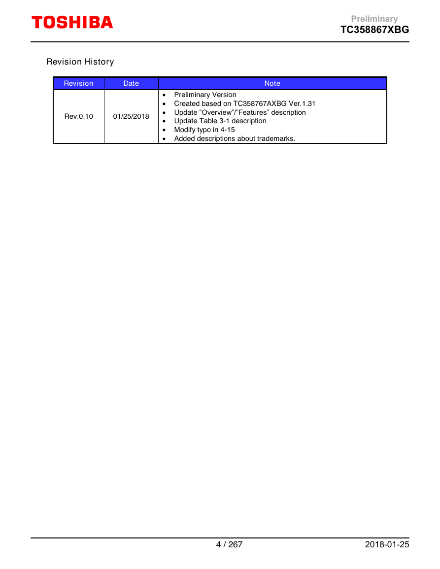
Preliminary TC358867XBG Revision History Revision Date Note  Preliminary Version  Created based on TC358767AXBG Ver.1.31  Update “Overview”/”Features” description  Update Table 3-1 description  Modify typo in 4-15  Added descriptions about trademarks. Rev.0.10 01/25/2018 4 / 267 2018-01-25
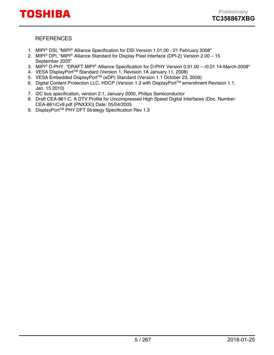
Preliminary TC358867XBG REFERENCES 1. MIPI® DSI, "MIPI® Alliance Specification for DSI Version 1.01.00 - 21 February 2008" 2. MIPI® DPI, “MIPI® Alliance Standard for Display Pixel Interface (DPI-2) Version 2.00 – 15 September 2005” 3. MIPI® D-PHY, “DRAFT MIPI® Alliance Specification for D-PHY Version 0.91.00 – r0.01 14-March-2008" 4. VESA DisplayPortTM Standard (Version 1, Revision 1A January 11, 2008) 5. VESA Embedded DisplayPortTM (eDP) Standard (Version 1.1 October 23, 2009) 6. Digital Content Protection LLC, HDCP (Version 1.3 with DisplayPortTM amendment Revision 1.1, Jan. 15 2010) 7. I2C bus specification, version 2.1, January 2000, Philips Semiconductor 8. Draft CEA-861-C, A DTV Profile for Uncompressed High Speed Digital Interfaces (Doc. Number: CEA-861rCv9.pdf (PNXXX)) Date: 05/04/2005 9. DisplayPortTM PHY DFT Strategy Specification Rev 1.3 5 / 267 2018-01-25
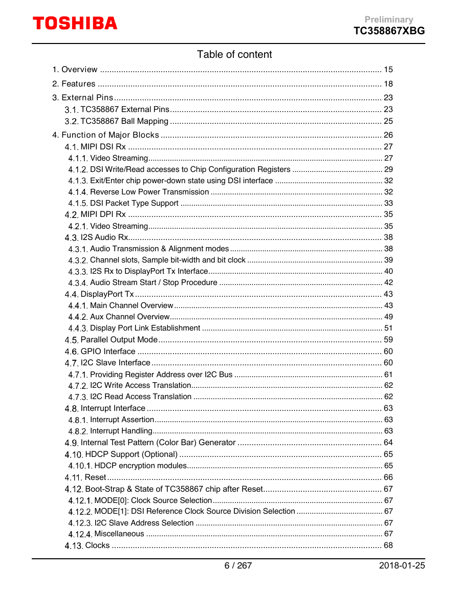
Preliminary TC358867XBG Table of content 1. Overview ......................................................................................................................... 15 2. Features .......................................................................................................................... 18 3. External Pins ................................................................................................................... 23 TC358867 External Pins ........................................................................................... 23 TC358867 Ball Mapping ........................................................................................... 25 4. Function of Major Blocks ............................................................................................... 26 MIPI DSI Rx ............................................................................................................. 27 Video Streaming ............................................................................................................. 27 DSI Write/Read accesses to Chip Configuration Registers .......................................... 29 Exit/Enter chip power-down state using DSI interface .................................................. 32 Reverse Low Power Transmission ................................................................................ 32 DSI Packet Type Support .............................................................................................. 33 MIPI DPI Rx ............................................................................................................. 35 Video Streaming ............................................................................................................. 35 I2S Audio Rx............................................................................................................. 38 Audio Transmission & Alignment modes ....................................................................... 38 Channel slots, Sample bit-width and bit clock ............................................................... 39 I2S Rx to DisplayPort Tx Interface ................................................................................. 40 Audio Stream Start / Stop Procedure ............................................................................ 42 DisplayPort Tx .......................................................................................................... 43 Main Channel Overview ................................................................................................. 43 Aux Channel Overview................................................................................................... 49 Display Port Link Establishment .................................................................................... 51 Parallel Output Mode ................................................................................................ 59 GPIO Interface ......................................................................................................... 60 I2C Slave Interface ................................................................................................... 60 Providing Register Address over I2C Bus ..................................................................... 61 I2C Write Access Translation ......................................................................................... 62 I2C Read Access Translation ........................................................................................ 62 Interrupt Interface ..................................................................................................... 63 Interrupt Assertion .......................................................................................................... 63 Interrupt Handling ........................................................................................................... 63 Internal Test Pattern (Color Bar) Generator .............................................................. 64 HDCP Support (Optional) ....................................................................................... 65 HDCP encryption modules ........................................................................................... 65 Reset ...................................................................................................................... 66 Boot-Strap & State of TC358867 chip after Reset ................................................... 67 MODE[0]: Clock Source Selection ............................................................................... 67 MODE[1]: DSI Reference Clock Source Division Selection ........................................ 67 I2C Slave Address Selection ....................................................................................... 67 Miscellaneous .............................................................................................................. 67 Clocks .................................................................................................................... 68 6 / 267 2018-01-25
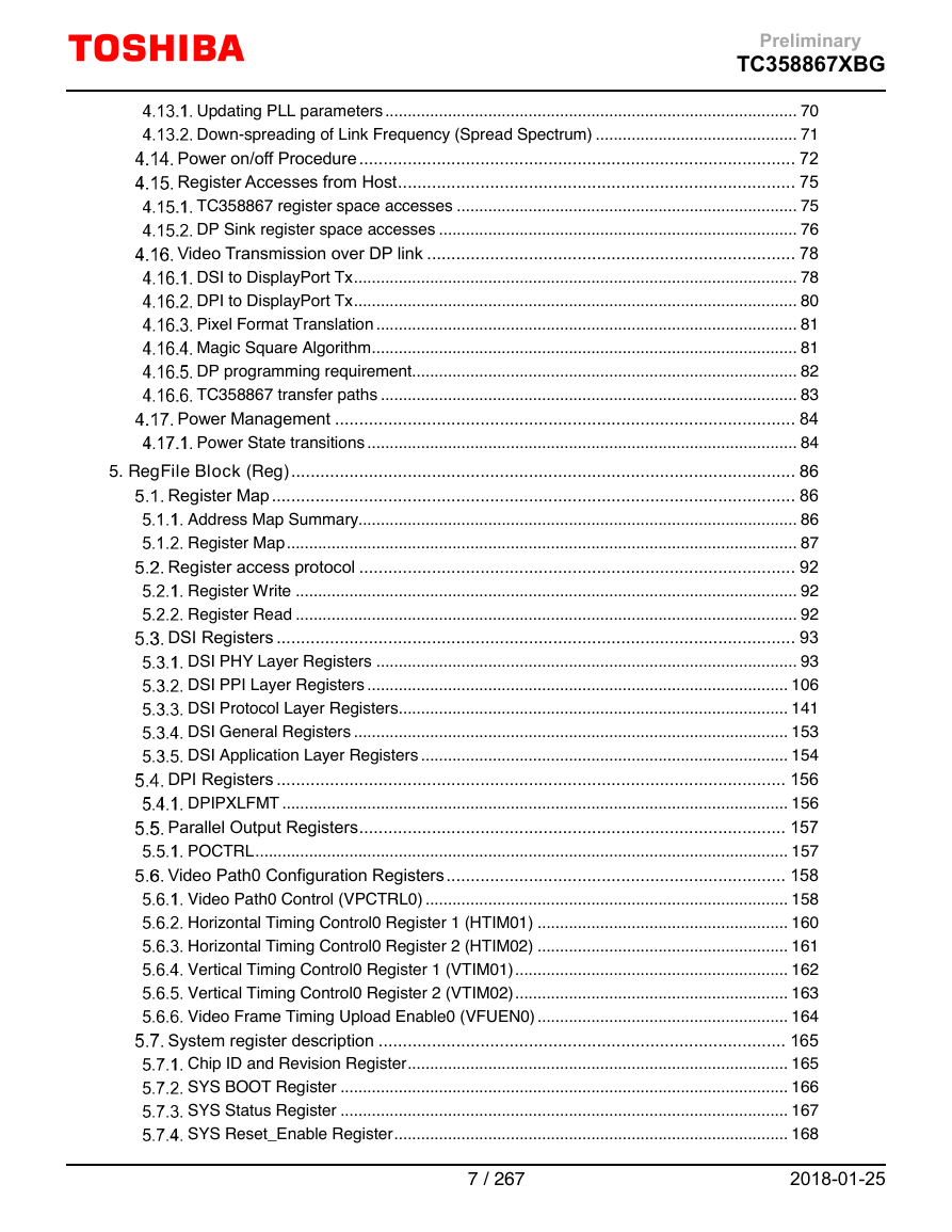
Preliminary TC358867XBG Updating PLL parameters ............................................................................................ 70 Down-spreading of Link Frequency (Spread Spectrum) ............................................. 71 Power on/off Procedure .......................................................................................... 72 Register Accesses from Host .................................................................................. 75 TC358867 register space accesses ............................................................................ 75 DP Sink register space accesses ................................................................................ 76 Video Transmission over DP link ............................................................................ 78 DSI to DisplayPort Tx ................................................................................................... 78 DPI to DisplayPort Tx ................................................................................................... 80 Pixel Format Translation .............................................................................................. 81 Magic Square Algorithm ............................................................................................... 81 DP programming requirement...................................................................................... 82 TC358867 transfer paths ............................................................................................. 83 Power Management ............................................................................................... 84 Power State transitions ................................................................................................ 84 5. RegFile Block (Reg) ........................................................................................................ 86 Register Map ............................................................................................................ 86 Address Map Summary.................................................................................................. 86 Register Map .................................................................................................................. 87 Register access protocol .......................................................................................... 92 Register Write ................................................................................................................ 92 Register Read ................................................................................................................ 92 DSI Registers ........................................................................................................... 93 DSI PHY Layer Registers .............................................................................................. 93 DSI PPI Layer Registers .............................................................................................. 106 DSI Protocol Layer Registers ....................................................................................... 141 DSI General Registers ................................................................................................. 153 DSI Application Layer Registers .................................................................................. 154 DPI Registers ......................................................................................................... 156 DPIPXLFMT ................................................................................................................. 156 Parallel Output Registers ........................................................................................ 157 POCTRL ....................................................................................................................... 157 Video Path0 Configuration Registers ...................................................................... 158 Video Path0 Control (VPCTRL0) ................................................................................. 158 Horizontal Timing Control0 Register 1 (HTIM01) ........................................................ 160 Horizontal Timing Control0 Register 2 (HTIM02) ........................................................ 161 Vertical Timing Control0 Register 1 (VTIM01) ............................................................. 162 Vertical Timing Control0 Register 2 (VTIM02) ............................................................. 163 Video Frame Timing Upload Enable0 (VFUEN0) ........................................................ 164 System register description .................................................................................... 165 Chip ID and Revision Register ..................................................................................... 165 SYS BOOT Register .................................................................................................... 166 SYS Status Register .................................................................................................... 167 SYS Reset_Enable Register ........................................................................................ 168 7 / 267 2018-01-25
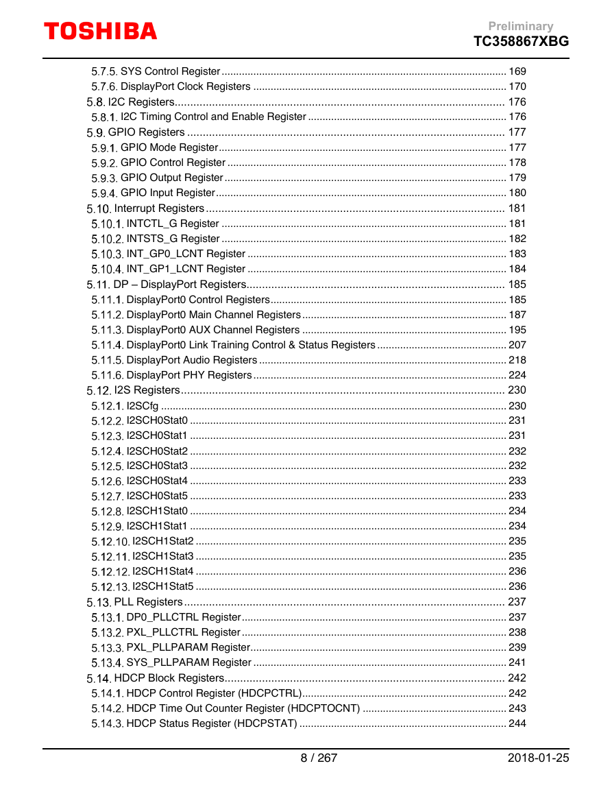
Preliminary TC358867XBG SYS Control Register ................................................................................................... 169 DisplayPort Clock Registers ........................................................................................ 170 I2C Registers.......................................................................................................... 176 I2C Timing Control and Enable Register ..................................................................... 176 GPIO Registers ...................................................................................................... 177 GPIO Mode Register .................................................................................................... 177 GPIO Control Register ................................................................................................. 178 GPIO Output Register .................................................................................................. 179 GPIO Input Register ..................................................................................................... 180 Interrupt Registers ................................................................................................ 181 INTCTL_G Register ................................................................................................... 181 INTSTS_G Register ................................................................................................... 182 INT_GP0_LCNT Register .......................................................................................... 183 INT_GP1_LCNT Register .......................................................................................... 184 DP – DisplayPort Registers................................................................................... 185 DisplayPort0 Control Registers .................................................................................. 185 DisplayPort0 Main Channel Registers ....................................................................... 187 DisplayPort0 AUX Channel Registers ....................................................................... 195 DisplayPort0 Link Training Control & Status Registers ............................................. 207 DisplayPort Audio Registers ...................................................................................... 218 DisplayPort PHY Registers ........................................................................................ 224 I2S Registers ........................................................................................................ 230 I2SCfg ........................................................................................................................ 230 I2SCH0Stat0 .............................................................................................................. 231 I2SCH0Stat1 .............................................................................................................. 231 I2SCH0Stat2 .............................................................................................................. 232 I2SCH0Stat3 .............................................................................................................. 232 I2SCH0Stat4 .............................................................................................................. 233 I2SCH0Stat5 .............................................................................................................. 233 I2SCH1Stat0 .............................................................................................................. 234 I2SCH1Stat1 .............................................................................................................. 234 I2SCH1Stat2 ............................................................................................................ 235 I2SCH1Stat3 ............................................................................................................ 235 I2SCH1Stat4 ............................................................................................................ 236 I2SCH1Stat5 ............................................................................................................ 236 PLL Registers ....................................................................................................... 237 DP0_PLLCTRL Register ............................................................................................ 237 PXL_PLLCTRL Register ............................................................................................ 238 PXL_PLLPARAM Register ......................................................................................... 239 SYS_PLLPARAM Register ........................................................................................ 241 HDCP Block Registers .......................................................................................... 242 HDCP Control Register (HDCPCTRL) ....................................................................... 242 HDCP Time Out Counter Register (HDCPTOCNT) .................................................. 243 HDCP Status Register (HDCPSTAT) ........................................................................ 244 8 / 267 2018-01-25
分享到:
收藏