Open NAND Flash Interface Specification
Revision 2.0
27-February-2008
Hynix Semiconductor
Intel Corporation
Micron Technology, Inc.
Phison Electronics Corp.
Sony Corporation
Spansion
STMicroelectronics
�
SPECIFICATION DISCLAIMER
“AS
This 2.0 revision of the Open NAND Flash Interface specification ("Final Specification") is
available for download at www.onfi.org.
IS PROVIDED TO YOU
IS” WITH NO WARRANTIES
THIS SPECIFICATION
WHATSOEVER,
INCLUDING ANY WARRANTY OF MERCHANTABILITY, NON-
INFRINGEMENT, OR FITNESS FOR ANY PARTICULAR PURPOSE. THE AUTHORS OF THIS
SPECIFICATION DISCLAIM ALL LIABILITY, INCLUDING LIABILITY FOR INFRINGEMENT OF
ANY PROPRIETARY RIGHTS, RELATING TO USE OR IMPLEMNETATION OF INFORMATION
IN THIS SPECIFICATION. THE AUTHORS DO NOT WARRANT OR REPRESENT THAT SUCH
USE WILL NOT INFRINGE SUCH RIGHTS. THE PROVISION OF THIS SPECIFICATION TO
YOU DOES NOT PROVIDE YOU WITH ANY LICENSE, EXPRESS OR IMPLIED, BY
ESTOPPEL OR OTHERWISE, TO ANY INTELLECTUAL PROPERTY RIGHTS.
Copyright 2005-2008, Hynix Semiconductor, Intel Corporation, Micron Technology, Inc., Phison
Electronics Corp., Sony Corporation, Spansion, STMicroelectronics. All rights reserved.
For more information about ONFI, refer to the ONFI Workgroup website at www.onfi.org.
All product names are trademarks, registered trademarks, or servicemarks of their respective
owners.
ONFI Workgroup Technical Editor:
Amber Huffman
Intel Corporation
2111 NE 25th Ave M/S JF2-53
Hillsboro, OR 97124 USA
Tel: (503) 264-7929
Email: amber.huffman@intel.com
ii
�
2.
3.
4.
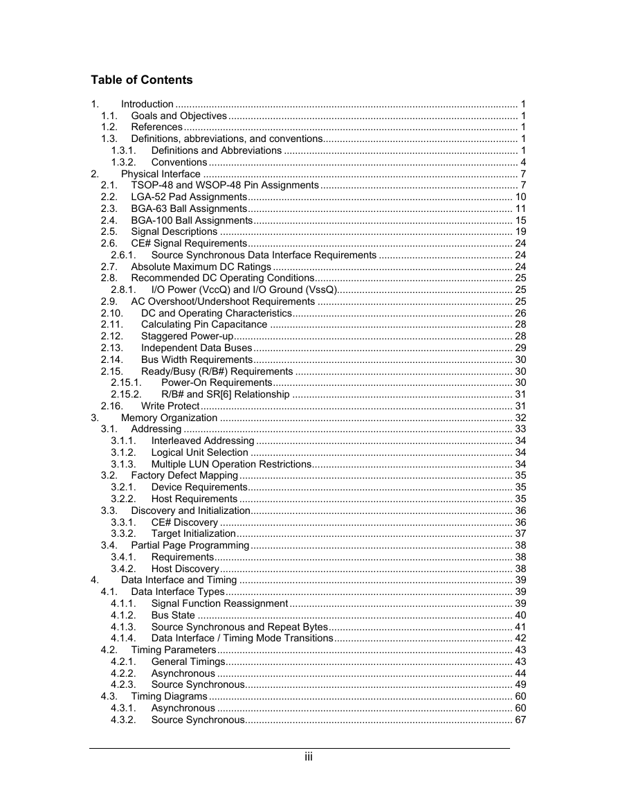
Table of Contents
1.
2.8.1.
2.15.1.
2.15.2.
Introduction ........................................................................................................................... 1
1.1. Goals and Objectives........................................................................................................ 1
1.2. References........................................................................................................................ 1
1.3. Definitions, abbreviations, and conventions...................................................................... 1
1.3.1. Definitions and Abbreviations .................................................................................... 1
1.3.2. Conventions ............................................................................................................... 4
Physical Interface ................................................................................................................. 7
2.1. TSOP-48 and WSOP-48 Pin Assignments....................................................................... 7
2.2. LGA-52 Pad Assignments............................................................................................... 10
2.3. BGA-63 Ball Assignments............................................................................................... 11
2.4. BGA-100 Ball Assignments............................................................................................. 15
2.5. Signal Descriptions ......................................................................................................... 19
2.6. CE# Signal Requirements............................................................................................... 24
2.6.1. Source Synchronous Data Interface Requirements ................................................ 24
2.7. Absolute Maximum DC Ratings ...................................................................................... 24
2.8. Recommended DC Operating Conditions....................................................................... 25
I/O Power (VccQ) and I/O Ground (VssQ)............................................................... 25
2.9. AC Overshoot/Undershoot Requirements ...................................................................... 25
DC and Operating Characteristics............................................................................... 26
2.10.
2.11.
Calculating Pin Capacitance ....................................................................................... 28
2.12.
Staggered Power-up.................................................................................................... 28
Independent Data Buses............................................................................................. 29
2.13.
2.14.
Bus Width Requirements............................................................................................. 30
2.15.
Ready/Busy (R/B#) Requirements .............................................................................. 30
Power-On Requirements...................................................................................... 30
R/B# and SR[6] Relationship ............................................................................... 31
2.16. Write Protect................................................................................................................ 31
Memory Organization ......................................................................................................... 32
3.1. Addressing ...................................................................................................................... 33
3.1.1.
Interleaved Addressing ............................................................................................ 34
Logical Unit Selection .............................................................................................. 34
3.1.2.
3.1.3. Multiple LUN Operation Restrictions........................................................................ 34
3.2. Factory Defect Mapping.................................................................................................. 35
3.2.1. Device Requirements............................................................................................... 35
3.2.2. Host Requirements .................................................................................................. 35
3.3. Discovery and Initialization.............................................................................................. 36
3.3.1. CE# Discovery ......................................................................................................... 36
3.3.2. Target Initialization................................................................................................... 37
3.4. Partial Page Programming.............................................................................................. 38
3.4.1. Requirements........................................................................................................... 38
3.4.2. Host Discovery......................................................................................................... 38
Data Interface and Timing .................................................................................................. 39
4.1. Data Interface Types....................................................................................................... 39
4.1.1. Signal Function Reassignment ................................................................................ 39
4.1.2. Bus State ................................................................................................................. 40
4.1.3. Source Synchronous and Repeat Bytes.................................................................. 41
4.1.4. Data Interface / Timing Mode Transitions................................................................ 42
4.2. Timing Parameters.......................................................................................................... 43
4.2.1. General Timings....................................................................................................... 43
4.2.2. Asynchronous .......................................................................................................... 44
4.2.3. Source Synchronous................................................................................................ 49
4.3. Timing Diagrams ............................................................................................................. 60
4.3.1. Asynchronous .......................................................................................................... 60
4.3.2. Source Synchronous................................................................................................ 67
iii
�
5.
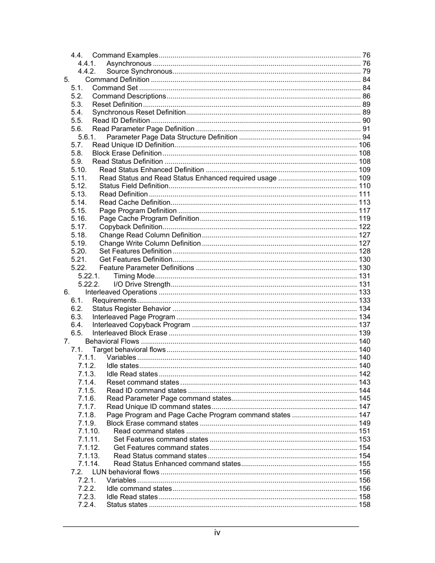
4.4. Command Examples....................................................................................................... 76
4.4.1. Asynchronous .......................................................................................................... 76
4.4.2. Source Synchronous................................................................................................ 79
Command Definition ........................................................................................................... 84
5.1. Command Set ................................................................................................................. 84
5.2. Command Descriptions................................................................................................... 86
5.3. Reset Definition............................................................................................................... 89
5.4. Synchronous Reset Definition......................................................................................... 89
5.5. Read ID Definition........................................................................................................... 90
5.6. Read Parameter Page Definition .................................................................................... 91
5.6.1. Parameter Page Data Structure Definition .............................................................. 94
5.7. Read Unique ID Definition............................................................................................. 106
5.8. Block Erase Definition................................................................................................... 108
5.9. Read Status Definition .................................................................................................. 108
Read Status Enhanced Definition ............................................................................. 109
5.10.
Read Status and Read Status Enhanced required usage ........................................ 109
5.11.
5.12.
Status Field Definition................................................................................................ 110
5.13.
Read Definition .......................................................................................................... 111
5.14.
Read Cache Definition............................................................................................... 113
Page Program Definition ........................................................................................... 117
5.15.
5.16.
Page Cache Program Definition................................................................................ 119
5.17.
Copyback Definition................................................................................................... 122
5.18.
Change Read Column Definition............................................................................... 127
5.19.
Change Write Column Definition ............................................................................... 127
Set Features Definition.............................................................................................. 128
5.20.
5.21. Get Features Definition.............................................................................................. 130
5.22.
Feature Parameter Definitions .................................................................................. 130
Timing Mode....................................................................................................... 131
I/O Drive Strength............................................................................................... 131
Interleaved Operations ..................................................................................................... 133
6.1. Requirements................................................................................................................ 133
6.2. Status Register Behavior .............................................................................................. 134
Interleaved Page Program ............................................................................................ 134
6.3.
6.4.
Interleaved Copyback Program .................................................................................... 137
6.5.
Interleaved Block Erase ................................................................................................ 139
Behavioral Flows .............................................................................................................. 140
7.1. Target behavioral flows................................................................................................. 140
7.1.1. Variables ................................................................................................................ 140
Idle states............................................................................................................... 140
7.1.2.
7.1.3.
Idle Read states..................................................................................................... 142
7.1.4. Reset command states .......................................................................................... 143
7.1.5. Read ID command states ...................................................................................... 144
7.1.6. Read Parameter Page command states................................................................ 145
7.1.7. Read Unique ID command states.......................................................................... 147
7.1.8. Page Program and Page Cache Program command states ................................. 147
7.1.9. Block Erase command states ................................................................................ 149
7.1.10.
Read command states ....................................................................................... 151
7.1.11.
Set Features command states ........................................................................... 153
7.1.12.
Get Features command states........................................................................... 154
Read Status command states ............................................................................ 154
7.1.13.
7.1.14.
Read Status Enhanced command states........................................................... 155
7.2. LUN behavioral flows .................................................................................................... 156
7.2.1. Variables ................................................................................................................ 156
7.2.2.
Idle command states.............................................................................................. 156
7.2.3.
Idle Read states..................................................................................................... 158
7.2.4. Status states .......................................................................................................... 158
5.22.1.
5.22.2.
6.
7.
iv
�
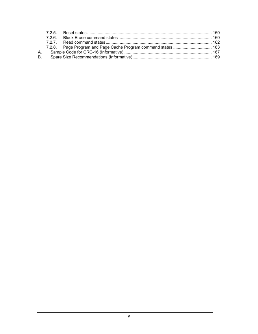
7.2.5. Reset states ........................................................................................................... 160
7.2.6. Block Erase command states ................................................................................ 160
7.2.7. Read command states........................................................................................... 162
7.2.8. Page Program and Page Cache Program command states ................................. 163
Sample Code for CRC-16 (Informative) ........................................................................... 167
Spare Size Recommendations (Informative).................................................................... 169
A.
B.
v
�
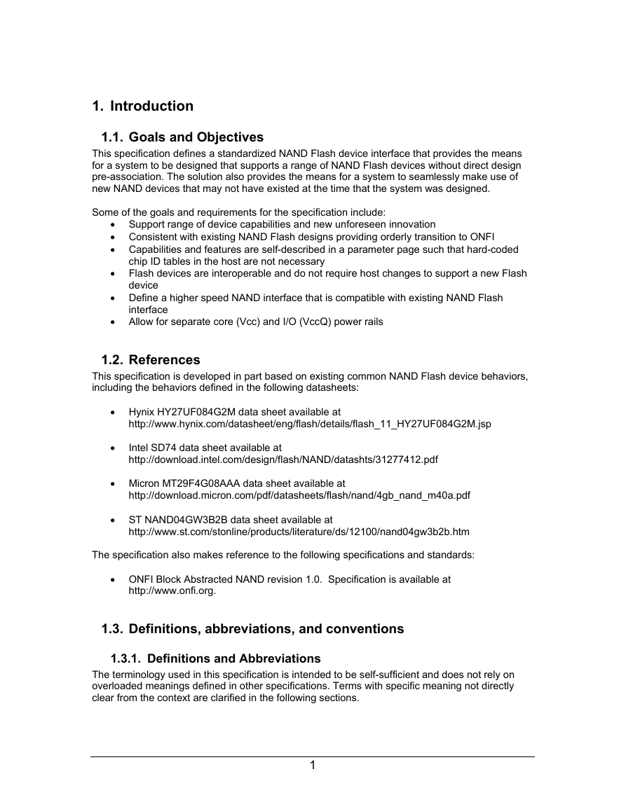
1. Introduction
1.1. Goals and Objectives
This specification defines a standardized NAND Flash device interface that provides the means
for a system to be designed that supports a range of NAND Flash devices without direct design
pre-association. The solution also provides the means for a system to seamlessly make use of
new NAND devices that may not have existed at the time that the system was designed.
Some of the goals and requirements for the specification include:
• Support range of device capabilities and new unforeseen innovation
• Consistent with existing NAND Flash designs providing orderly transition to ONFI
• Capabilities and features are self-described in a parameter page such that hard-coded
chip ID tables in the host are not necessary
• Flash devices are interoperable and do not require host changes to support a new Flash
• Define a higher speed NAND interface that is compatible with existing NAND Flash
device
interface
• Allow for separate core (Vcc) and I/O (VccQ) power rails
1.2. References
This specification is developed in part based on existing common NAND Flash device behaviors,
including the behaviors defined in the following datasheets:
• Hynix HY27UF084G2M data sheet available at
http://www.hynix.com/datasheet/eng/flash/details/flash_11_HY27UF084G2M.jsp
•
Intel SD74 data sheet available at
http://download.intel.com/design/flash/NAND/datashts/31277412.pdf
• Micron MT29F4G08AAA data sheet available at
http://download.micron.com/pdf/datasheets/flash/nand/4gb_nand_m40a.pdf
• ST NAND04GW3B2B data sheet available at
http://www.st.com/stonline/products/literature/ds/12100/nand04gw3b2b.htm
The specification also makes reference to the following specifications and standards:
• ONFI Block Abstracted NAND revision 1.0. Specification is available at
http://www.onfi.org.
1.3. Definitions, abbreviations, and conventions
1.3.1. Definitions and Abbreviations
The terminology used in this specification is intended to be self-sufficient and does not rely on
overloaded meanings defined in other specifications. Terms with specific meaning not directly
clear from the context are clarified in the following sections.
1
�
1.3.1.1. address
The address is comprised of a row address and a column address. The row address identifies
the page, block, and LUN to be accessed. The column address identifies the byte or word within
a page to access. The least significant bit of the column address shall always be zero in the
source synchronous data interface.
1.3.1.2. asynchronous
Asynchronous is when data is latched with the WE# signal for writes and RE# signal for reads.
1.3.1.3. block
Consists of multiple pages and is the smallest addressable unit for erase operations.
1.3.1.4. column
The byte (x8 devices) or word (x16 devices) location within the page register.
1.3.1.5. defect area
The defect area is where factory defects are marked by the manufacturer. Refer to section 3.2.
1.3.1.6. device
The packaged NAND unit. A device consists of one or more targets.
1.3.1.7. DDR
Acronym for double data rate.
1.3.1.8. Dword
A Dword is thirty-two (32) bits of data. A Dword may be represented as 32 bits, as two adjacent
words, or as four adjacent bytes. When shown as bits the least significant bit is bit 0 and most
significant bit is bit 31. The most significant bit is shown on the left. When shown as words the
least significant word (lower) is word 0 and the most significant (upper) word is word 1. When
shown as bytes the least significant byte is byte 0 and the most significant byte is byte 3. See
Figure 1 for a description of the relationship between bytes, words, and Dwords.
1.3.1.9. latching edge
The latching edge describes the edge of the CLK or the DQS signal that the contents of the data
bus are latched on for the source synchronous data interface. For data cycles the latching edge
is both the rising and falling edges of the DQS signal. For command and address cycles the
latching edge is the rising edge of the CLK signal.
1.3.1.10. LUN (logical unit number)
The minimum unit that can independently execute commands and report status. There are one
or more LUNs per target.
1.3.1.11. na
na stands for “not applicable”. Fields marked as “na” are not used.
2
�
1.3.1.12. O/M
O/M stands for Optional/Mandatory requirement. When the entry is set to “M”, the item is
mandatory. When the entry is set to “O”, the item is optional.
1.3.1.13. page
The smallest addressable unit for read and program operations. For targets that support partial
page programming, the smallest addressable unit for program operations is a partial page if there
are partial programming constraints.
1.3.1.14. page register
Register used to read data from that was transferred from the Flash array. For program
operations, the data is placed in this register prior to transferring the data to the Flash array.
1.3.1.15. partial page
The smallest unit that may be written in a program operation if there are partial programming
constraints (described in section 5.6.1.23).
1.3.1.16. read request
A read request is a data output cycle request from the host that results in a data transfer from the
device to the host. Refer to section 4.1.2 for information on data output cycles.
1.3.1.17. row
Refers to the block and page to be accessed.
1.3.1.18. source synchronous
Source synchronous is when the strobe (DQS) is forwarded with the data to indicate when the
data should be latched. The strobe signal, DQS, can be thought of as an additional data bus bit.
1.3.1.19. SR[ ]
SR refers to the status register contained within a particular LUN. SR[x] refers to bit x in the
status register for the associated LUN. Refer to section 5.12 for the definition of bit meanings
within the status register.
1.3.1.20. target
An independent Flash component with its own CE# signal.
1.3.1.21. word
A word is sixteen (16) bits of data. A word may be represented as 16 bits or as two adjacent
bytes. When shown as bits the least significant bit is bit 0 and most significant bit is bit 15. The
most significant bit is shown on the left. When shown as bytes the least significant byte (lower) is
byte 0 and the most significant byte (upper) is byte 1. See Figure 1 for a description of the
relationship between bytes, words and Dwords.
3
�




 2023年江西萍乡中考道德与法治真题及答案.doc
 2012年重庆南川中考生物真题及答案.doc
 2013年江西师范大学地理学综合及文艺理论基础考研真题.doc
 2020年四川甘孜小升初语文真题及答案I卷.doc
 2020年注册岩土工程师专业基础考试真题及答案.doc
 2023-2024学年福建省厦门市九年级上学期数学月考试题及答案.doc
 2021-2022学年辽宁省沈阳市大东区九年级上学期语文期末试题及答案.doc
 2022-2023学年北京东城区初三第一学期物理期末试卷及答案.doc
 2018上半年江西教师资格初中地理学科知识与教学能力真题及答案.doc
 2012年河北国家公务员申论考试真题及答案-省级.doc
 2020-2021学年江苏省扬州市江都区邵樊片九年级上学期数学第一次质量检测试题及答案.doc
 2022下半年黑龙江教师资格证中学综合素质真题及答案.doc