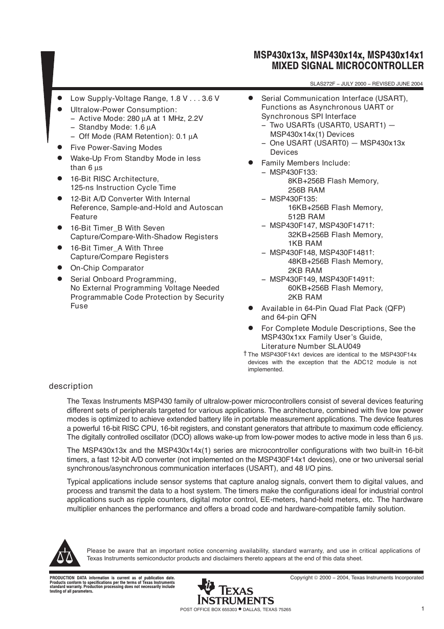
MSP430x13x, MSP430x14x, MSP430x14x1MIXED SIGNAL MICROCONTROLLERSLAS272F − JULY 2000 − REVISED JUNE 20041POST OFFICE BOX 655303 • DALLAS, TEXAS 75265DLow Supply-Voltage Range, 1.8 V...3.6 VDUltralow-Power Consumption:− Active Mode: 280 µA at 1 MHz, 2.2V− Standby Mode: 1.6 µA− Off Mode (RAM Retention): 0.1 µADFive Power-Saving ModesDWake-Up From Standby Mode in less than 6 µsD16-Bit RISC Architecture,125-ns Instruction Cycle TimeD12-Bit A/D Converter With InternalReference, Sample-and-Hold and AutoscanFeatureD16-Bit Timer_B With SevenCapture/Compare-With-Shadow RegistersD16-Bit Timer_A With ThreeCapture/Compare RegistersDOn-Chip ComparatorDSerial Onboard Programming,No External Programming Voltage NeededProgrammable Code Protection by SecurityFuseDSerial Communication Interface (USART),Functions as Asynchronous UART orSynchronous SPI Interface− Two USARTs (USART0, USART1) —MSP430x14x(1) Devices− One USART (USART0) — MSP430x13xDevicesDFamily Members Include:− MSP430F133:8KB+256B Flash Memory,256B RAM− MSP430F135:16KB+256B Flash Memory,512B RAM− MSP430F147, MSP430F1471†:32KB+256B Flash Memory,1KB RAM− MSP430F148, MSP430F1481†:48KB+256B Flash Memory,2KB RAM− MSP430F149, MSP430F1491†:60KB+256B Flash Memory,2KB RAMDAvailable in 64-Pin Quad Flat Pack (QFP)and 64-pin QFNDFor Complete Module Descriptions, See theMSP430x1xx Family User’s Guide,Literature Number SLAU049†The MSP430F14x1 devices are identical to the MSP430F14xdevices with the exception that the ADC12 module is notimplemented. descriptionThe Texas Instruments MSP430 family of ultralow-power microcontrollers consist of several devices featuringdifferent sets of peripherals targeted for various applications. The architecture, combined with five low powermodes is optimized to achieve extended battery life in portable measurement applications. The device featuresa powerful 16-bit RISC CPU, 16-bit registers, and constant generators that attribute to maximum code efficiency.The digitally controlled oscillator (DCO) allows wake-up from low-power modes to active mode in less than 6µs.The MSP430x13x and the MSP430x14x(1) series are microcontroller configurations with two built-in 16-bittimers, a fast 12-bit A/D converter (not implemented on the MSP430F14x1 devices), one or two universal serialsynchronous/asynchronous communication interfaces (USART), and 48 I/O pins.Typical applications include sensor systems that capture analog signals, convert them to digital values, andprocess and transmit the data to a host system. The timers make the configurations ideal for industrial controlapplications such as ripple counters, digital motor control, EE-meters, hand-held meters, etc. The hardwaremultiplier enhances the performance and offers a broad code and hardware-compatible family solution.Copyright 2000 − 2004, Texas Instruments IncorporatedPRODUCTION DATA information is current as of publication date.Products conform to specifications per the terms of Texas Instrumentsstandard warranty. Production processing does not necessarily includetesting of all parameters.Please be aware that an important notice concerning availability, standard warranty, and use in critical applications ofTexasInstruments semiconductor products and disclaimers thereto appears at the end of this data sheet.�
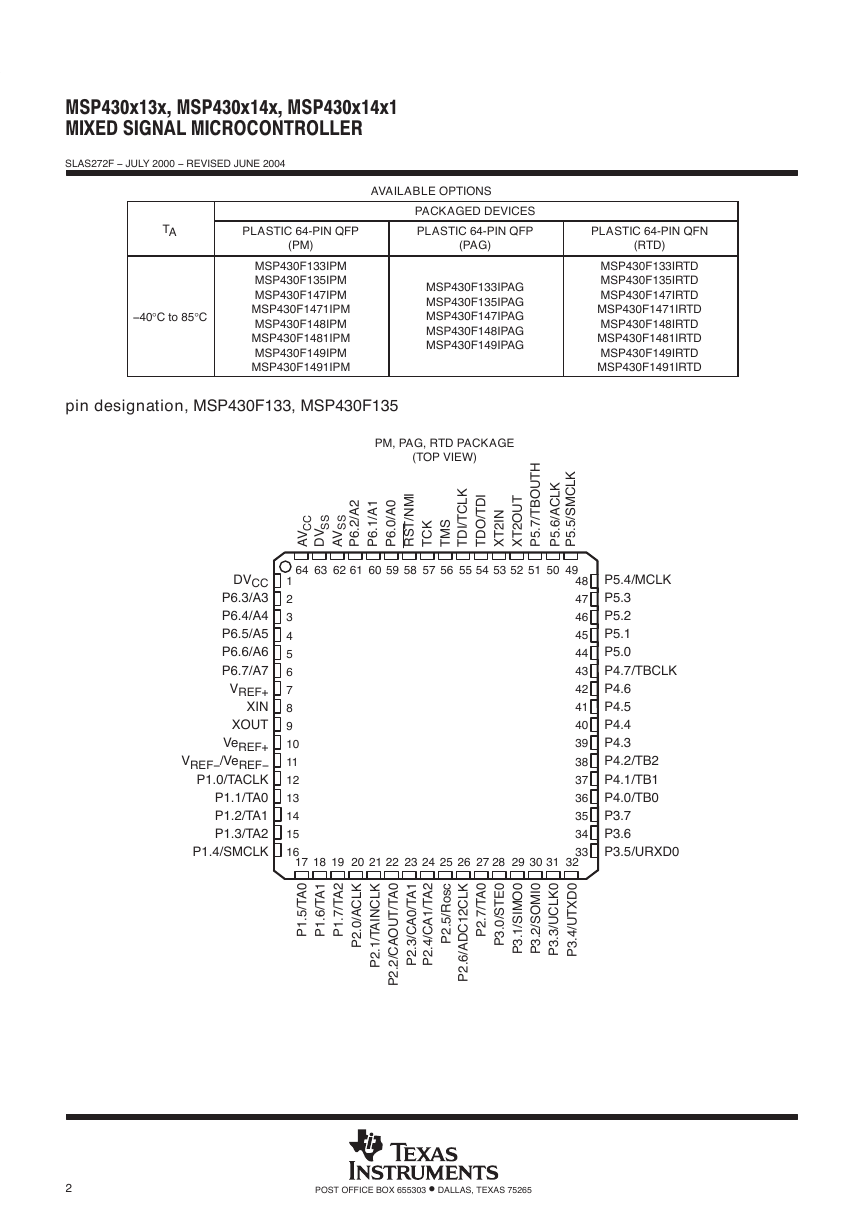
MSP430x13x, MSP430x14x, MSP430x14x1MIXED SIGNAL MICROCONTROLLERSLAS272F − JULY 2000 − REVISED JUNE 20042POST OFFICE BOX 655303 • DALLAS, TEXAS 75265AVAILABLE OPTIONSPACKAGED DEVICESTAPLASTIC 64-PIN QFP(PM)PLASTIC 64-PIN QFP(PAG)PLASTIC 64-PIN QFN(RTD)−40°C to 85°CMSP430F133IPMMSP430F135IPMMSP430F147IPMMSP430F1471IPMMSP430F148IPMMSP430F1481IPMMSP430F149IPMMSP430F1491IPMMSP430F133IPAGMSP430F135IPAGMSP430F147IPAGMSP430F148IPAGMSP430F149IPAGMSP430F133IRTDMSP430F135IRTDMSP430F147IRTDMSP430F1471IRTDMSP430F148IRTDMSP430F1481IRTDMSP430F149IRTDMSP430F1491IRTDpin designation, MSP430F133, MSP430F135171819P5.4/MCLKP5.3P5.2P5.1P5.0P4.7/TBCLKP4.6P4.5P4.4P4.3P4.2/TB2P4.1/TB1P4.0/TB0P3.7P3.6P3.5/URXD0484746454443424140393837363534332012345678910111213141516DVCCP6.3/A3P6.4/A4P6.5/A5P6.6/A6P6.7/A7VREF+XINXOUTVeREF+VREF−/VeREF−P1.0/TACLKP1.1/TA0P1.2/TA1P1.3/TA2P1.4/SMCLK21222324P5.6/ACLKTDO/TDI63626160596458AVP6.2/A2P6.1/A1P6.0/A0RST/NMITCKTMSP2.6/ADC12CLKP2.7/TA0P3.0/STE0P3.1/SIMO0P1.7/TA2P2.1/TAINCLKP2.2/CAOUT/TA0P2.3/CA0/TA1P2.4/CA1/TA2P2.5/Rosc5655545725262728295352P1.5/TA0XT2INXT2OUT515049303132P3.2/SOMI0P3.3/UCLK0P3.4/UTXD0P5.7/TBOUTHTDI/TCLKP5.5/SMCLKAVDVPM, PAG, RTD PACKAGE(TOP VIEW)P1.6/TA1P2.0/ACLKCCSSSS�
MSP430x13x, MSP430x14x, MSP430x14x1MIXED SIGNAL MICROCONTROLLERSLAS272F − JULY 2000 − REVISED JUNE 20043POST OFFICE BOX 655303 • DALLAS, TEXAS 75265pin designation, MSP430F147, MSP430F148, MSP430F149171819P5.4/MCLKP5.3/UCLK1P5.2/SOMI1P5.1/SIMO1P5.0/STE1P4.7/TBCLKP4.6/TB6P4.5/TB5P4.4/TB4P4.3/TB3P4.2/TB2P4.1/TB1P4.0/TB0P3.7/URXD1P3.6/UTXD1P3.5/URXD0484746454443424140393837363534332012345678910111213141516DVCCP6.3/A3P6.4/A4P6.5/A5P6.6/A6P6.7/A7VREF+XINXOUTVeREF+VREF−/VeREF−P1.0/TACLKP1.1/TA0P1.2/TA1P1.3/TA2P1.4/SMCLK21222324P5.6/ACLKTDO/TDI63626160596458AVP6.2/A2P6.1/A1P6.0/A0RST/NMITCKTMSP2.6/ADC12CLKP2.7/TA0P3.0/STE0P3.1/SIMO0P1.7/TA2P2.1/TAINCLKP2.2/CAOUT/TA0P2.3/CA0/TA1P2.4/CA1/TA2P2.5/Rosc5655545725262728295352P1.5/TA0XT2INXT2OUT515049303132P3.2/SOMI0P3.3/UCLK0P3.4/UTXD0P5.7/TBOUTHTDI/TCLKP5.5/SMCLKAVDVPM, PAG, RTD PACKAGE(TOP VIEW)P1.6/TA1P2.0/ACLKCCSSSS�
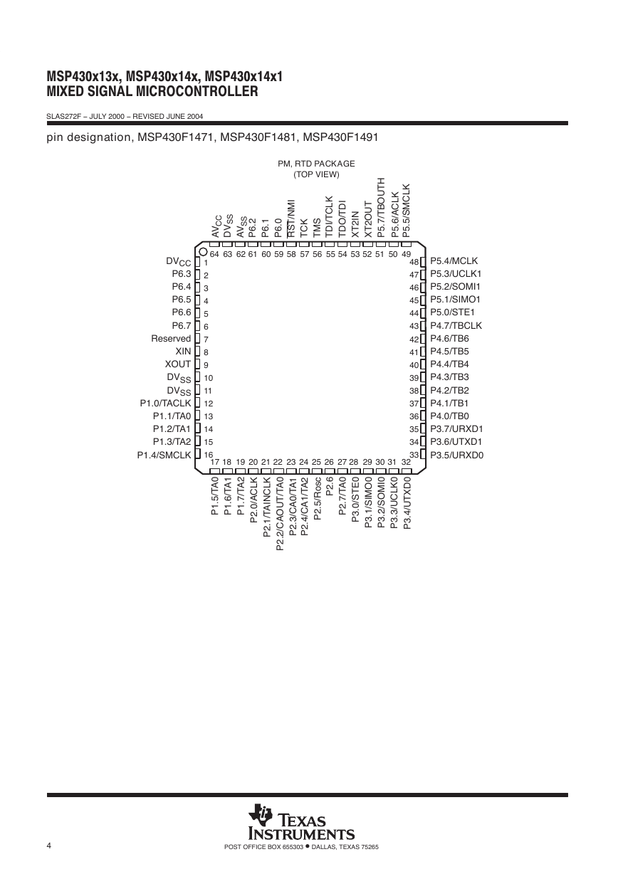
MSP430x13x, MSP430x14x, MSP430x14x1MIXED SIGNAL MICROCONTROLLERSLAS272F − JULY 2000 − REVISED JUNE 20044POST OFFICE BOX 655303 • DALLAS, TEXAS 75265pin designation, MSP430F1471, MSP430F1481, MSP430F1491171819P5.4/MCLKP5.3/UCLK1P5.2/SOMI1P5.1/SIMO1P5.0/STE1P4.7/TBCLKP4.6/TB6P4.5/TB5P4.4/TB4P4.3/TB3P4.2/TB2P4.1/TB1P4.0/TB0P3.7/URXD1P3.6/UTXD1P3.5/URXD0484746454443424140393837363534332012345678910111213141516DVCCP6.3P6.4P6.5P6.6P6.7ReservedXINXOUTDVSSDVSSP1.0/TACLKP1.1/TA0P1.2/TA1P1.3/TA2P1.4/SMCLK21222324P5.6/ACLKTDO/TDI63626160596458AVP6.2P6.1P6.0RST/NMITCKTMSP2.6P2.7/TA0P3.0/STE0P3.1/SIMO0P1.7/TA2P2.1/TAINCLKP2.2/CAOUT/TA0P2.3/CA0/TA1P2.4/CA1/TA2P2.5/Rosc5655545725262728295352P1.5/TA0XT2INXT2OUT515049303132P3.2/SOMI0P3.3/UCLK0P3.4/UTXD0P5.7/TBOUTHTDI/TCLKP5.5/SMCLKAVDVPM, RTD PACKAGE(TOP VIEW)P1.6/TA1P2.0/ACLKCCSSSS�
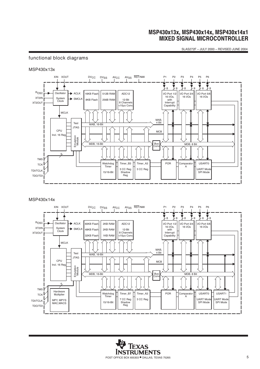
MSP430x13x, MSP430x14x, MSP430x14x1MIXED SIGNAL MICROCONTROLLERSLAS272F − JULY 2000 − REVISED JUNE 20045POST OFFICE BOX 655303 • DALLAS, TEXAS 75265functional block diagramsMSP430x13xOscillatorACLKSMCLKCPUIncl. 16 Reg.BusConvMCBXINXOUTP3P4P2XT2INXT2OUTTMSTCKMDB, 16 BitMAB, 16 BitMCLK4TDI/TCLKTDO/TDIP5P6MAB,4 BitDVCCDVSSAVCCAVSSRST/NMISystemClockROSCP116KB Flash8KB Flash512B RAM256B RAMADC1212-Bit8 Channels<10µs Conv.WatchdogTimer15/16-BitTimer_B33 CC RegShadowRegTimer_A33 CC RegTestJTAGEmulationModuleI/O Port 1/216 I/Os,withInterruptCapabilityI/O Port 3/416 I/OsPORComparatorAUSART0UART ModeSPI ModeI/O Port 5/616 I/OsMDB, 8 BitMDB, 16-BitMAB, 16-Bit888888MSP430x14xOscillatorACLKSMCLKCPUIncl. 16 Reg.BusConvMCBXINXOUTP3P4P2XT2INXT2OUTTMSTCKMDB, 16 BitMAB, 16 BitMCLK4TDI/TCLKTDO/TDIP5P6MAB,4 BitDVCCDVSSAVCCAVSSRST/NMISystemClockROSCP1HardwareMultiplierMPY, MPYSMAC,MACS60KB Flash48KB Flash32KB Flash2KB RAM2KB RAM1KB RAMADC1212-Bit8 Channels<10µs Conv.WatchdogTimer15/16-BitTimer_B77 CC RegShadowRegTimer_A33 CC RegTestJTAGEmulationModuleI/O Port 1/216 I/Os,withInterruptCapabilityI/O Port 3/416 I/OsPORComparatorAUSART0UART ModeSPI ModeUSART1UART ModeSPI ModeI/O Port 5/616 I/OsMDB, 8 BitMDB, 16-BitMAB, 16-Bit888888�
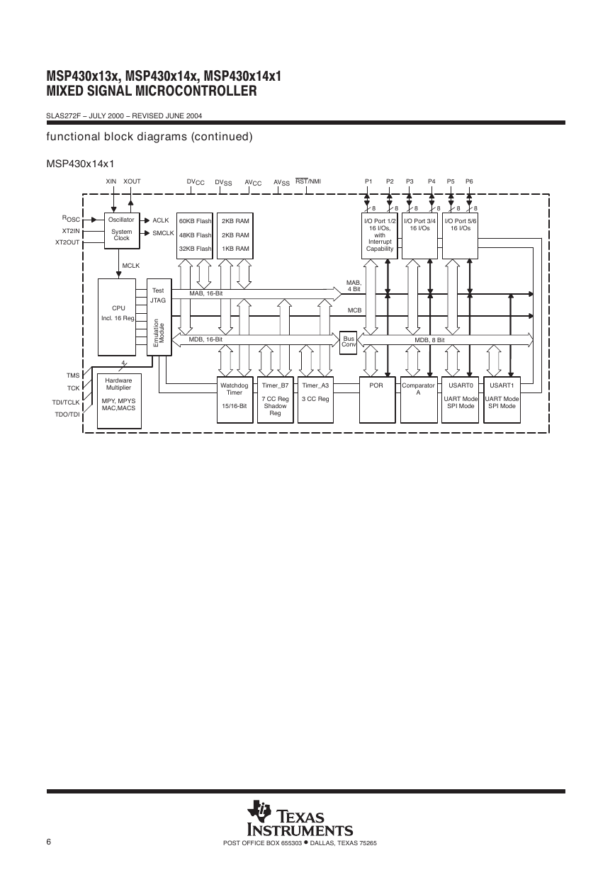
MSP430x13x, MSP430x14x, MSP430x14x1MIXED SIGNAL MICROCONTROLLERSLAS272F − JULY 2000 − REVISED JUNE 20046POST OFFICE BOX 655303 • DALLAS, TEXAS 75265functional block diagrams (continued)MSP430x14x1OscillatorACLKSMCLKCPUIncl. 16 Reg.BusConvMCBXINXOUTP3P4P2XT2INXT2OUTTMSTCKMDB, 16 BitMAB, 16 BitMCLK4TDI/TCLKTDO/TDIP5P6MAB,4 BitDVCCDVSSAVCCAVSSRST/NMISystemClockROSCP1HardwareMultiplierMPY, MPYSMAC,MACS60KB Flash48KB Flash32KB Flash2KB RAM2KB RAM1KB RAMWatchdogTimer15/16-BitTimer_B77 CC RegShadowRegTimer_A33 CC RegTestJTAGEmulationModuleI/O Port 1/216 I/Os,withInterruptCapabilityI/O Port 3/416 I/OsPORComparatorAUSART0UART ModeSPI ModeUSART1UART ModeSPI ModeI/O Port 5/616 I/OsMDB, 8 BitMDB, 16-BitMAB, 16-Bit888888�
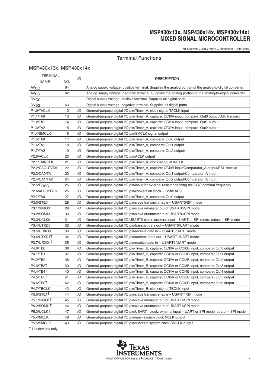
MSP430x13x, MSP430x14x, MSP430x14x1MIXED SIGNAL MICROCONTROLLERSLAS272F − JULY 2000 − REVISED JUNE 20047POST OFFICE BOX 655303 • DALLAS, TEXAS 75265Terminal FunctionsMSP430x13x, MSP430x14xTERMINALI/ODESCRIPTIONNAMENO.I/ODESCRIPTIONAVCC64Analog supply voltage, positive terminal. Supplies the analog portion of the analog-to-digital converter.AVSS62Analog supply voltage, negative terminal. Supplies the analog portion of the analog-to-digital converter.DVCC1Digital supply voltage, positive terminal. Supplies all digital parts.DVSS63Digital supply voltage, negative terminal. Supplies all digital parts.P1.0/TACLK12I/OGeneral-purpose digital I/O pin/Timer_A, clock signal TACLK inputP1.1/TA013I/OGeneral-purpose digital I/O pin/Timer_A, capture: CCI0A input, compare: Out0 output/BSL transmitP1.2/TA114I/OGeneral-purpose digital I/O pin/Timer_A, capture: CCI1A input, compare: Out1 outputP1.3/TA215I/OGeneral-purpose digital I/O pin/Timer_A, capture: CCI2A input, compare: Out2 outputP1.4/SMCLK16I/OGeneral-purpose digital I/O pin/SMCLK signal outputP1.5/TA017I/OGeneral-purpose digital I/O pin/Timer_A, compare: Out0 outputP1.6/TA118I/OGeneral-purpose digital I/O pin/Timer_A, compare: Out1 outputP1.7/TA219I/OGeneral-purpose digital I/O pin/Timer_A, compare: Out2 output/P2.0/ACLK20I/OGeneral-purpose digital I/O pin/ACLK outputP2.1/TAINCLK21I/OGeneral-purpose digital I/O pin/Timer_A, clock signal at INCLKP2.2/CAOUT/TA022I/OGeneral-purpose digital I/O pin/Timer_A, capture: CCI0B input/Comparator_A output/BSL receiveP2.3/CA0/TA123I/OGeneral-purpose digital I/O pin/Timer_A, compare: Out1 output/Comparator_A inputP2.4/CA1/TA224I/OGeneral-purpose digital I/O pin/Timer_A, compare: Out2 output/Comparator_A inputP2.5/ROSC25I/OGeneral-purpose digital I/O pin/input for external resistor defining the DCO nominal frequencyP2.6/ADC12CLK26I/OGeneral-purpose digital I/O pin/conversion clock – 12-bit ADCP2.7/TA027I/OGeneral-purpose digital I/O pin/Timer_A, compare: Out0 outputP3.0/STE028I/OGeneral-purpose digital I/O pin/slave transmit enable – USART0/SPI modeP3.1/SIMO029I/OGeneral-purpose digital I/O pin/slave in/master out of USART0/SPI modeP3.2/SOMI030I/OGeneral-purpose digital I/O pin/slave out/master in of USART0/SPI modeP3.3/UCLK031I/OGeneral-purpose digital I/O/USART0 clock: external input − UART or SPI mode, output – SPI modeP3.4/UTXD032I/OGeneral-purpose digital I/O pin/transmit data out – USART0/UART modeP3.5/URXD033I/OGeneral-purpose digital I/O pin/receive data in – USART0/UART modeP3.6/UTXD1†34I/OGeneral-purpose digital I/O pin/transmit data out – USART1/UART modeP3.7/URXD1†35I/OGeneral-purpose digital I/O pin/receive data in – USART1/UART modeP4.0/TB036I/OGeneral-purpose digital I/O pin/Timer_B, capture: CCI0A or CCI0B input, compare: Out0 outputP4.1/TB137I/OGeneral-purpose digital I/O pin/Timer_B, capture: CCI1A or CCI1B input, compare: Out1 outputP4.2/TB238I/OGeneral-purpose digital I/O pin/Timer_B, capture: CCI2A or CCI2B input, compare: Out2 outputP4.3/TB3†39I/OGeneral-purpose digital I/O pin/Timer_B, capture: CCI3A or CCI3B input, compare: Out3 outputP4.4/TB4†40I/OGeneral-purpose digital I/O pin/Timer_B, capture: CCI4A or CCI4B input, compare: Out4 outputP4.5/TB5†41I/OGeneral-purpose digital I/O pin/Timer_B, capture: CCI5A or CCI5B input, compare: Out5 outputP4.6/TB6†42I/OGeneral-purpose digital I/O pin/Timer_B, capture: CCI6A or CCI6B input, compare: Out6 outputP4.7/TBCLK43I/OGeneral-purpose digital I/O pin/Timer_B, clock signal TBCLK inputP5.0/STE1†44I/OGeneral-purpose digital I/O pin/slave transmit enable – USART1/SPI modeP5.1/SIMO1†45I/OGeneral-purpose digital I/O pin/slave in/master out of USART1/SPI modeP5.2/SOMI1†46I/OGeneral-purpose digital I/O pin/slave out/master in of USART1/SPI modeP5.3/UCLK1†47I/OGeneral-purpose digital I/O pin/USART1 clock: external input − UART or SPI mode, output – SPI modeP5.4/MCLK48I/OGeneral-purpose digital I/O pin/main system clock MCLK outputP5.5/SMCLK49I/OGeneral-purpose digital I/O pin/submain system clock SMCLK output†14x devices only�
MSP430x13x, MSP430x14x, MSP430x14x1MIXED SIGNAL MICROCONTROLLERSLAS272F − JULY 2000 − REVISED JUNE 20048POST OFFICE BOX 655303 • DALLAS, TEXAS 75265Terminal Functions (Continued)MSP430x13x, MSP430x14x (continued)TERMINALI/ODESCRIPTIONNAMENO.I/ODESCRIPTIONP5.6/ACLK50I/OGeneral-purpose digital I/O pin/auxiliary clock ACLK outputP5.7/TBOUTH51I/OGeneral-purpose digital I/O pin/switch all PWM digital output ports to high impedance − Timer_B7: TB0 toTB6P6.0/A059I/OGeneral-purpose digital I/O pin/analog input a0 – 12-bit ADCP6.1/A160I/OGeneral-purpose digital I/O pin/analog input a1 – 12-bit ADCP6.2/A261I/OGeneral-purpose digital I/O pin/analog input a2 – 12-bit ADCP6.3/A32I/OGeneral-purpose digital I/O pin/analog input a3 – 12-bit ADCP6.4/A43I/OGeneral-purpose digital I/O pin/analog input a4 – 12-bit ADCP6.5/A54I/OGeneral-purpose digital I/O pin/analog input a5 – 12-bit ADCP6.6/A65I/OGeneral-purpose digital I/O pin/analog input a6 – 12-bit ADCP6.7/A76I/OGeneral-purpose digital I/O pin/analog input a7 – 12-bit ADCRST/NMI58IReset input, nonmaskable interrupt input port, or bootstrap loader start (in Flash devices).TCK57ITest clock. TCK is the clock input port for device programming test and bootstrap loader start (in Flashdevices).TDI/TCLK55ITest data input or test clock input. The device protection fuse is connected to TDI/TCLK.TDO/TDI54I/OTest data output port. TDO/TDI data output or programming data input terminalTMS56ITest mode select. TMS is used as an input port for device programming and test.VeREF+10IInput for an external reference voltage to the ADCVREF+7OOutput of positive terminal of the reference voltage in the ADCVREF−/VeREF−11INegative terminal for the ADC’s reference voltage for both sources, the internal reference voltage, or anexternal applied reference voltageXIN8IInput port for crystal oscillator XT1. Standard or watch crystals can be connected.XOUT9OOutput terminal of crystal oscillator XT1XT2IN53IInput port for crystal oscillator XT2. Only standard crystals can be connected.XT2OUT52OOutput terminal of crystal oscillator XT2QFN PadNANAQFN package pad connection to DVSS recommended.�



 2023年江西萍乡中考道德与法治真题及答案.doc
 2012年重庆南川中考生物真题及答案.doc
 2013年江西师范大学地理学综合及文艺理论基础考研真题.doc
 2020年四川甘孜小升初语文真题及答案I卷.doc
 2020年注册岩土工程师专业基础考试真题及答案.doc
 2023-2024学年福建省厦门市九年级上学期数学月考试题及答案.doc
 2021-2022学年辽宁省沈阳市大东区九年级上学期语文期末试题及答案.doc
 2022-2023学年北京东城区初三第一学期物理期末试卷及答案.doc
 2018上半年江西教师资格初中地理学科知识与教学能力真题及答案.doc
 2012年河北国家公务员申论考试真题及答案-省级.doc
 2020-2021学年江苏省扬州市江都区邵樊片九年级上学期数学第一次质量检测试题及答案.doc
 2022下半年黑龙江教师资格证中学综合素质真题及答案.doc