VTI
科技 SCA100T 丛书
SCA100T 双重的轴倾角罗盘系列 THE SCA100T DUAL AXIS INCLINOMETER SERIES
The SCA100T Series is a 3D-MEMS-based dual axis inclinometer family that provides instrumentation grade performance for leveling
applications. The measuring axes of the sensing elements are parallel to the mounting plane and orthogonal to each other. Low temperature
dependency, high resolution and low noise, together a with robust sensing element design, make the SCA100T the ideal choice for leveling
instruments. The VTI inclinometers are insensitive to vibration, due to their over damped sensing elements, and can withstand mechanical
shocks of up to 20000 g.
特征 Features
• Dual axis inclination measurement (X and Y)
• Measuring ranges ±30° SCA100T-D01 and±
90° SCA100T-D02
• 0.0025° resolution (10 Hz BW, 模拟输出)
• Sensing element controlled over damped
frequency response (-3dB 18Hz)
• Robust design, high shock durability (20000g)
• High stability over temperature and time
• Single +5 V supply
• Ratiometric analog voltage outputs
应用Applications
• SPI角度和温度输出Digital SPI inclination and temperature output
• 多种失败检测功能Comprehensive failure detection features
o True self test by deflecting the sensing
elements’ proof mass by electrostatic
force.
o Continuous sensing element interconnection
failure check.
o Continuous memory parity check.
• RoHS compliant
• Compatible with Pb-free reflow solder process
•平台调平和稳定Platform leveling and stabilization
• 360°垂直定向测量360° vertical orientation measurement
• 仪器调平Leveling instruments
•构造层次Construction levels
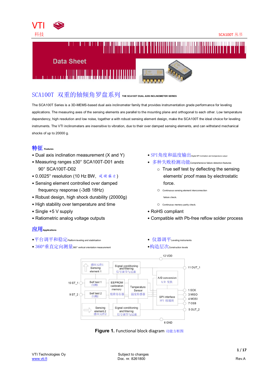
Figure 1. Functional block diagram 功能方框图
1 / 17
VTI Technologies Oy Subject to changes
www.vti.fi Doc. nr. 8261800 Rev.A
�
VTI
1. 电器特性 Electrical Specifications
科技 SCA100T 丛书
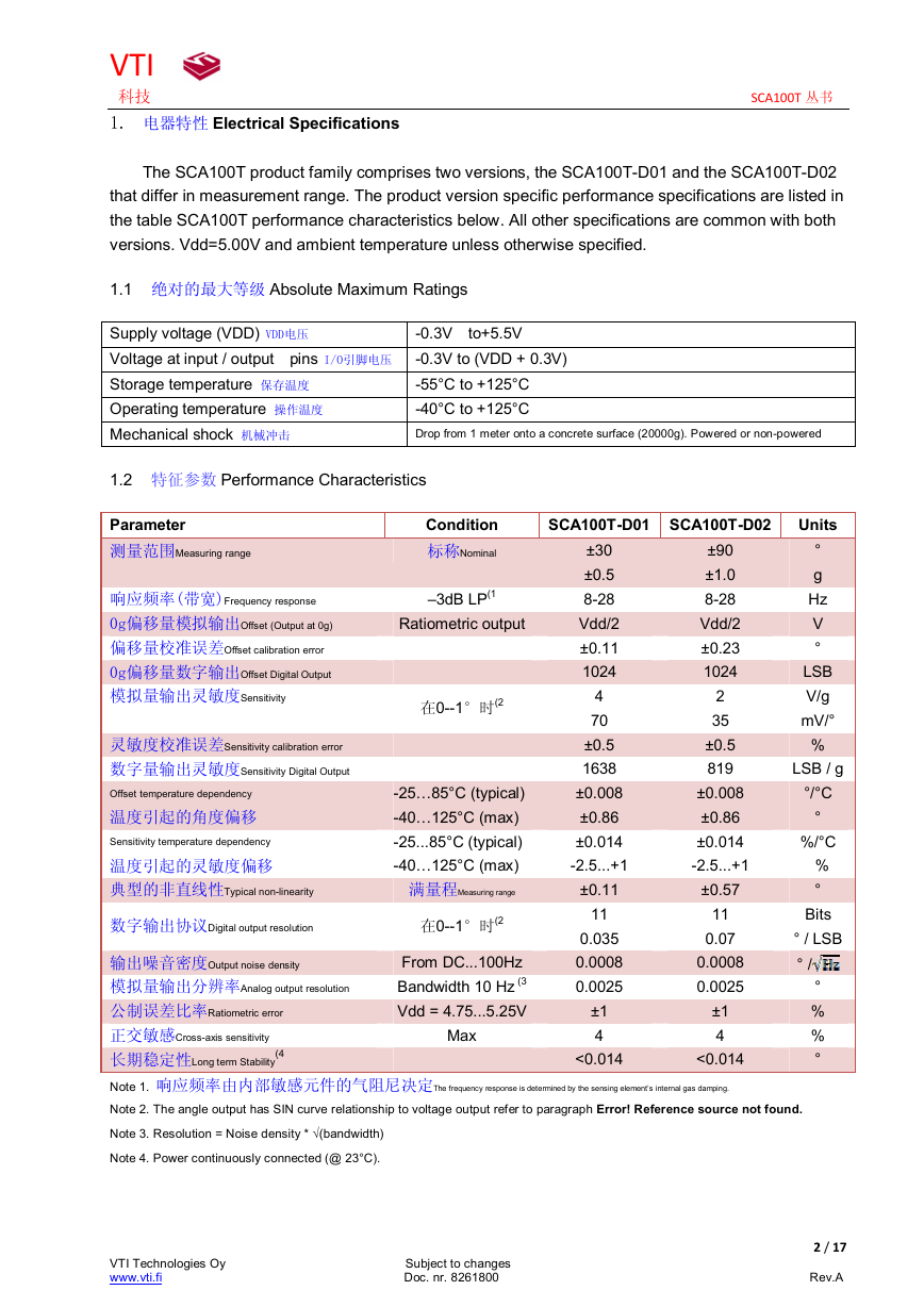
The SCA100T product family comprises two versions, the SCA100T-D01 and the SCA100T-D02
that differ in measurement range. The product version specific performance specifications are listed in
the table SCA100T performance characteristics below. All other specifications are common with both
versions. Vdd=5.00V and ambient temperature unless otherwise specified.
1.1 绝对的最大等级 Absolute Maximum Ratings
Supply voltage (VDD) VDD电压
Voltage at input / output pins I/O引脚电压 -0.3V to (VDD + 0.3V)
Storage temperature 保存温度
Operating temperature 操作温度
Mechanical shock 机械冲击
-0.3V to+5.5V
-55°C to +125°C
-40°C to +125°C
Drop from 1 meter onto a concrete surface (20000g). Powered or non-powered
1.2 特征参数 Performance Characteristics
Parameter
测量范围Measuring range
响应频率(带宽)Frequency response
0g偏移量模拟输出Offset (Output at 0g)
偏移量校准误差Offset calibration error
0g偏移量数字输出Offset Digital Output
模拟量输出灵敏度Sensitivity
Condition
标称Nominal
–3dB LP(1
Ratiometric output
在0--1°时(2
灵敏度校准误差Sensitivity calibration error
数字量输出灵敏度Sensitivity Digital Output
Offset temperature dependency
温度引起的角度偏移
Sensitivity temperature dependency
温度引起的灵敏度偏移
典型的非直线性Typical non-linearity
数字输出协议Digital output resolution
输出噪音密度Output noise density
模拟量输出分辨率Analog output resolution
公制误差比率Ratiometric error
正交敏感Cross-axis sensitivity
长期稳定性Long term Stability
(4
-25…85°C (typical)
-40…125°C (max)
-25...85°C (typical)
-40…125°C (max)
满量程Measuring range
在0--1°时(2
From DC...100Hz
Bandwidth 10 Hz (3
Vdd = 4.75...5.25V
Max
SCA100T-D01 SCA100T-D02
Units
±30
±0.5
8-28
Vdd/2
±0.11
1024
4
70
±0.5
1638
±0.008
±0.86
±0.014
-2.5...+1
±0.11
11
0.035
0.0008
0.0025
±1
4
<0.014
±90
±1.0
8-28
Vdd/2
±0.23
1024
2
35
±0.5
819
±0.008
±0.86
±0.014
-2.5...+1
±0.57
11
0.07
0.0008
0.0025
±1
4
<0.014
°
g
Hz
V
°
LSB
V/g
mV/°
%
LSB / g
°/°C
°
%/°C
%
°
Bits
° / LSB
° /
°
%
%
°
Note 1. 响应频率由内部敏感元件的气阻尼决定The frequency response is determined by the sensing element’s internal gas damping.
Note 2. The angle output has SIN curve relationship to voltage output refer to paragraph Error! Reference source not found.
Note 3. Resolution = Noise density * √(bandwidth)
Note 4. Power continuously connected (@ 23°C).
2 / 17
VTI Technologies Oy Subject to changes
www.vti.fi Doc. nr. 8261800 Rev.A
�
VTI
科技 SCA100T 丛书
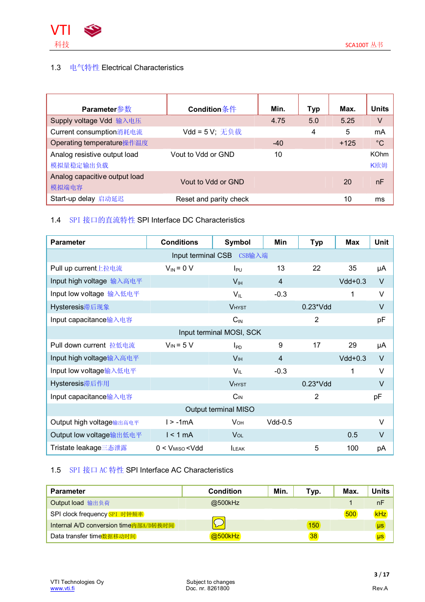
1.3 电气特性 Electrical Characteristics
Parameter参数
Condition条件
Supply voltage Vdd 输入电压
Current consumption消耗电流
Operating temperature操作温度
Analog resistive output load
模拟量稳定输出负载
Analog capacitive output load
模拟端电容
Start-up delay 启动延迟
Vdd = 5 V; 无负载
Vout to Vdd or GND
Vout to Vdd or GND
Reset and parity check
Min.
4.75
-40
10
Typ
5.0
4
Max.
5.25
5
+125
20
10
Units
V
mA
°C
KOhm
K欧姆
nF
ms
1.4 SPI 接口的直流特性 SPI Interface DC Characteristics
Parameter
Conditions
Symbol
Min
Typ
Max
Unit
Input terminal CSB CSB输入端
Pull up current上拉电流
Input high voltage 输入高电平
Input low voltage 输入低电平
Hysteresis滞后现象
Input capacitance输入电容
VIN = 0 V
IPU
VIH
VIL
VHYST
CIN
Input terminal MOSI, SCK
Pull down current 拉低电流
Input high voltage输入高电平
Input low voltage输入低电平
Hysteresis滞后作用
Input capacitance输入电容
VIN = 5 V
IPD
VIH
VIL
VHYST
CIN
Output terminal MISO
13
4
-0.3
9
4
-0.3
Output high voltage输出高电平
Output low voltage输出低电平
Tristate leakage三态泄露
I > -1mA
I < 1 mA
0 < VMISO
VTI
科技 SCA100T 丛书
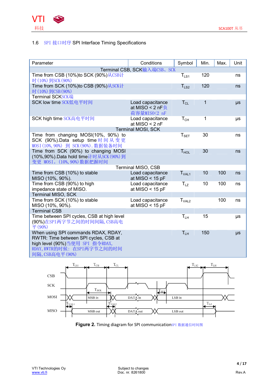
1.6 SPI 接口时序 SPI Interface Timing Specifications
Parameter
Conditions
Symbol Min. Max. Unit
Terminal CSB, SCK输入端CSB、SCK
Load capacitance
at MISO < 2 nF负
荷容量MISO<2 nF
Load capacitance
at MISO < 2 nF
Terminal MOSI, SCK
Terminal MISO, CSB
Load capacitance
at MISO < 15 pF
Load capacitance
at MISO < 15 pF
Load capacitance
at MISO < 15 pF
Time from CSB (10%)to SCK (90%)从CSB计
时(10%)到SCK(90%)
Time from SCK (10%)to CSB (90%)从SCK计
时(10%)到CSB(90%)
Terminal SCKSCK端
SCK low time SCK低电平时间
SCK high time SCK高电平时间
Time from changing MOSI(10%, 90%) to
SCK (90%).Data setup time 时 间 从 变 更
MOSI(10%,90%) 到 SCK(90%).数据装备时间
Time from SCK (90%) to changing MOSI
(10%,90%).Data hold time计时从SCK(90%)到
变更 MOSI。(10%,90%)数据把握时间
Time from CSB (10%) to stable
MISO (10%, 90%).
Time from CSB (90%) to high
impedance state of MISO.
Terminal MISO, SCK
Time from SCK (10%) to stable
MISO (10%, 90%).
Terminal CSB
Time between SPI cycles, CSB at high level
(90%)在SPI两字节之间的时间间隔,CSB高电
平(90%)
When using SPI commands RDAX, RDAY,
RWTR: Time between SPI cycles, CSB at
high level (90%)当使用 SPI 指令RDAX,
RDAY,RWTR的时候: 在SPI两字节之间的时间
间隔,CSB高电平(90%)
TLS1
TLS2
TCL
TCH
TSET
THOL
TVAL1
TLZ
TVAL2
TLH
120
120
1
1
30
30
10
10
15
TLH
150
100
100
100
ns
ns
µs
µs
ns
ns
ns
ns
ns
µs
µs
Figure 2. Timing diagram for SPI communicationSPI 数据通信时间图
4 / 17
VTI Technologies Oy Subject to changes
www.vti.fi Doc. nr. 8261800 Rev.A
�
VTI
科技 SCA100T 丛书
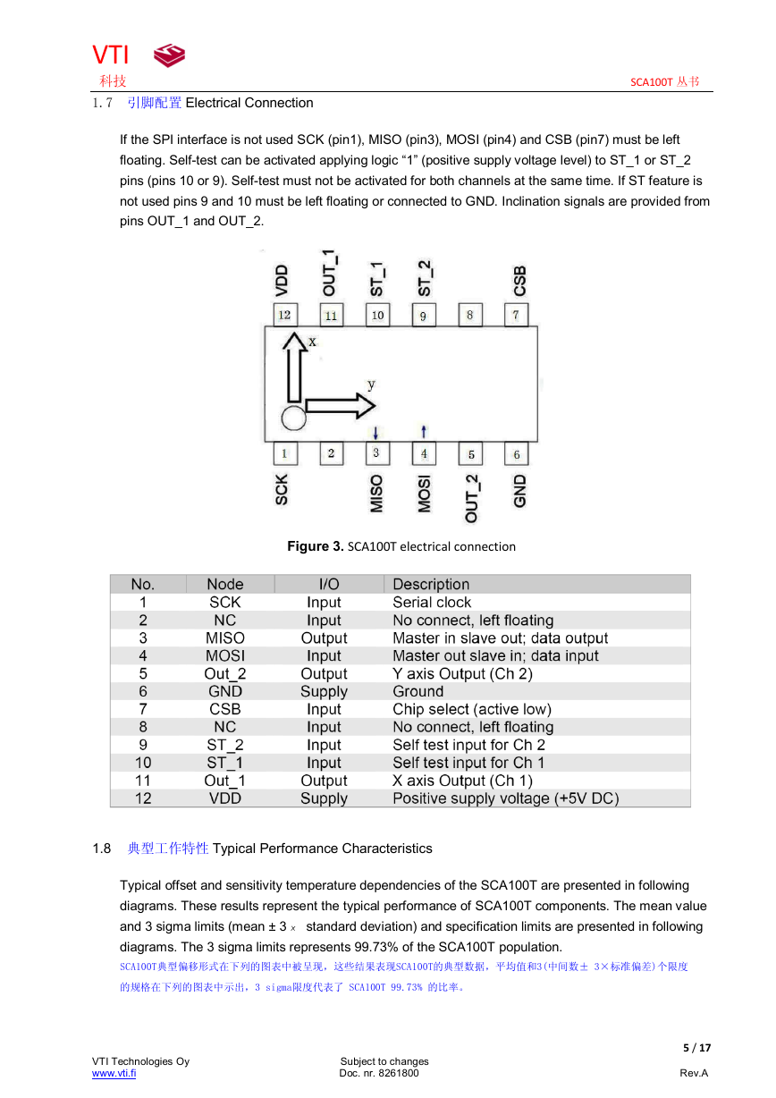
1.7 引脚配置 Electrical Connection
If the SPI interface is not used SCK (pin1), MISO (pin3), MOSI (pin4) and CSB (pin7) must be left
floating. Self-test can be activated applying logic “1” (positive supply voltage level) to ST_1 or ST_2
pins (pins 10 or 9). Self-test must not be activated for both channels at the same time. If ST feature is
not used pins 9 and 10 must be left floating or connected to GND. Inclination signals are provided from
pins OUT_1 and OUT_2.
Figure 3. SCA100T electrical connection
1.8 典型工作特性 Typical Performance Characteristics
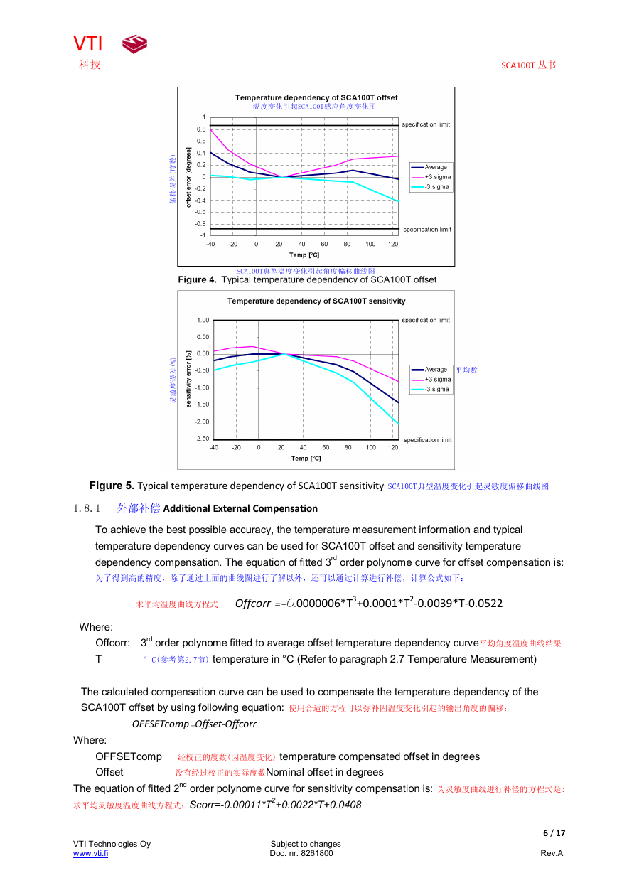
Typical offset and sensitivity temperature dependencies of the SCA100T are presented in following
diagrams. These results represent the typical performance of SCA100T components. The mean value
and 3 sigma limits (mean ± 3× standard deviation) and specification limits are presented in following
diagrams. The 3 sigma limits represents 99.73% of the SCA100T population.
SCA100T典型偏移形式在下列的图表中被呈现,这些结果表现SCA100T的典型数据,平均值和3(中间数± 3×标准偏差)个限度
的规格在下列的图表中示出,3 sigma限度代表了 SCA100T 99.73% 的比率。
5 / 17
VTI Technologies Oy Subject to changes
www.vti.fi Doc. nr. 8261800 Rev.A
�
VTI
科技 SCA100T 丛书
Figure 5. Typical temperature dependency of SCA100T sensitivity SCA100T典型温度变化引起灵敏度偏移曲线图
1.8.1 外部补偿 Additional External Compensation
To achieve the best possible accuracy, the temperature measurement information and typical
temperature dependency curves can be used for SCA100T offset and sensitivity temperature
dependency compensation. The equation of fitted 3rd order polynome curve for offset compensation is:
为了得到高的精度,除了通过上面的曲线图进行了解以外,还可以通过计算进行补偿,计算公式如下:
求平均温度曲线方程式 Offcorr =-0.0000006*T3+0.0001*T2-0.0039*T-0.0522
Where:
Offcorr: 3rd order polynome fitted to average offset temperature dependency curve平均角度温度曲线结果
T °C(参考第2.7节) temperature in °C (Refer to paragraph 2.7 Temperature Measurement)
The calculated compensation curve can be used to compensate the temperature dependency of the
SCA100T offset by using following equation: 使用合适的方程可以弥补因温度变化引起的输出角度的偏移:
OFFSETcomp=Offset-Offcorr
Where:
OFFSETcomp 经校正的度数(因温度变化) temperature compensated offset in degrees
Offset 没有经过校正的实际度数Nominal offset in degrees
The equation of fitted 2nd order polynome curve for sensitivity compensation is: 为灵敏度曲线进行补偿的方程式是:
求平均灵敏度温度曲线方程式:Scorr=-0.00011*T2+0.0022*T+0.0408
6 / 17
VTI Technologies Oy Subject to changes
www.vti.fi Doc. nr. 8261800 Rev.A
�
VTI
科技 SCA100T 丛书
Where:
Scorr: 平均灵敏度温度曲线结果2nd order polynome fitted to average sensitivity temperature dependency curve
T temperature in °C
The calculated compensation curve can be used to compensate the temperature dependency of
the SCA100T sensitivity by using following equation: 使用合适的方程可以弥补因温度变化引起的灵敏度偏移:
SENScomp=SENS*(1+Scorr/100)
Where:
SENScomp 经校正的灵敏度(因温度变化)temperature compensated sensitivity
SENS 没有经过校正的灵敏度Nominal sensitivity (4V/g SCA100T-D01, 2V/g SCA100T-D02)
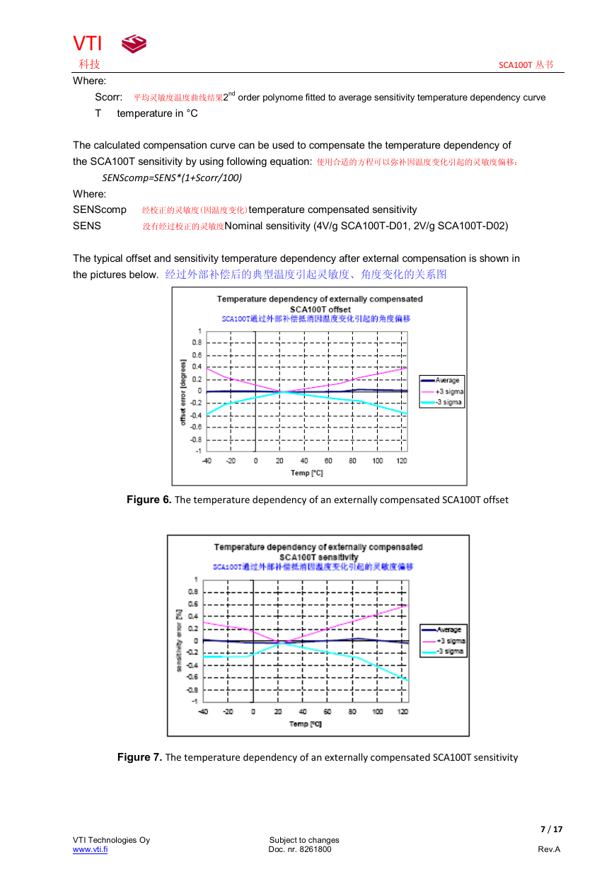
The typical offset and sensitivity temperature dependency after external compensation is shown in
the pictures below. 经过外部补偿后的典型温度引起灵敏度、角度变化的关系图
Figure 6. The temperature dependency of an externally compensated SCA100T offset
Figure 7. The temperature dependency of an externally compensated SCA100T sensitivity
7 / 17
VTI Technologies Oy Subject to changes
www.vti.fi Doc. nr. 8261800 Rev.A
�
VTI
科技 SCA100T 丛书
2. 功能描述 Functional Description
2.1 测量方向 Measuring Directions
VOUT > VOUT =2.5V > VOUT
Figure 8. The measuring directions of the SCA100TSCA100T 的测定方向
2.2 电压到角度转换 Voltage to Angle Conversion
Analog output can be transferred to angle using the following equation for conversion: 把输出的模拟量
转换为角度的方程式是:
α= arcsin [(Vout-offset)/Sensitivity]
公式中:offset是在0°输出的电压值(电压2.5v),Sensitivity是芯片灵敏度(SCA100T-D01是4v) Vout是芯
片输出的模拟量where: Offset = output of the device at 0° inclination position, Sensitivity is the sensitivity of the device and VDout is the output of the
SCA100T. The nominal offset is 2.5 V and the sensitivity is 4 V/g for the SCA100T-D01 and 2 V/g for the SCA100T-D02。
角度接近于0°时,可用以下简化方程式计算,计算结果的准确性可通过下表了解。Angles close to 0° inclination can
be estimated quite accurately with straight line conversion but for the best possible accuracy, arcsine conversion is recommended to be used. The following table
shows the angle measurement error if straight line conversion is used.
Straight line conversion equation: 简化转换方程式:
α=(Vout-offset)/Sensitivity (单位:度) Offset:0°输出电压2.5v
公式中:Sensitivity = 70mV/° (SCA100T-D01)或Sensitivity = 35mV/° (SCA100T-D01)Where: Sensitivity = 70mV/° with
SCA100T-D01 or Sensitivity= 35mV/° with SCA100T-D02
使用简化公式计算结果与实际倾斜角度之间的误差:
Tilt angle [°] 实际倾斜角度
0
1
2
3
4
5
10
15
30
Straight line conversion error [°] 使用简化方程计算引起的误差
0
0.0027
0.0058
0.0094
0.0140
0.0198
0.0787
0.2185
1.668
2.3 公制的输出比率 Ratiometric Output
Ratiometric output means that the zero offset point and sensitivity of the sensor are proportional to the supply
voltage. If the SCA100T supply voltage is fluctuating the SCA100T output will also vary.When the same
8 / 17
VTI Technologies Oy Subject to changes
www.vti.fi Doc. nr. 8261800 Rev.A
�


 2023年江西萍乡中考道德与法治真题及答案.doc
 2012年重庆南川中考生物真题及答案.doc
 2013年江西师范大学地理学综合及文艺理论基础考研真题.doc
 2020年四川甘孜小升初语文真题及答案I卷.doc
 2020年注册岩土工程师专业基础考试真题及答案.doc
 2023-2024学年福建省厦门市九年级上学期数学月考试题及答案.doc
 2021-2022学年辽宁省沈阳市大东区九年级上学期语文期末试题及答案.doc
 2022-2023学年北京东城区初三第一学期物理期末试卷及答案.doc
 2018上半年江西教师资格初中地理学科知识与教学能力真题及答案.doc
 2012年河北国家公务员申论考试真题及答案-省级.doc
 2020-2021学年江苏省扬州市江都区邵樊片九年级上学期数学第一次质量检测试题及答案.doc
 2022下半年黑龙江教师资格证中学综合素质真题及答案.doc