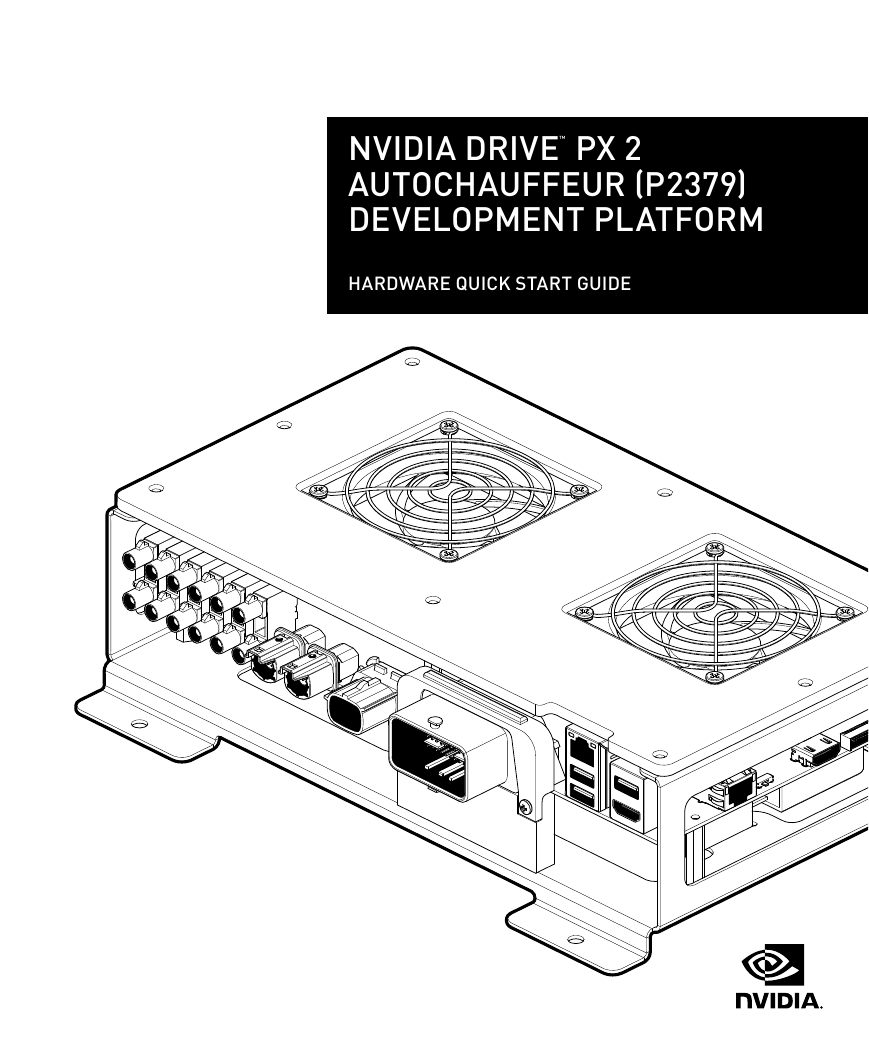
NVIDIA DRIVE™ PX 2
AUTOCHAUFFEUR (P2379)
DEVELOPMENT PLATFORM
HARDWARE QUICK START GUIDE
�
�
INTRODUCTION
Before You Begin
This document provides the basic steps needed to get your NVIDIA DRIVE™ PX 2 AutoChauffeur (P2379) Development Platform (SKU
2124) up and running. Please refer to the DRIVE developer documentation on DevZone for additional information on developing for
DRIVE PX 2.
DRIVE PX 2 (P2379) comes pre-installed with NVIDIA DRIVE software. At the end of this guide, NVIDIA DRIVE PX 2 (P2379) will open a
Linux desktop, from where you can run through various demonstrations.
Please refer to the DevZone located at https://developer.nvidia.com/driveworks for more information and resources.
HARDWARE
Table 1. NVIDIA DRIVE PX 2 Kit – Included Hardware
Item
1
2
3
4
5
6
7
8
Description
DRIVE PX 2 AutoChauffeur Development Platform (SKU 2124)
AC Power Supply with 10-pin Connector and US Power Cord
Vehicle Cable Harness
USB 3.0 Hub with Power Supply and USB 3.0 Cable
USB 2.0 Type A to Type A Cable for connecting to your Linux Host PC
Peripheral Adapter Board (PAB, P2779-100) and 30-Pin Cable
BroadR-Reach and GPIO Harness
Sekonix 2MP RCCB AR0231 60° FOV GMSL Camera and Fakra Coax Cable
Table 2. Additional Hardware Required to Complete this Hardware Quick Start Guide
(Duplicate set needed to work with Tegra B’s Linux Desktop)
Item
1
2
3
Description
HDMI Display with HDMI cable
Keyboard
Mouse
Table 3. Additional Hardware That Is Required for Development
Item
1
2
Description
Linux Host PC for Cross-Compiling, Flashing, and Console Access
Ethernet Cable for Internet Access
Page 1 | DRIVE PX 2 AutoChauffeur (P2379)
�
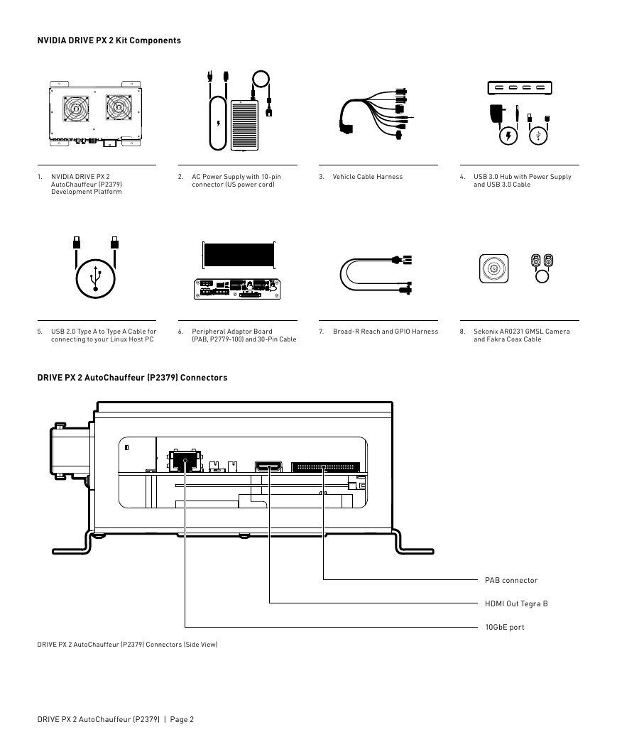
NVIDIA DRIVE PX 2 Kit Components
1. NVIDIA DRIVE PX 2
AutoChauffeur (P2379)
Development Platform
2. AC Power Supply with 10-pin
connector (US power cord)
3. Vehicle Cable Harness
4. USB 3.0 Hub with Power Supply
and USB 3.0 Cable
366159_DRIVE_PX2_Autochauffeur_Connector & Camera
5. USB 2.0 Type A to Type A Cable for
connecting to your Linux Host PC
6. Peripheral Adaptor Board
(PAB, P2779-100) and 30-Pin Cable
7. Broad-R Reach and GPIO Harness
8. Sekonix AR0231 GMSL Camera
and Fakra Coax Cable
DRIVE PX 2 AutoChauffeur (P2379) Connectors
PAB connector
HDMI Out Tegra B
10GbE port
DRIVE PX 2 AutoChauffeur (P2379) Connectors (Side View)
DRIVE PX 2 AutoChauffeur (P2379) | Page 2
�
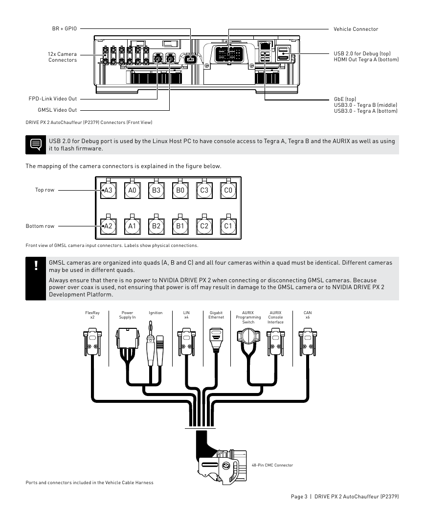
BR + GPIO
12x Camera
Connectors
FPD-Link Video Out
GMSL Video Out
DRIVE PX 2 AutoChauffeur (P2379) Connectors (Front View)
Vehicle Connector
USB 2.0 for Debug (top)
HDMI Out Tegra A (bottom)
GbE (top)
USB3.0 - Tegra B (middle)
USB3.0 - Tegra A (bottom)
USB 2.0 for Debug port is used by the Linux Host PC to have console access to Tegra A, Tegra B and the AURIX as well as using
it to flash firmware.
The mapping of the camera connectors is explained in the figure below.
Top row
A3
A0
B3
B0
C3
C0
Bottom row
A2
A1
B2
B1
C2
C1
Front view of GMSL camera input connectors. Labels show physical connections.
!
GMSL cameras are organized into quads (A, B and C) and all four cameras within a quad must be identical. Different cameras
may be used in different quads.
Always ensure that there is no power to NVIDIA DRIVE PX 2 when connecting or disconnecting GMSL cameras. Because
power over coax is used, not ensuring that power is off may result in damage to the GMSL camera or to NVIDIA DRIVE PX 2
Development Platform.
FlexRay
x2
Power
Supply In
Ignition
LIN
x4
Gigabit
Ethernet
AURIX
Programming
Switch
AURIX
Console
Interface
CAN
x6
Ports and connectors included in the Vehicle Cable Harness
48-Pin CMC Connector
Page 3 | DRIVE PX 2 AutoChauffeur (P2379)
�
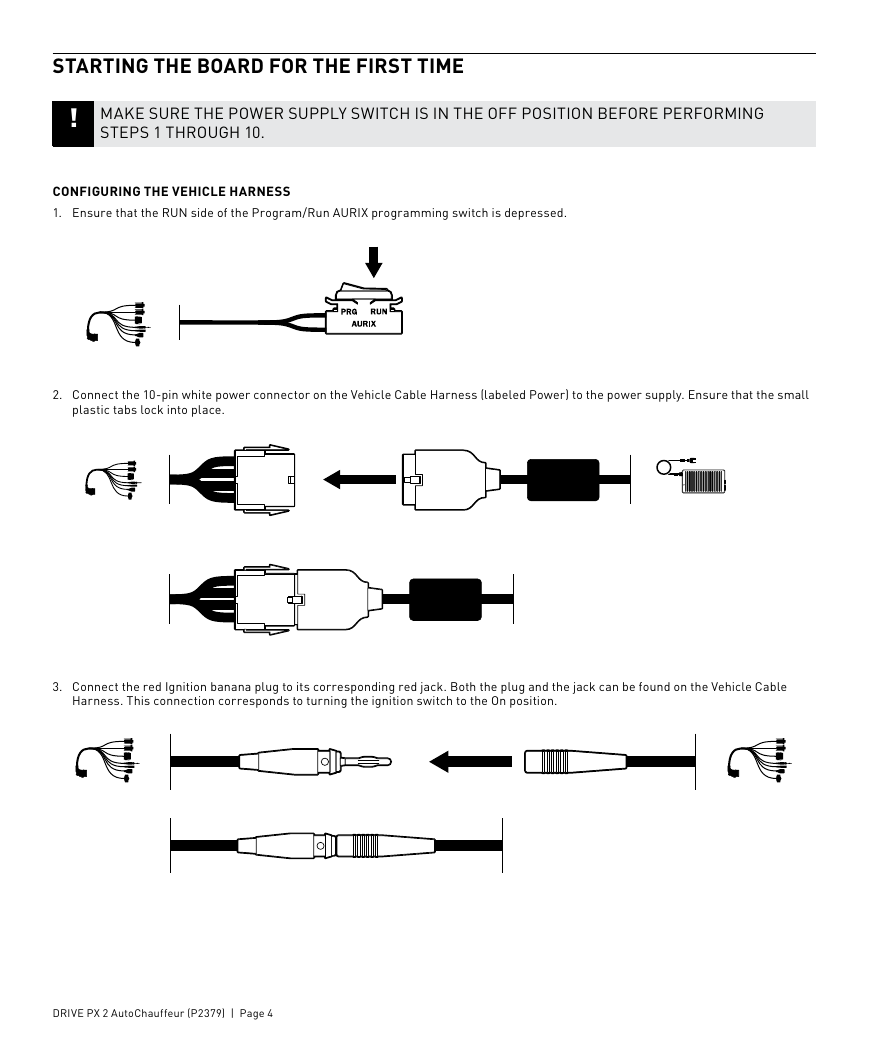
STARTING THE BOARD FOR THE FIRST TIME
! MAKE SURE THE POWER SUPPLY SWITCH IS IN THE OFF POSITION BEFORE PERFORMING
STEPS 1 THROUGH 10.
CONFIGURING THE VEHICLE HARNESS
1. Ensure that the RUN side of the Program/Run AURIX programming switch is depressed.
2. Connect the 10-pin white power connector on the Vehicle Cable Harness (labeled Power) to the power supply. Ensure that the small
plastic tabs lock into place.
3. Connect the red Ignition banana plug to its corresponding red jack. Both the plug and the jack can be found on the Vehicle Cable
Harness. This connection corresponds to turning the ignition switch to the On position.
DRIVE PX 2 AutoChauffeur (P2379) | Page 4
�
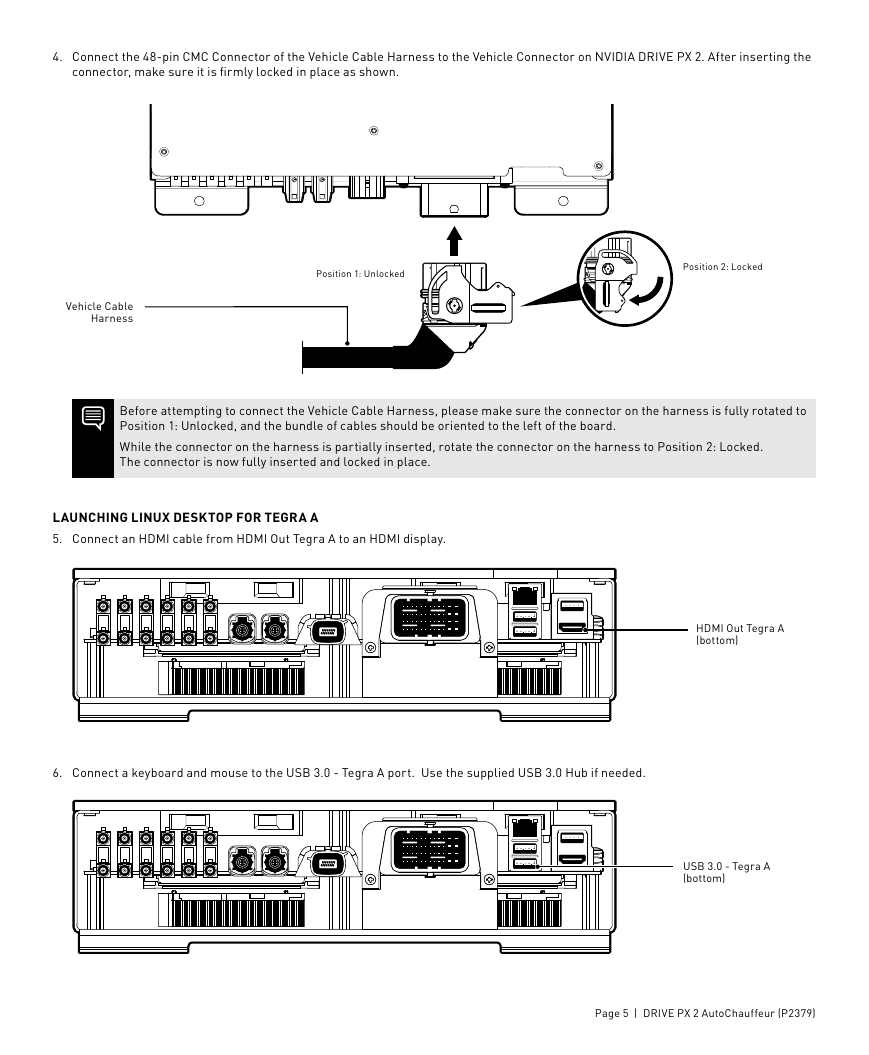
4. Connect the 48-pin CMC Connector of the Vehicle Cable Harness to the Vehicle Connector on NVIDIA DRIVE PX 2. After inserting the
connector, make sure it is firmly locked in place as shown.
Vehicle Cable
Harness
Position 1: Unlocked
Position 2: Locked
Before attempting to connect the Vehicle Cable Harness, please make sure the connector on the harness is fully rotated to
Position 1: Unlocked, and the bundle of cables should be oriented to the left of the board.
While the connector on the harness is partially inserted, rotate the connector on the harness to Position 2: Locked.
The connector is now fully inserted and locked in place.
LAUNCHING LINUX DESKTOP FOR TEGRA A
5. Connect an HDMI cable from HDMI Out Tegra A to an HDMI display.
6. Connect a keyboard and mouse to the USB 3.0 - Tegra A port. Use the supplied USB 3.0 Hub if needed.
HDMI Out Tegra A
(bottom)
USB 3.0 - Tegra A
(bottom)
Page 5 | DRIVE PX 2 AutoChauffeur (P2379)
�
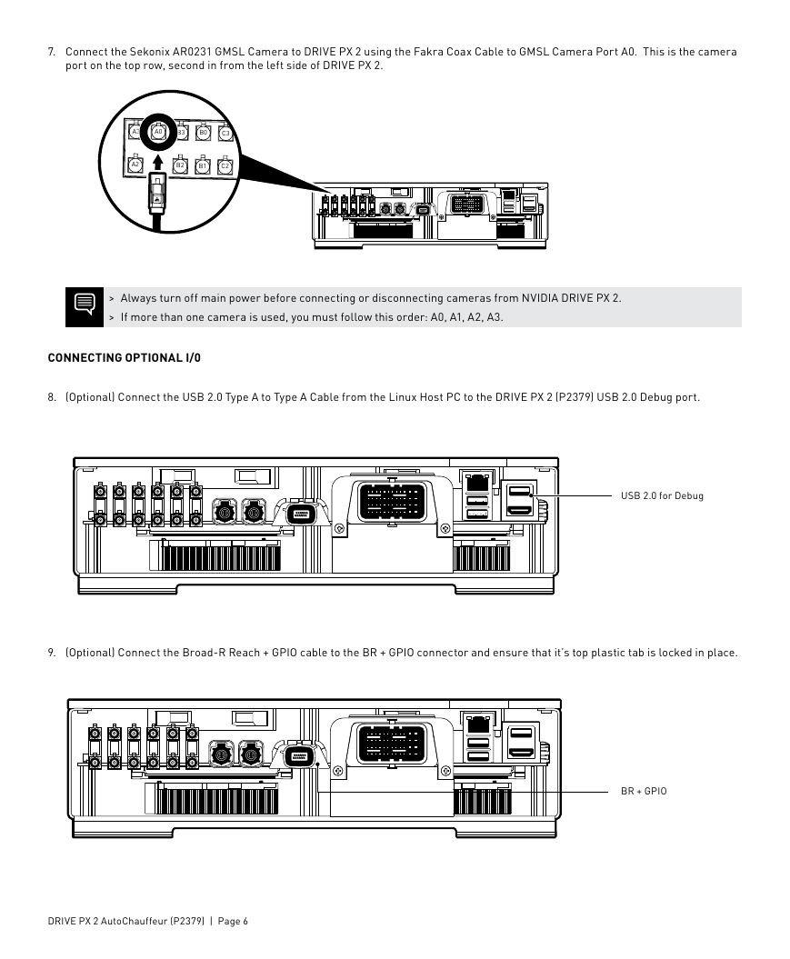
7. Connect the Sekonix AR0231 GMSL Camera to DRIVE PX 2 using the Fakra Coax Cable to GMSL Camera Port A0. This is the camera
port on the top row, second in from the left side of DRIVE PX 2.
A3
A0
B3
B0
C3
C0
A2
B2
B1
C2
C1
> Always turn off main power before connecting or disconnecting cameras from NVIDIA DRIVE PX 2.
> If more than one camera is used, you must follow this order: A0, A1, A2, A3.
CONNECTING OPTIONAL I/0
8. (Optional) Connect the USB 2.0 Type A to Type A Cable from the Linux Host PC to the DRIVE PX 2 (P2379) USB 2.0 Debug port.
USB 2.0 for Debug
9.
(Optional) Connect the Broad-R Reach + GPIO cable to the BR + GPIO connector and ensure that it’s top plastic tab is locked in place.
BR + GPIO
DRIVE PX 2 AutoChauffeur (P2379) | Page 6
�




 2023年江西萍乡中考道德与法治真题及答案.doc
 2012年重庆南川中考生物真题及答案.doc
 2013年江西师范大学地理学综合及文艺理论基础考研真题.doc
 2020年四川甘孜小升初语文真题及答案I卷.doc
 2020年注册岩土工程师专业基础考试真题及答案.doc
 2023-2024学年福建省厦门市九年级上学期数学月考试题及答案.doc
 2021-2022学年辽宁省沈阳市大东区九年级上学期语文期末试题及答案.doc
 2022-2023学年北京东城区初三第一学期物理期末试卷及答案.doc
 2018上半年江西教师资格初中地理学科知识与教学能力真题及答案.doc
 2012年河北国家公务员申论考试真题及答案-省级.doc
 2020-2021学年江苏省扬州市江都区邵樊片九年级上学期数学第一次质量检测试题及答案.doc
 2022下半年黑龙江教师资格证中学综合素质真题及答案.doc