Theory Reference for the Mechanical APDL and Mechanical Applications
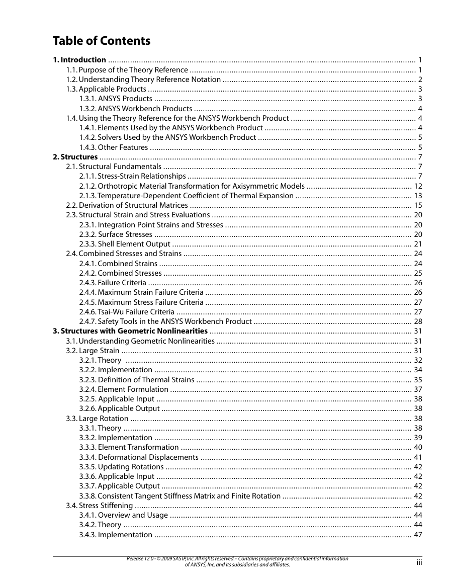
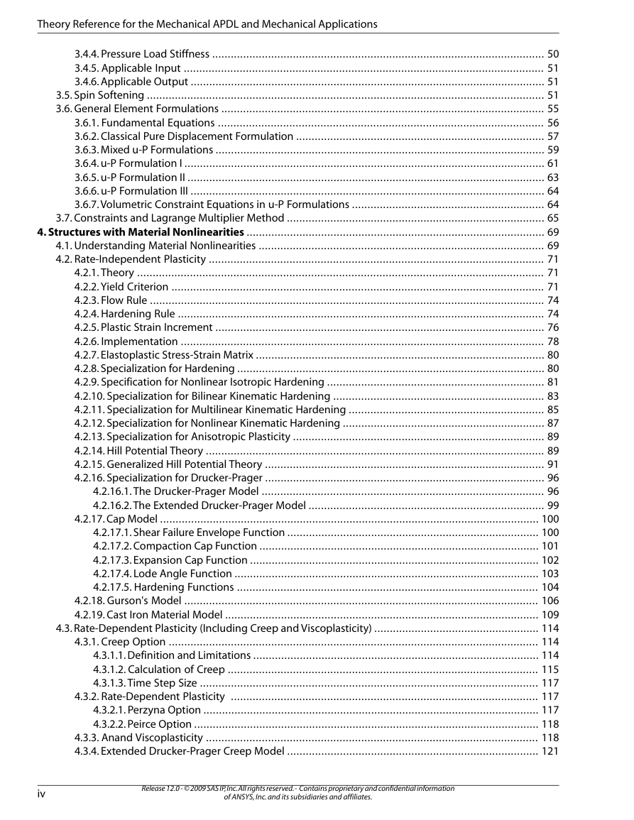
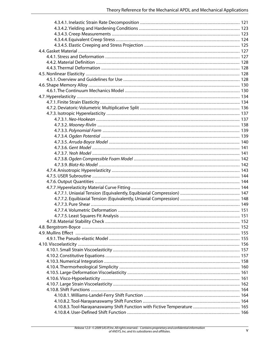
Table of Contents
Chapter 1: Introduction
1.1. Purpose of the Theory Reference
1.2. Understanding Theory Reference Notation
1.3. Applicable Products
1.3.1. ANSYS Products
1.3.2. ANSYS Workbench Products
1.4. Using the Theory Reference for the ANSYS Workbench Product
1.4.1. Elements Used by the ANSYS Workbench Product
1.4.2. Solvers Used by the ANSYS Workbench Product
1.4.3. Other Features
Chapter 2: Structures
2.1. Structural Fundamentals
2.1.1. Stress-Strain Relationships
2.1.2. Orthotropic Material Transformation for Axisymmetric Models
2.1.3. Temperature-Dependent Coefficient of Thermal Expansion
2.2. Derivation of Structural Matrices
2.3. Structural Strain and Stress Evaluations
2.3.1. Integration Point Strains and Stresses
2.3.2. Surface Stresses
2.3.3. Shell Element Output
2.4. Combined Stresses and Strains
2.4.1. Combined Strains
2.4.2. Combined Stresses
2.4.3. Failure Criteria
2.4.4. Maximum Strain Failure Criteria
2.4.5. Maximum Stress Failure Criteria
2.4.6. Tsai-Wu Failure Criteria
2.4.7. Safety Tools in the ANSYS Workbench Product
Chapter 3: Structures with Geometric Nonlinearities
3.1. Understanding Geometric Nonlinearities
3.2. Large Strain
3.2.1. Theory
3.2.2. Implementation
3.2.3. Definition of Thermal Strains
3.2.4. Element Formulation
3.2.5. Applicable Input
3.2.6. Applicable Output
3.3. Large Rotation
3.3.1. Theory
3.3.2. Implementation
3.3.3. Element Transformation
3.3.4. Deformational Displacements
3.3.5. Updating Rotations
3.3.6. Applicable Input
3.3.7. Applicable Output
3.3.8. Consistent Tangent Stiffness Matrix and Finite Rotation
3.4. Stress Stiffening
3.4.1. Overview and Usage
3.4.2. Theory
3.4.3. Implementation
3.4.4. Pressure Load Stiffness
3.4.5. Applicable Input
3.4.6. Applicable Output
3.5. Spin Softening
3.6. General Element Formulations
3.6.1. Fundamental Equations
3.6.2. Classical Pure Displacement Formulation
3.6.3. Mixed u-P Formulations
3.6.4. u-P Formulation I
3.6.5. u-P Formulation II
3.6.6. u-P Formulation III
3.6.7. Volumetric Constraint Equations in u-P Formulations
3.7. Constraints and Lagrange Multiplier Method
Chapter 4: Structures with Material Nonlinearities
4.1. Understanding Material Nonlinearities
4.2. Rate-Independent Plasticity
4.2.1. Theory
4.2.2. Yield Criterion
4.2.3. Flow Rule
4.2.4. Hardening Rule
4.2.5. Plastic Strain Increment
4.2.6. Implementation
4.2.7. Elastoplastic Stress-Strain Matrix
4.2.8. Specialization for Hardening
4.2.9. Specification for Nonlinear Isotropic Hardening
4.2.10. Specialization for Bilinear Kinematic Hardening
4.2.11. Specialization for Multilinear Kinematic Hardening
4.2.12. Specialization for Nonlinear Kinematic Hardening
4.2.13. Specialization for Anisotropic Plasticity
4.2.14. Hill Potential Theory
4.2.15. Generalized Hill Potential Theory
4.2.16. Specialization for Drucker-Prager
4.2.16.1. The Drucker-Prager Model
4.2.16.2. The Extended Drucker-Prager Model
4.2.17. Cap Model
4.2.17.1. Shear Failure Envelope Function
4.2.17.2. Compaction Cap Function
4.2.17.3. Expansion Cap Function
4.2.17.4. Lode Angle Function
4.2.17.5. Hardening Functions
4.2.18. Gurson's Model
4.2.19. Cast Iron Material Model
4.3. Rate-Dependent Plasticity (Including Creep and Viscoplasticity)
4.3.1. Creep Option
4.3.1.1. Definition and Limitations
4.3.1.2. Calculation of Creep
4.3.1.3. Time Step Size
4.3.2. Rate-Dependent Plasticity
4.3.2.1. Perzyna Option
4.3.2.2. Peirce Option
4.3.3. Anand Viscoplasticity
4.3.4. Extended Drucker-Prager Creep Model
4.3.4.1. Inelastic Strain Rate Decomposition
4.3.4.2. Yielding and Hardening Conditions
4.3.4.3. Creep Measurements
4.3.4.4. Equivalent Creep Stress
4.3.4.5. Elastic Creeping and Stress Projection
4.4. Gasket Material
4.4.1. Stress and Deformation
4.4.2. Material Definition
4.4.3. Thermal Deformation
4.5. Nonlinear Elasticity
4.5.1. Overview and Guidelines for Use
4.6. Shape Memory Alloy
4.6.1. The Continuum Mechanics Model
4.7. Hyperelasticity
4.7.1. Finite Strain Elasticity
4.7.2. Deviatoric-Volumetric Multiplicative Split
4.7.3. Isotropic Hyperelasticity
4.7.3.1. Neo-Hookean
4.7.3.2. Mooney-Rivlin
4.7.3.3. Polynomial Form
4.7.3.4. Ogden Potential
4.7.3.5. Arruda-Boyce Model
4.7.3.6. Gent Model
4.7.3.7. Yeoh Model
4.7.3.8. Ogden Compressible Foam Model
4.7.3.9. Blatz-Ko Model
4.7.4. Anisotropic Hyperelasticity
4.7.5. USER Subroutine
4.7.6. Output Quantities
4.7.7. Hyperelasticity Material Curve Fitting
4.7.7.1. Uniaxial Tension (Equivalently, Equibiaxial Compression)
4.7.7.2. Equibiaxial Tension (Equivalently, Uniaxial Compression)
4.7.7.3. Pure Shear
4.7.7.4. Volumetric Deformation
4.7.7.5. Least Squares Fit Analysis
4.7.8. Material Stability Check
4.8. Bergstrom-Boyce
4.9. Mullins Effect
4.9.1. The Pseudo-elastic Model
4.10. Viscoelasticity
4.10.1. Small Strain Viscoelasticity
4.10.2. Constitutive Equations
4.10.3. Numerical Integration
4.10.4. Thermorheological Simplicity
4.10.5. Large-Deformation Viscoelasticity
4.10.6. Visco-Hypoelasticity
4.10.7. Large Strain Viscoelasticity
4.10.8. Shift Functions
4.10.8.1. Williams-Landel-Ferry Shift Function
4.10.8.2. Tool-Narayanaswamy Shift Function
4.10.8.3. Tool-Narayanaswamy Shift Function with Fictive Temperature
4.10.8.4. User-Defined Shift Function
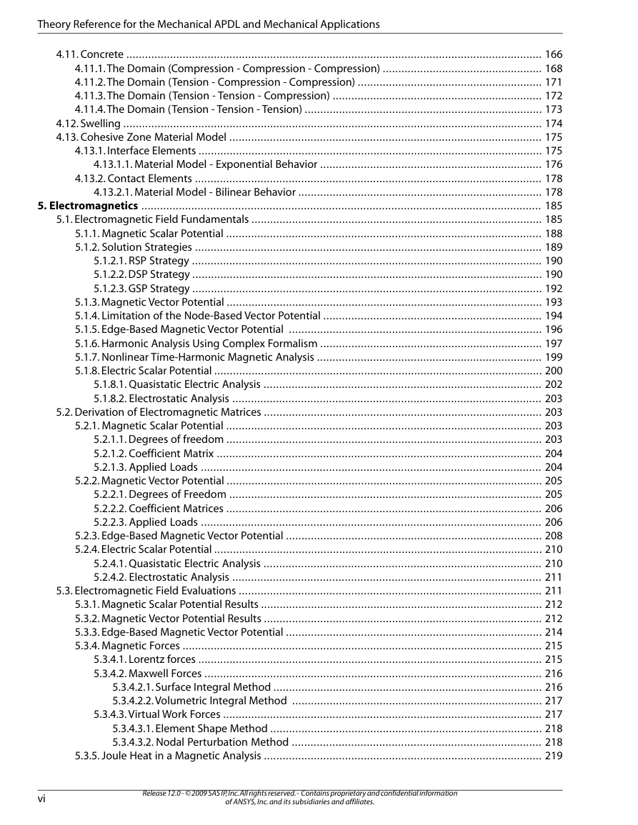
4.11. Concrete
4.11.1. The Domain (Compression - Compression - Compression)
4.11.2. The Domain (Tension - Compression - Compression)
4.11.3. The Domain (Tension - Tension - Compression)
4.11.4. The Domain (Tension - Tension - Tension)
4.12. Swelling
4.13. Cohesive Zone Material Model
4.13.1. Interface Elements
4.13.1.1. Material Model - Exponential Behavior
4.13.2. Contact Elements
4.13.2.1. Material Model - Bilinear Behavior
Chapter 5: Electromagnetics
5.1. Electromagnetic Field Fundamentals
5.1.1. Magnetic Scalar Potential
5.1.2. Solution Strategies
5.1.2.1. RSP Strategy
5.1.2.2. DSP Strategy
5.1.2.3. GSP Strategy
5.1.3. Magnetic Vector Potential
5.1.4. Limitation of the Node-Based Vector Potential
5.1.5. Edge-Based Magnetic Vector Potential
5.1.6. Harmonic Analysis Using Complex Formalism
5.1.7. Nonlinear Time-Harmonic Magnetic Analysis
5.1.8. Electric Scalar Potential
5.1.8.1. Quasistatic Electric Analysis
5.1.8.2. Electrostatic Analysis
5.2. Derivation of Electromagnetic Matrices
5.2.1. Magnetic Scalar Potential
5.2.1.1. Degrees of freedom
5.2.1.2. Coefficient Matrix
5.2.1.3. Applied Loads
5.2.2. Magnetic Vector Potential
5.2.2.1. Degrees of Freedom
5.2.2.2. Coefficient Matrices
5.2.2.3. Applied Loads
5.2.3. Edge-Based Magnetic Vector Potential
5.2.4. Electric Scalar Potential
5.2.4.1. Quasistatic Electric Analysis
5.2.4.2. Electrostatic Analysis
5.3. Electromagnetic Field Evaluations
5.3.1. Magnetic Scalar Potential Results
5.3.2. Magnetic Vector Potential Results
5.3.3. Edge-Based Magnetic Vector Potential
5.3.4. Magnetic Forces
5.3.4.1. Lorentz forces
5.3.4.2. Maxwell Forces
5.3.4.2.1. Surface Integral Method
5.3.4.2.2. Volumetric Integral Method
5.3.4.3. Virtual Work Forces
5.3.4.3.1. Element Shape Method
5.3.4.3.2. Nodal Perturbation Method
5.3.5. Joule Heat in a Magnetic Analysis
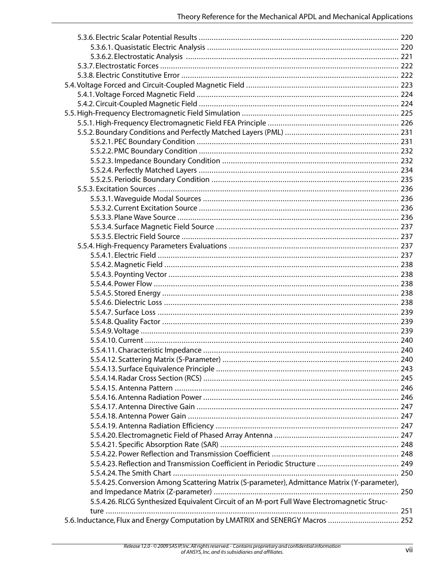
5.3.6. Electric Scalar Potential Results
5.3.6.1. Quasistatic Electric Analysis
5.3.6.2. Electrostatic Analysis
5.3.7. Electrostatic Forces
5.3.8. Electric Constitutive Error
5.4. Voltage Forced and Circuit-Coupled Magnetic Field
5.4.1. Voltage Forced Magnetic Field
5.4.2. Circuit-Coupled Magnetic Field
5.5. High-Frequency Electromagnetic Field Simulation
5.5.1. High-Frequency Electromagnetic Field FEA Principle
5.5.2. Boundary Conditions and Perfectly Matched Layers (PML)
5.5.2.1. PEC Boundary Condition
5.5.2.2. PMC Boundary Condition
5.5.2.3. Impedance Boundary Condition
5.5.2.4. Perfectly Matched Layers
5.5.2.5. Periodic Boundary Condition
5.5.3. Excitation Sources
5.5.3.1. Waveguide Modal Sources
5.5.3.2. Current Excitation Source
5.5.3.3. Plane Wave Source
5.5.3.4. Surface Magnetic Field Source
5.5.3.5. Electric Field Source
5.5.4. High-Frequency Parameters Evaluations
5.5.4.1. Electric Field
5.5.4.2. Magnetic Field
5.5.4.3. Poynting Vector
5.5.4.4. Power Flow
5.5.4.5. Stored Energy
5.5.4.6. Dielectric Loss
5.5.4.7. Surface Loss
5.5.4.8. Quality Factor
5.5.4.9. Voltage
5.5.4.10. Current
5.5.4.11. Characteristic Impedance
5.5.4.12. Scattering Matrix (S-Parameter)
5.5.4.13. Surface Equivalence Principle
5.5.4.14. Radar Cross Section (RCS)
5.5.4.15. Antenna Pattern
5.5.4.16. Antenna Radiation Power
5.5.4.17. Antenna Directive Gain
5.5.4.18. Antenna Power Gain
5.5.4.19. Antenna Radiation Efficiency
5.5.4.20. Electromagnetic Field of Phased Array Antenna
5.5.4.21. Specific Absorption Rate (SAR)
5.5.4.22. Power Reflection and Transmission Coefficient
5.5.4.23. Reflection and Transmission Coefficient in Periodic Structure
5.5.4.24. The Smith Chart
5.5.4.25. Conversion Among Scattering Matrix (S-parameter), Admittance Matrix (Y-parameter), and Impedance Matrix (Z-parameter)
5.5.4.26. RLCG Synthesized Equivalent Circuit of an M-port Full Wave Electromagnetic Structure
5.6. Inductance, Flux and Energy Computation by LMATRIX and SENERGY Macros
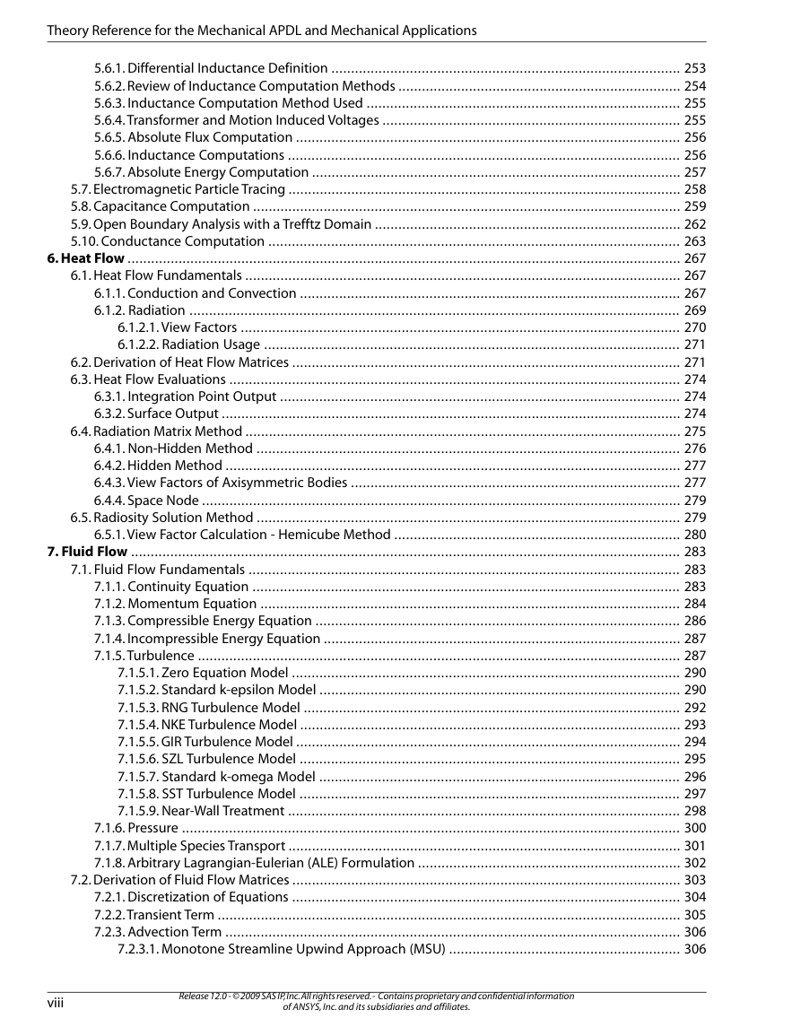
5.6.1. Differential Inductance Definition
5.6.2. Review of Inductance Computation Methods
5.6.3. Inductance Computation Method Used
5.6.4. Transformer and Motion Induced Voltages
5.6.5. Absolute Flux Computation
5.6.6. Inductance Computations
5.6.7. Absolute Energy Computation
5.7. Electromagnetic Particle Tracing
5.8. Capacitance Computation
5.9. Open Boundary Analysis with a Trefftz Domain
5.10. Conductance Computation
Chapter 6: Heat Flow
6.1. Heat Flow Fundamentals
6.1.1. Conduction and Convection
6.1.2. Radiation
6.1.2.1. View Factors
6.1.2.2. Radiation Usage
6.2. Derivation of Heat Flow Matrices
6.3. Heat Flow Evaluations
6.3.1. Integration Point Output
6.3.2. Surface Output
6.4. Radiation Matrix Method
6.4.1. Non-Hidden Method
6.4.2. Hidden Method
6.4.3. View Factors of Axisymmetric Bodies
6.4.4. Space Node
6.5. Radiosity Solution Method
6.5.1. View Factor Calculation - Hemicube Method
Chapter 7: Fluid Flow
7.1. Fluid Flow Fundamentals
7.1.1. Continuity Equation
7.1.2. Momentum Equation
7.1.3. Compressible Energy Equation
7.1.4. Incompressible Energy Equation
7.1.5. Turbulence
7.1.5.1. Zero Equation Model
7.1.5.2. Standard k-epsilon Model
7.1.5.3. RNG Turbulence Model
7.1.5.4. NKE Turbulence Model
7.1.5.5. GIR Turbulence Model
7.1.5.6. SZL Turbulence Model
7.1.5.7. Standard k-omega Model
7.1.5.8. SST Turbulence Model
7.1.5.9. Near-Wall Treatment
7.1.6. Pressure
7.1.7. Multiple Species Transport
7.1.8. Arbitrary Lagrangian-Eulerian (ALE) Formulation
7.2. Derivation of Fluid Flow Matrices
7.2.1. Discretization of Equations
7.2.2. Transient Term
7.2.3. Advection Term
7.2.3.1. Monotone Streamline Upwind Approach (MSU)
7.2.3.2. Streamline Upwind/Petro-Galerkin Approach (SUPG)
7.2.3.3. Collocated Galerkin Approach (COLG)
7.2.4. Diffusion Terms
7.2.5. Source Terms
7.2.6. Segregated Solution Algorithm
7.3. Volume of Fluid Method for Free Surface Flows
7.3.1. Overview
7.3.2. CLEAR-VOF Advection
7.3.3. CLEAR-VOF Reconstruction
7.3.4. Treatment of Finite Element Equations
7.3.5. Treatment of Volume Fraction Field
7.3.6. Treatment of Surface Tension Field
7.4. Fluid Solvers
7.5. Overall Convergence and Stability
7.5.1. Convergence
7.5.2. Stability
7.5.2.1. Relaxation
7.5.2.2. Inertial Relaxation
7.5.2.3. Artificial Viscosity
7.5.3. Residual File
7.5.4. Modified Inertial Relaxation
7.6. Fluid Properties
7.6.1. Density
7.6.2. Viscosity
7.6.3. Thermal Conductivity
7.6.4. Specific Heat
7.6.5. Surface Tension Coefficient
7.6.6. Wall Static Contact Angle
7.6.7. Multiple Species Property Options
7.7. Derived Quantities
7.7.1. Mach Number
7.7.2. Total Pressure
7.7.3. Y-Plus and Wall Shear Stress
7.7.4. Stream Function
7.7.4.1. Cartesian Geometry
7.7.4.2. Axisymmetric Geometry (about x)
7.7.4.3. Axisymmetric Geometry (about y)
7.7.4.4. Polar Coordinates
7.7.5. Heat Transfer Film Coefficient
7.7.5.1. Matrix Procedure
7.7.5.2. Thermal Gradient Procedure
7.7.5.3. Film Coefficient Evaluation
7.8. Squeeze Film Theory
7.8.1. Flow Between Flat Surfaces
7.8.2. Flow in Channels
7.9. Slide Film Theory
Chapter 8: Acoustics
8.1. Acoustic Fluid Fundamentals
8.1.1. Governing Equations
8.1.2. Discretization of the Lossless Wave Equation
8.2. Derivation of Acoustics Fluid Matrices
8.3. Absorption of Acoustical Pressure Wave
8.3.1. Addition of Dissipation due to Damping at the Boundary
8.4. Acoustics Fluid-Structure Coupling
8.5. Acoustics Output Quantities
Chapter 9: This chapter intentionally omitted.
Chapter 10: This chapter intentionally omitted.
Chapter 11: Coupling
11.1. Coupled Effects
11.1.1. Elements
11.1.1.1. Advantages
11.1.1.2. Disadvantages
11.1.2. Coupling Methods
11.1.2.1. Thermal-Structural Analysis
11.1.2.2. Magneto-Structural Analysis (Vector Potential)
11.1.2.3. Magneto-Structural Analysis (Scalar Potential)
11.1.2.4. Electromagnetic Analysis
11.1.2.5. Electro-Thermo-Structural Analysis
11.1.2.6. Electro-Magneto-Thermo-Structural Analysis
11.1.2.7. Electro-Magneto-Thermal Analysis
11.1.2.8. Piezoelectric Analysis
11.1.2.9. Electroelastic Analysis
11.1.2.10. Thermo-Piezoelectric Analysis
11.1.2.11. Piezoresistive Analysis
11.1.2.12. Thermo-Pressure Analysis
11.1.2.13. Velocity-Thermo-Pressure Analysis
11.1.2.14. Pressure-Structural (Acoustic) Analysis
11.1.2.15. Thermo-Electric Analysis
11.1.2.16. Magnetic-Thermal Analysis
11.1.2.17. Circuit-Magnetic Analysis
11.2. Thermoelasticity
11.3. Piezoelectrics
11.4. Electroelasticity
11.5. Piezoresistivity
11.6. Thermoelectrics
11.7. Review of Coupled Electromechanical Methods
11.8. Porous Media Flow
Chapter 12: Shape Functions
12.1. Understanding Shape Function Labels
12.2. 2-D Lines
12.2.1. 2-D Lines without RDOF
12.2.2. 2-D Lines with RDOF
12.3. 3-D Lines
12.3.1. 3-D 2-Node Lines without RDOF
12.3.2. 3-D 2-Node Lines with RDOF
12.3.3. 3-D 3-Node Lines
12.3.4. 3-D 4-Node Lines
12.4. Axisymmetric Shells
12.4.1. Axisymmetric Shell without ESF
12.5. Axisymmetric Harmonic Shells
12.5.1. Axisymmetric Harmonic Shells without ESF
12.5.2. Axisymmetric Harmonic Shells with ESF
12.6. 3-D Shells
12.6.1. 3-D 3-Node Triangular Shells without RDOF (CST)
12.6.2. 3-D 6-Node Triangular Shells without RDOF (LST)
12.6.3. 3-D 3-Node Triangular Shells with RDOF but without SD
12.6.4. 3-D 4-Node Quadrilateral Shells without RDOF and without ESF (Q4)
12.6.5. 3-D 4-Node Quadrilateral Shells without RDOF but with ESF (QM6)
12.6.6. 3-D 8-Node Quadrilateral Shells without RDOF
12.6.7. 3-D 4-Node Quadrilateral Shells with RDOF but without SD and without ESF
12.6.8. 3-D 4-Node Quadrilateral Shells with RDOF but without SD and with ESF
12.7. 2-D and Axisymmetric Solids
12.7.1. 2-D and Axisymmetric 3 Node Triangular Solids (CST)
12.7.2. 2-D and Axisymmetric 6 Node Triangular Solids (LST)
12.7.3. 2-D and Axisymmetric 4 Node Quadrilateral Solid without ESF (Q4)
12.7.4. 2-D and Axisymmetric 4 Node Quadrilateral Solids with ESF (QM6)
12.7.5. 2-D and Axisymmetric 8 Node Quadrilateral Solids (Q8)
12.7.6. 2-D and Axisymmetric 4 Node Quadrilateral Infinite Solids
12.7.6.1. Lagrangian Isoparametric Shape Functions
12.7.6.2. Mapping Functions
12.7.7. 2-D and Axisymmetric 8 Node Quadrilateral Infinite Solids
12.7.7.1. Lagrangian Isoparametric Shape Functions
12.7.7.2. Mapping Functions
12.8. Axisymmetric Harmonic Solids
12.8.1. Axisymmetric Harmonic 3 Node Triangular Solids
12.8.2. Axisymmetric Harmonic 6 Node Triangular Solids
12.8.3. Axisymmetric Harmonic 4 Node Quadrilateral Solids without ESF
12.8.4. Axisymmetric Harmonic 4 Node Quadrilateral Solids with ESF
12.8.5. Axisymmetric Harmonic 8 Node Quadrilateral Solids
12.9. 3-D Solids
12.9.1. 4 Node Tetrahedra
12.9.2. 4 Node Tetrahedra by Condensation
12.9.3. 10 Node Tetrahedra
12.9.4. 10 Node Tetrahedra by Condensation
12.9.5. 5 Node Pyramids by Condensation
12.9.6. 13 Node Pyramids by Condensation
12.9.7. 6 Node Wedges without ESF by Condensation
12.9.8. 6 Node Wedges with ESF by Condensation
12.9.9. 15 Node Wedges by Condensation
12.9.10. 15 Node Wedges Based on Wedge Shape Functions
12.9.11. 8 Node Bricks without ESF
12.9.12. 8 Node Bricks with ESF
12.9.13. 20 Node Bricks
12.9.14. 8 Node Infinite Bricks
12.9.14.1. Lagrangian Isoparametric Shape Functions
12.9.14.2. Mapping Functions
12.9.15. 3-D 20 Node Infinite Bricks
12.9.15.1. Lagrangian Isoparametric Shape Functions
12.9.15.2. Mapping Functions
12.9.16. General Axisymmetric Solids
12.9.16.1. General Axisymmetric Solid with 4 Base Nodes
12.9.16.2. General Axisymmetric Solid with 3 Base Nodes
12.9.16.3. General Axisymmetric Solid with 8 Base Nodes
12.9.16.4. General Axisymmetric Solid with 6 Base Nodes
12.10. Low FrequencyElectromagnetic Edge Elements
12.10.1. 3-D 20 Node Brick (SOLID117)
12.11. High Frequency Electromagnetic Tangential Vector Elements
12.11.1. Tetrahedral Elements (HF119)
12.11.2. Hexahedral Elements (HF120)
12.11.3. Triangular Elements (HF118)
12.11.4. Quadrilateral Elements (HF118)
Chapter 13: Element Tools
13.1. Element Shape Testing
13.1.1. Overview
13.1.2. 3-D Solid Element Faces and Cross-Sections
13.1.3. Aspect Ratio
13.1.4. Aspect Ratio Calculation for Triangles
13.1.5. Aspect Ratio Calculation for Quadrilaterals
13.1.6. Angle Deviation
13.1.7. Angle Deviation Calculation
13.1.8. Parallel Deviation
13.1.9. Parallel Deviation Calculation
13.1.10. Maximum Corner Angle
13.1.11. Maximum Corner Angle Calculation
13.1.12. Jacobian Ratio
13.1.12.1. Jacobian Ratio Calculation
13.1.13. Warping Factor
13.1.13.1. Warping Factor Calculation for Quadrilateral Shell Elements
13.1.13.2. Warping Factor Calculation for 3-D Solid Elements
13.2. Integration Point Locations
13.2.1. Lines (1, 2, or 3 Points)
13.2.2. Quadrilaterals (2 x 2 or 3 x 3 Points)
13.2.3. Bricks and Pyramids (2 x 2 x 2 Points)
13.2.4. Triangles (1, 3, or 6 Points)
13.2.5. Tetrahedra (1, 4, 5, or 11 Points)
13.2.6. Triangles and Tetrahedra (2 x 2 or 2 x 2 x 2 Points)
13.2.7. Wedges (3 x 2 or 3 x 3 Points)
13.2.8. Wedges (2 x 2 x 2 Points)
13.2.9. Bricks (14 Points)
13.2.10. Nonlinear Bending (5 Points)
13.2.11. General Axisymmetric Elements
13.3. Temperature-Dependent Material Properties
13.4. Positive Definite Matrices
13.4.1. Matrices Representing the Complete Structure
13.4.2. Element Matrices
13.5. Lumped Matrices
13.5.1. Diagonalization Procedure
13.5.2. Limitations of Lumped Mass Matrices
13.6. Reuse of Matrices
13.6.1. Element Matrices
13.6.2. Structure Matrices
13.6.3. Override Option
13.7. Hydrodynamic Loads on Line Elements
13.8. Nodal and Centroidal Data Evaluation
Chapter 14: Element Library
14.1. LINK1 - 2-D Spar (or Truss)
14.1.1. Assumptions and Restrictions
14.1.2. Other Applicable Sections
14.2. Not Documented
14.3. BEAM3 - 2-D Elastic Beam
14.3.1. Element Matrices and Load Vectors
14.3.2. Stress Calculation
14.4. BEAM4 - 3-D Elastic Beam
14.4.1. Stiffness and Mass Matrices
14.4.2. Gyroscopic Damping Matrix
14.4.3. Pressure and Temperature Load Vector
14.4.4. Local to Global Conversion
14.4.5. Stress Calculations
14.5. SOLID5 - 3-D Coupled-Field Solid
14.5.1. Other Applicable Sections
14.6. Not Documented
14.7. COMBIN7 - Revolute Joint
14.7.1. Element Description
14.7.2. Element Matrices
14.7.3. Modification of Real Constants
14.8. LINK8 - 3-D Spar (or Truss)
14.8.1. Assumptions and Restrictions
14.8.2. Element Matrices and Load Vector
14.8.3. Force and Stress
14.9. INFIN9 - 2-D Infinite Boundary
14.9.1. Introduction
14.9.2. Theory
14.10. LINK10 - Tension-only or Compression-only Spar
14.10.1. Assumptions and Restrictions
14.10.2. Element Matrices and Load Vector
14.11. LINK11 - Linear Actuator
14.11.1. Assumptions and Restrictions
14.11.2. Element Matrices and Load Vector
14.11.3. Force, Stroke, and Length
14.12. CONTAC12 - 2-D Point-to-Point Contact
14.12.1. Element Matrices
14.12.2. Orientation of the Element
14.12.3. Rigid Coulomb Friction
14.13. PLANE13 - 2-D Coupled-Field Solid
14.13.1. Other Applicable Sections
14.14. COMBIN14 - Spring-Damper
14.14.1. Types of Input
14.14.2. Stiffness Pass
14.14.3. Output Quantities
14.15. Not Documented
14.16. PIPE16 - Elastic Straight Pipe
14.16.1. Other Applicable Sections
14.16.2. Assumptions and Restrictions
14.16.3. Stiffness Matrix
14.16.4. Mass Matrix
14.16.5. Gyroscopic Damping Matrix
14.16.6. Stress Stiffness Matrix
14.16.7. Load Vector
14.16.8. Stress Calculation
14.17. PIPE17 - Elastic Pipe Tee
14.17.1. Other Applicable Sections
14.18. PIPE18 - Elastic Curved Pipe
14.18.1. Other Applicable Sections
14.18.2. Stiffness Matrix
14.18.3. Mass Matrix
14.18.4. Load Vector
14.18.5. Stress Calculations
14.19. Not Documented
14.20. PIPE20 - Plastic Straight Thin-Walled Pipe
14.20.1. Assumptions and Restrictions
14.20.2. Other Applicable Sections
14.20.3. Stress and Strain Calculation
14.21. MASS21 - Structural Mass
14.22. Not Documented
14.23. BEAM23 - 2-D Plastic Beam
14.23.1. Other Applicable Sections
14.23.2. Integration Points
14.23.3. Tangent Stiffness Matrix for Plasticity
14.23.4. Newton-Raphson Load Vector
14.23.5. Stress and Strain Calculation
14.24. BEAM24 - 3-D Thin-walled Beam
14.24.1. Assumptions and Restrictions
14.24.2. Other Applicable Sections
14.24.3. Temperature Distribution Across Cross-Section
14.24.4. Calculation of Cross-Section Section Properties
14.24.5. Offset Transformation
14.25. PLANE25 - Axisymmetric-Harmonic 4-Node Structural Solid
14.25.1. Other Applicable Sections
14.25.2. Assumptions and Restrictions
14.25.3. Use of Temperature
14.26. Not Documented
14.27. MATRIX27 - Stiffness, Damping, or Mass Matrix
14.27.1. Assumptions and Restrictions
14.28. SHELL28 - Shear/Twist Panel
14.28.1. Assumptions and Restrictions
14.28.2. Commentary
14.28.3. Output Terms
14.29. FLUID29 - 2-D Acoustic Fluid
14.29.1. Other Applicable Sections
14.30. FLUID30 - 3-D Acoustic Fluid
14.30.1. Other Applicable Sections
14.31. LINK31 - Radiation Link
14.31.1. Standard Radiation (KEYOPT(3) = 0)
14.31.2. Empirical Radiation (KEYOPT(3) = 1)
14.31.3. Solution
14.32. LINK32 - 2-D Conduction Bar
14.32.1. Other Applicable Sections
14.32.2. Matrices and Load Vectors
14.33. LINK33 - 3-D Conduction Bar
14.33.1. Other Applicable Sections
14.33.2. Matrices and Load Vectors
14.33.3. Output
14.34. LINK34 - Convection Link
14.34.1. Conductivity Matrix
14.34.2. Output
14.35. PLANE35 - 2-D 6-Node Triangular Thermal Solid
14.35.1. Other Applicable Sections
14.36. SOURC36 - Current Source
14.36.1. Description
14.37. COMBIN37 - Control
14.37.1. Element Characteristics
14.37.2. Element Matrices
14.37.3. Adjustment of Real Constants
14.37.4. Evaluation of Control Parameter
14.38. FLUID38 - Dynamic Fluid Coupling
14.38.1. Description
14.38.2. Assumptions and Restrictions
14.38.3. Mass Matrix Formulation
14.38.4. Damping Matrix Formulation
14.39. COMBIN39 - Nonlinear Spring
14.39.1. Input
14.39.2. Element Stiffness Matrix and Load Vector
14.39.3. Choices for Element Behavior
14.40. COMBIN40 - Combination
14.40.1. Characteristics of the Element
14.40.2. Element Matrices for Structural Applications
14.40.3. Determination of F1 and F2 for Structural Applications
14.40.4. Thermal Analysis
14.41. SHELL41 - Membrane Shell
14.41.1. Assumptions and Restrictions
14.41.2. Wrinkle Option
14.42. PLANE42 - 2-D Structural Solid
14.42.1. Other Applicable Sections
14.43. Not Documented
14.44. BEAM44 - 3-D Elastic Tapered Unsymmetric Beam
14.44.1. Other Applicable Sections
14.44.2. Assumptions and Restrictions
14.44.3. Tapered Geometry
14.44.4. Shear Center Effects
14.44.5. Offset at the Ends of the Member
14.44.6. End Moment Release
14.44.7. Local to Global Conversion
14.44.8. Stress Calculations
14.45. SOLID45 - 3-D Structural Solid
14.45.1. Other Applicable Sections
14.46. Not Documented
14.47. INFIN47 - 3-D Infinite Boundary
14.47.1. Introduction
14.47.2. Theory
14.47.3. Reduced Scalar Potential
14.47.4. Difference Scalar Potential
14.47.5. Generalized Scalar Potential
14.48. Not Documented
14.49. Not Documented
14.50. MATRIX50 - Superelement (or Substructure)
14.50.1. Other Applicable Sections
14.51. Not Documented
14.52. CONTAC52 - 3-D Point-to-Point Contact
14.52.1. Other Applicable Sections
14.52.2. Element Matrices
14.52.3. Orientation of Element
14.53. PLANE53 - 2-D 8-Node Magnetic Solid
14.53.1. Other Applicable Sections
14.53.2. Assumptions and Restrictions
14.53.3. VOLT DOF in 2-D and Axisymmetric Skin Effect Analysis
14.54. BEAM54 - 2-D Elastic Tapered Unsymmetric Beam
14.54.1. Derivation of Matrices
14.55. PLANE55 - 2-D Thermal Solid
14.55.1. Other Applicable Sections
14.55.2. Mass Transport Option
14.56. Not Documented
14.57. SHELL57 - Thermal Shell
14.57.1. Other Applicable Sections
14.58. Not Documented
14.59. PIPE59 - Immersed Pipe or Cable
14.59.1. Overview of the Element
14.59.2. Location of the Element
14.59.3. Stiffness Matrix
14.59.4. Mass Matrix
14.59.5. Load Vector
14.59.6. Hydrostatic Effects
14.59.7. Hydrodynamic Effects
14.59.8. Stress Output
14.60. PIPE60 - Plastic Curved Thin-Walled Pipe
14.60.1. Assumptions and Restrictions
14.60.2. Other Applicable Sections
14.60.3. Load Vector
14.60.4. Stress Calculations
14.61. SHELL61 - Axisymmetric-Harmonic Structural Shell
14.61.1. Other Applicable Sections
14.61.2. Assumptions and Restrictions
14.61.3. Stress, Force, and Moment Calculations
14.62. SOLID62 - 3-D Magneto-Structural Solid
14.62.1. Other Applicable Sections
14.63. SHELL63 - Elastic Shell
14.63.1. Other Applicable Sections
14.63.2. Foundation Stiffness
14.63.3. In-Plane Rotational Stiffness
14.63.4. Warping
14.63.5. Options for Non-Uniform Material
14.63.6. Extrapolation of Results to the Nodes
14.64. Not Documented
14.65. SOLID65 - 3-D Reinforced Concrete Solid
14.65.1. Assumptions and Restrictions
14.65.2. Description
14.65.3. Linear Behavior - General
14.65.4. Linear Behavior - Concrete
14.65.5. Linear Behavior - Reinforcement
14.65.6. Nonlinear Behavior - Concrete
14.65.7. Modeling of a Crack
14.65.8. Modeling of Crushing
14.65.9. Nonlinear Behavior - Reinforcement
14.66. Not Documented
14.67. PLANE67 - 2-D Coupled Thermal-Electric Solid
14.67.1. Other Applicable Sections
14.68. LINK68 - Coupled Thermal-Electric Line
14.68.1. Other Applicable Sections
14.69. SOLID69 - 3-D Coupled Thermal-Electric Solid
14.69.1. Other Applicable Sections
14.70. SOLID70 - 3-D Thermal Solid
14.70.1. Other Applicable Sections
14.70.2. Fluid Flow in a Porous Medium
14.71. MASS71 - Thermal Mass
14.71.1. Specific Heat Matrix
14.71.2. Heat Generation Load Vector
14.72. Not Documented
14.73. Not Documented
14.74. Not Documented
14.75. PLANE75 - Axisymmetric-Harmonic 4-Node Thermal Solid
14.75.1. Other Applicable Sections
14.76. Not Documented
14.77. PLANE77 - 2-D 8-Node Thermal Solid
14.77.1. Other Applicable Sections
14.77.2. Assumptions and Restrictions
14.78. PLANE78 - Axisymmetric-Harmonic 8-Node Thermal Solid
14.78.1. Other Applicable Sections
14.78.2. Assumptions and Restrictions
14.79. FLUID79 - 2-D Contained Fluid
14.79.1. Other Applicable Sections
14.80. FLUID80 - 3-D Contained Fluid
14.80.1. Other Applicable Sections
14.80.2. Assumptions and Restrictions
14.80.3. Material Properties
14.80.4. Free Surface Effects
14.80.5. Other Assumptions and Limitations
14.81. FLUID81 - Axisymmetric-Harmonic Contained Fluid
14.81.1. Other Applicable Sections
14.81.2. Assumptions and Restrictions
14.81.3. Load Vector Correction
14.82. PLANE82 - 2-D 8-Node Structural Solid
14.82.1. Other Applicable Sections
14.82.2. Assumptions and Restrictions
14.83. PLANE83 - Axisymmetric-Harmonic 8-Node Structural Solid
14.83.1. Other Applicable Sections
14.83.2. Assumptions and Restrictions
14.84. Not Documented
14.85. Not Documented
14.86. Not Documented
14.87. SOLID87 - 3-D 10-Node Tetrahedral Thermal Solid
14.87.1. Other Applicable Sections
14.88. Not Documented
14.89. Not Documented
14.90. SOLID90 - 3-D 20-Node Thermal Solid
14.90.1. Other Applicable Sections
14.91. Not Documented
14.92. SOLID92 - 3-D 10-Node Tetrahedral Structural Solid
14.92.1. Other Applicable Sections
14.93. Not Documented
14.94. CIRCU94 - Piezoelectric Circuit
14.94.1. Electric Circuit Elements
14.94.2. Piezoelectric Circuit Element Matrices and Load Vectors
14.95. SOLID95 - 3-D 20-Node Structural Solid
14.95.1. Other Applicable Sections
14.96. SOLID96 - 3-D Magnetic Scalar Solid
14.96.1. Other Applicable Sections
14.97. SOLID97 - 3-D Magnetic Solid
14.97.1. Other Applicable Sections
14.98. SOLID98 - Tetrahedral Coupled-Field Solid
14.98.1. Other Applicable Sections
14.99. Not Documented
14.100. Not Documented
14.101. Not Documented
14.102. Not Documented
14.103. Not Documented
14.104. Not Documented
14.105. Not Documented
14.106. Not Documented
14.107. Not Documented
14.108. Not Documented
14.109. TRANS109 - 2-D Electromechanical Transducer
14.110. INFIN110 - 2-D Infinite Solid
14.110.1. Mapping Functions
14.110.2. Matrices
14.111. INFIN111 - 3-D Infinite Solid
14.111.1. Other Applicable Sections
14.112. Not Documented
14.113. Not Documented
14.114. Not Documented
14.115. INTER115 - 3-D Magnetic Interface
14.115.1. Element Matrix Derivation
14.115.2. Formulation
14.116. FLUID116 - Coupled Thermal-Fluid Pipe
14.116.1. Assumptions and Restrictions
14.116.2. Combined Equations
14.116.3. Thermal Matrix Definitions
14.116.4. Fluid Equations
14.117. SOLID117 - 3-D 20-Node Magnetic Edge
14.117.1. Other Applicable Sections
14.117.2. Matrix Formulation of Low Frequency Edge Element and Tree Gauging
14.118. Not Documented
14.119. HF119 - 3-D High-Frequency Magnetic Tetrahedral Solid
14.119.1. Other Applicable Sections
14.119.2. Solution Shape Functions - H (curl) Conforming Elements
14.120. HF120 - High-Frequency Magnetic Brick Solid
14.120.1. Other Applicable Sections
14.120.2. Solution Shape Functions - H(curl) Conforming Element
14.121. PLANE121 - 2-D 8-Node Electrostatic Solid
14.121.1. Other Applicable Sections
14.121.2. Assumptions and Restrictions
14.122. SOLID122 - 3-D 20-Node Electrostatic Solid
14.122.1. Other Applicable Sections
14.123. SOLID123 - 3-D 10-Node Tetrahedral Electrostatic Solid
14.123.1. Other Applicable Sections
14.124. CIRCU124 - Electric Circuit
14.124.1. Electric Circuit Elements
14.124.2. Electric Circuit Element Matrices
14.125. CIRCU125 - Diode
14.125.1. Diode Elements
14.125.2. Norton Equivalents
14.125.3. Element Matrix and Load Vector
14.126. TRANS126 - Electromechanical Transducer
14.127. SOLID127 - 3-D Tetrahedral Electrostatic Solid p-Element
14.127.1. Other Applicable Sections
14.128. SOLID128 - 3-D Brick Electrostatic Solid p-Element
14.128.1. Other Applicable Sections
14.129. FLUID129 - 2-D Infinite Acoustic
14.129.1. Other Applicable Sections
14.130. FLUID130 - 3-D Infinite Acoustic
14.130.1. Mathematical Formulation and F.E. Discretization
14.130.2. Finite Element Discretization
14.131. SHELL131 - 4-Node Layered Thermal Shell
14.131.1. Other Applicable Sections
14.132. SHELL132 - 8-Node Layered Thermal Shell
14.132.1. Other Applicable Sections
14.133. Not Documented
14.134. Not Documented
14.135. Not Documented
14.136. FLUID136 - 3-D Squeeze Film Fluid Element
14.136.1. Other Applicable Sections
14.136.2. Assumptions and Restrictions
14.137. Not Documented
14.138. FLUID138 - 3-D Viscous Fluid Link Element
14.138.1. Other Applicable Sections
14.139. FLUID139 - 3-D Slide Film Fluid Element
14.139.1. Other Applicable Sections
14.140. Not Documented
14.141. FLUID141 - 2-D Fluid-Thermal
14.141.1. Other Applicable Sections
14.142. FLUID142 - 3-D Fluid-Thermal
14.142.1. Other Applicable Sections
14.142.2. Distributed Resistance Main Diagonal Modification
14.142.3. Turbulent Kinetic Energy Source Term Linearization
14.142.4. Turbulent Kinetic Energy Dissipation Rate
14.143. Not Documented
14.144. ROM144 - Reduced Order Electrostatic-Structural
14.144.1. Element Matrices and Load Vectors
14.144.2. Combination of Modal Coordinates and Nodal Displacement at Master Nodes
14.144.3. Element Loads
14.145. PLANE145 - 2-D Quadrilateral Structural Solid p-Element
14.145.1. Other Applicable Sections
14.146. PLANE146 - 2-D Triangular Structural Solid p-Element
14.146.1. Other Applicable Sections
14.147. SOLID147 - 3-D Brick Structural Solid p-Element
14.147.1. Other Applicable Sections
14.148. SOLID148 - 3-D Tetrahedral Structural Solid p-Element
14.148.1. Other Applicable Sections
14.149. Not Documented
14.150. SHELL150 - 8-Node Structural Shell p-Element
14.150.1. Other Applicable Sections
14.150.2. Assumptions and Restrictions
14.150.3. Stress-Strain Relationships
14.151. SURF151 - 2-D Thermal Surface Effect
14.152. SURF152 - 3-D Thermal Surface Effect
14.152.1. Matrices and Load Vectors
14.152.2. Adiabatic Wall Temperature as Bulk Temperature
14.152.3. Film Coefficient Adjustment
14.152.4. Radiation Form Factor Calculation
14.153. SURF153 - 2-D Structural Surface Effect
14.154. SURF154 - 3-D Structural Surface Effect
14.155. Not Documented
14.156. SURF156 - 3-D Structural Surface Line Load Effect
14.157. SHELL157 - Thermal-Electric Shell
14.157.1. Other Applicable Sections
14.158. Not Documented
14.159. Not Documented
14.160. LINK160 - Explicit 3-D Spar (or Truss)
14.161. BEAM161 - Explicit 3-D Beam
14.162. PLANE162 - Explicit 2-D Structural Solid
14.163. SHELL163 - Explicit Thin Structural Shell
14.164. SOLID164 - Explicit 3-D Structural Solid
14.165. COMBI165 - Explicit Spring-Damper
14.166. MASS166 - Explicit 3-D Structural Mass
14.167. LINK167 - Explicit Tension-Only Spar
14.168. SOLID168 - Explicit 3-D 10-Node Tetrahedral Structural Solid
14.169. TARGE169 - 2-D Target Segment
14.169.1. Other Applicable Sections
14.169.2. Segment Types
14.170. TARGE170 - 3-D Target Segment
14.170.1. Introduction
14.170.2. Segment Types
14.170.3. Reaction Forces
14.171. CONTA171 - 2-D 2-Node Surface-to-Surface Contact
14.171.1. Other Applicable Sections
14.172. CONTA172 - 2-D 3-Node Surface-to-Surface Contact
14.172.1. Other Applicable Sections
14.173. CONTA173 - 3-D 4-Node Surface-to-Surface Contact
14.173.1. Other Applicable Sections
14.174. CONTA174 - 3-D 8-Node Surface-to-Surface Contact
14.174.1. Introduction
14.174.2. Contact Kinematics
14.174.3. Frictional Model
14.174.4. Contact Algorithm
14.174.5. Energy and Momentum Conserving Contact
14.174.6. Debonding
14.174.7. Thermal/Structural Contact
14.174.8. Electric Contact
14.174.9. Magnetic Contact
14.175. CONTA175 - 2-D/3-D Node-to-Surface Contact
14.175.1. Other Applicable Sections
14.175.2. Contact Models
14.175.3. Contact Forces
14.176. CONTA176 - 3-D Line-to-Line Contact
14.176.1. Other Applicable Sections
14.176.2. Contact Kinematics
14.176.3. Contact Forces
14.177. CONTA177 - 3-D Line-to-Surface Contact
14.177.1. Other Applicable Sections
14.177.2. Contact Forces
14.178. CONTA178 - 3-D Node-to-Node Contact
14.178.1. Introduction
14.178.2. Contact Algorithms
14.178.3. Element Damper
14.179. PRETS179 - Pretension
14.179.1. Introduction
14.179.2. Assumptions and Restrictions
14.180. LINK180 - 3-D Spar (or Truss)
14.180.1. Assumptions and Restrictions
14.180.2. Element Mass Matrix
14.181. SHELL181 - 4-Node Shell
14.181.1. Other Applicable Sections
14.181.2. Assumptions and Restrictions
14.181.3. Assumed Displacement Shape Functions
14.181.4. Membrane Option
14.181.5. Warping
14.182. PLANE182 - 2-D 4-Node Structural Solid
14.182.1. Other Applicable Sections
14.182.2. Theory
14.183. PLANE183 - 2-D 8-Node Structural Solid
14.183.1. Other Applicable Sections
14.183.2. Assumptions and Restrictions
14.184. MPC184 - Multipoint Constraint
14.184.1. Slider Element
14.184.2. Joint Elements
14.185. SOLID185 - 3-D 8-Node Structural Solid
14.185.1. SOLID185 - 3-D 8-Node Structural Solid
14.185.2. SOLID185 - 3-D 8-Node Layered Solid
14.185.3. Other Applicable Sections
14.185.4. Theory
14.186. SOLID186 - 3-D 20-Node Homogenous/Layered Structural Solid
14.186.1. SOLID186 - 3-D 20-Node Homogenous Structural Solid
14.186.2. SOLID186 - 3-D 20-Node Layered Structural Solid
14.186.3. Other Applicable Sections
14.187. SOLID187 - 3-D 10-Node Tetrahedral Structural Solid
14.187.1. Other Applicable Sections
14.188. BEAM188 - 3-D 2-Node Beam
14.188.1. Assumptions and Restrictions
14.188.2. Stress Evaluation
14.189. BEAM189 - 3-D 3-Node Beam
14.190. SOLSH190 - 3-D 8-Node Layered Solid Shell
14.190.1. Other Applicable Sections
14.190.2. Theory
14.191. Not Documented
14.192. INTER192 - 2-D 4-Node Gasket
14.192.1. Other Applicable Sections
14.193. INTER193 - 2-D 6-Node Gasket
14.193.1. Other Applicable Sections
14.194. INTER194 - 3-D 16-Node Gasket
14.194.1. Element Technology
14.195. INTER195 - 3-D 8-Node Gasket
14.195.1. Other Applicable Sections
14.196. Not Documented
14.197. Not Documented
14.198. Not Documented
14.199. Not Documented
14.200. Not Documented
14.201. Not Documented
14.202. INTER202 - 2-D 4-Node Cohesive
14.202.1. Other Applicable Sections
14.203. INTER203 - 2-D 6-Node Cohesive
14.203.1. Other Applicable Sections
14.204. INTER204 - 3-D 16-Node Cohesive
14.204.1. Element Technology
14.205. INTER205 - 3-D 8-Node Cohesive
14.205.1. Other Applicable Sections
14.206. Not Documented
14.207. Not Documented
14.208. SHELL208 - 2-Node Axisymmetric Shell
14.208.1. Other Applicable Sections
14.208.2. Assumptions and Restrictions
14.209. SHELL209 - 3-Node Axisymmetric Shell
14.209.1. Other Applicable Sections
14.209.2. Assumptions and Restrictions
14.210. Not Documented
14.211. Not Documented
14.212. CPT212 - 2-D 4-Node Coupled Pore-Pressure Mechanical Solid
14.212.1. Other Applicable Sections
14.213. CPT213 - 2-D 8-Node Coupled Pore-Pressure Mechanical Solid
14.213.1. Other Applicable Sections
14.213.2. Assumptions and Restrictions
14.214. COMBI214 - 2-D Spring-Damper Bearing
14.214.1. Matrices
14.214.2. Output Quantities
14.215. CPT215 - 3-D 8-Node Coupled Pore-Pressure Mechanical Solid
14.215.1. Other Applicable Sections
14.216. CPT216 - 3-D 20-Node Coupled Pore-Pressure Mechanical Solid
14.216.1. Other Applicable Sections
14.217. CPT217 - 3-D 10-Node Coupled Pore-Pressure Mechanical Solid
14.217.1. Other Applicable Sections
14.218. Not Documented
14.219. Not Documented
14.220. Not Documented
14.221. Not Documented
14.222. Not Documented
14.223. PLANE223 - 2-D 8-Node Coupled-Field Solid
14.223.1. Other Applicable Sections
14.224. Not Documented
14.225. Not Documented
14.226. SOLID226 - 3-D 20-Node Coupled-Field Solid
14.226.1. Other Applicable Sections
14.227. SOLID227 - 3-D 10-Node Coupled-Field Solid
14.227.1. Other Applicable Sections
14.228. Not Documented
14.229. Not Documented
14.230. PLANE230 - 2-D 8-Node Electric Solid
14.230.1. Other Applicable Sections
14.230.2. Assumptions and Restrictions
14.231. SOLID231 - 3-D 20-Node Electric Solid
14.231.1. Other Applicable Sections
14.232. SOLID232 - 3-D 10-Node Tetrahedral Electric Solid
14.232.1. Other Applicable Sections
14.233. Not Documented
14.234. Not Documented
14.235. Not Documented
14.236. SOLID236 - 3-D 20-Node Electromagnetic Solid
14.236.1. Other Applicable Sections
14.237. SOLID237 - 3-D 10-Node Electromagnetic Solid
14.237.1. Other Applicable Sections
14.238. Not Documented
14.239. Not Documented
14.240. Not Documented
14.241. Not Documented
14.242. Not Documented
14.243. Not Documented
14.244. Not Documented
14.245. Not Documented
14.246. Not Documented
14.247. Not Documented
14.248. Not Documented
14.249. Not Documented
14.250. Not Documented
14.251. SURF251 - 2-D Radiosity Surface
14.252. SURF252 - 3-D Thermal Radiosity Surface
14.253. Not Documented
14.254. Not Documented
14.255. Not Documented
14.256. Not Documented
14.257. Not Documented
14.258. Not Documented
14.259. Not Documented
14.260. Not Documented
14.261. Not Documented
14.262. Not Documented
14.263. Not Documented
14.264. REINF264 - 3-D Discrete Reinforcing
14.264.1. Other Applicable Sections
14.265. REINF265 - 3-D Smeared Reinforcing
14.265.1. Other Applicable Sections
14.265.2. Stiffness and Mass Matrices of a Reinforcing Layer
14.266. Not Documented
14.267. Not Documented
14.268. Not Documented
14.269. Not Documented
14.270. Not Documented
14.271. Not Documented
14.272. SOLID272 - General Axisymmetric Solid with 4 Base Nodes
14.272.1. Other Applicable Sections
14.272.2. Assumptions and Restrictions
14.273. SOLID273 - General Axisymmetric Solid with 8 Base Nodes
14.273.1. Other Applicable Sections
14.273.2. Assumptions and Restrictions
14.274. Not Documented
14.275. Not Documented
14.276. Not Documented
14.277. Not Documented
14.278. Not Documented
14.279. Not Documented
14.280. Not Documented
14.281. SHELL281 - 8-Node Shell
14.281.1. Other Applicable Sections
14.281.2. Assumptions and Restrictions
14.281.3. Membrane Option
14.282. Not Documented
14.283. Not Documented
14.284. Not Documented
14.285. SOLID285 - 3-D 4-Node Tetrahedral Structural Solid with Nodal Pressures
14.285.1. Other Applicable Sections
14.285.2. Theory
14.286. Not Documented
14.287. Not Documented
14.288. PIPE288 - 3-D 2-Node Pipe
14.288.1. Assumptions and Restrictions
14.288.2. Ocean Effects
14.288.2.1. Location of the Element
14.288.2.2. Load Vector
14.288.2.3. Hydrostatic Effects
14.288.2.4. Hydrodynamic Effects
14.288.3. Stress Evaluation
14.289. PIPE289 - 3-D 3-Node Pipe
14.290. ELBOW290 - 3-D 3-Node Elbow
14.290.1. Other Applicable Sections
14.290.2. Assumptions and Restrictions
Chapter 15: Analysis Tools
15.1. Acceleration Effect
15.2. Inertia Relief
15.3. Damping Matrices
15.4. Rotating Structures
15.4.1. Coriolis Matrix and Coriolis Force in a Rotating Reference Frame
15.4.2. Gyroscopic Matrix in a Stationary Reference Frame
15.4.2.1. Kinetic Energy for the Gyroscopic Matrix Calculation of Lumped Mass and Legacy Beam Element
15.4.2.2. General Expression of the Kinetic Energy for the Gyroscopic Matrix Calculation
15.4.3. Rotating Damping Matrix in a Stationary Reference Frame
15.5. Element Reordering
15.5.1. Reordering Based on Topology with a Program-Defined Starting Surface
15.5.2. Reordering Based on Topology with a User- Defined Starting Surface
15.5.3. Reordering Based on Geometry
15.5.4. Automatic Reordering
15.6. Automatic Master Degrees of Freedom Selection
15.7. Automatic Time Stepping
15.7.1. Time Step Prediction
15.7.2. Time Step Bisection
15.7.3. The Response Eigenvalue for 1st Order Transients
15.7.4. The Response Frequency for Structural Dynamics
15.7.5. Creep Time Increment
15.7.6. Plasticity Time Increment
15.7.7. Midstep Residual for Structural Dynamic Analysis
15.8. Solving for Unknowns and Reactions
15.8.1. Reaction Forces
15.8.2. Disequilibrium
15.9. Equation Solvers
15.9.1. Direct Solvers
15.9.2. Sparse Direct Solver
15.9.3. Iterative Solver
15.10. Mode Superposition Method
15.10.1. Modal Damping
15.10.2. Residual Vector Method
15.11. Extraction of Modal Damping Parameter for Squeeze Film Problems
15.12. Reduced Order Modeling of Coupled Domains
15.12.1. Selection of Modal Basis Functions
15.12.2. Element Loads
15.12.3. Mode Combinations for Finite Element Data Acquisition and Energy Computation
15.12.4. Function Fit Methods for Strain Energy
15.12.5. Coupled Electrostatic-Structural Systems
15.12.6. Computation of Capacitance Data and Function Fit
15.13. Newton-Raphson Procedure
15.13.1. Overview
15.13.2. Convergence
15.13.3. Predictor
15.13.4. Adaptive Descent
15.13.5. Line Search
15.13.6. Arc-Length Method
15.14. Constraint Equations
15.14.1. Derivation of Matrix and Load Vector Operations
15.15. This section intentionally omitted
15.16. Eigenvalue and Eigenvector Extraction
15.16.1. Reduced Method
15.16.1.1. Transformation of the Generalized Eigenproblem to a Standard Eigenproblem
15.16.1.2. Reduce [A] to Tridiagonal Form
15.16.1.3. Eigenvalue Calculation
15.16.1.4. Eigenvector Calculation
15.16.1.5. Eigenvector Transformation
15.16.2. Supernode Method
15.16.3. Block Lanczos
15.16.4. PCG Lanczos
15.16.5. Unsymmetric Method
15.16.6. Damped Method
15.16.7. QR Damped Method
15.16.8. Shifting
15.16.9. Repeated Eigenvalues
15.16.10. Complex Eigensolutions
15.17. Analysis of Cyclic Symmetric Structures
15.17.1. Modal Analysis
15.17.2. Complete Mode Shape Derivation
15.17.3. Cyclic Symmetry Transformations
15.18. Mass Moments of Inertia
15.18.1. Accuracy of the Calculations
15.18.2. Effect of KSUM, LSUM, ASUM, and VSUM Commands
15.19. Energies
15.20. ANSYS Workbench Product Adaptive Solutions
Chapter 16: This chapter intentionally omitted.
Chapter 17: Analysis Procedures
17.1. Static Analysis
17.1.1. Assumptions and Restrictions
17.1.2. Description of Structural Systems
17.1.3. Description of Thermal, Magnetic and Other First Order Systems
17.2. Transient Analysis
17.2.1. Assumptions and Restrictions
17.2.2. Description of Structural and Other Second Order Systems
17.2.2.1. Solution
17.2.3. Description of Thermal, Magnetic and Other First Order Systems
17.3. Mode-Frequency Analysis
17.3.1. Assumptions and Restrictions
17.3.2. Description of Analysis
17.4. Harmonic Response Analyses
17.4.1. Assumptions and Restrictions
17.4.2. Description of Analysis
17.4.3. Complex Displacement Output
17.4.4. Nodal and Reaction Load Computation
17.4.5. Solution
17.4.5.1. Full Solution Method
17.4.5.2. Reduced Solution Method
17.4.5.2.1. Expansion Pass
17.4.5.3. Mode Superposition Method
17.4.5.3.1. Expansion Pass
17.4.6. Variational Technology Method
17.4.6.1. Viscous or Hysteretic Damping
17.4.7. Automatic Frequency Spacing
17.4.8. Rotating Forces on Rotating Structures
17.4.8.1. General Asynchronous Rotating Force
17.4.8.2. Specific Synchronous Forces: Mass Unbalance
17.5. Buckling Analysis
17.5.1. Assumptions and Restrictions
17.5.2. Description of Analysis
17.6. Substructuring Analysis
17.6.1. Assumptions and Restrictions (within Superelement)
17.6.2. Description of Analysis
17.6.3. Statics
17.6.4. Transients
17.6.5. Component Mode Synthesis (CMS)
17.7. Spectrum Analysis
17.7.1. Assumptions and Restrictions
17.7.2. Description of Analysis
17.7.3. Single-Point Response Spectrum
17.7.4. Damping
17.7.5. Participation Factors and Mode Coefficients
17.7.6. Combination of Modes
17.7.6.1. Complete Quadratic Combination Method
17.7.6.2. Grouping Method
17.7.6.3. Double Sum Method
17.7.6.4. SRSS Method
17.7.6.5. NRL-SUM Method
17.7.6.6. Rosenblueth Method
17.7.7. Reduced Mass Summary
17.7.8. Effective Mass and Cumulative Mass Fraction
17.7.9. Dynamic Design Analysis Method
17.7.10. Random Vibration Method
17.7.11. Description of Method
17.7.12. Response Power Spectral Densities and Mean Square Response
17.7.12.1. Dynamic Part
17.7.12.2. Pseudo-Static Part
17.7.12.3. Covariance Part
17.7.12.4. Equivalent Stress Mean Square Response
17.7.13. Cross Spectral Terms for Partially Correlated Input PSDs
17.7.14. Spatial Correlation
17.7.15. Wave Propagation
17.7.16. Multi-Point Response Spectrum Method
17.7.17. Missing Mass Response
17.7.18. Rigid Responses
Chapter 18: Preprocessing and Postprocessing Tools
18.1. Integration and Differentiation Procedures
18.1.1. Single Integration Procedure
18.1.2. Double Integration Procedure
18.1.3. Differentiation Procedure
18.1.4. Double Differentiation Procedure
18.2. Fourier Coefficient Evaluation
18.3. Statistical Procedures
18.3.1. Mean, Covariance, Correlation Coefficient
18.3.2. Random Samples of a Uniform Distribution
18.3.3. Random Samples of a Gaussian Distribution
18.3.4. Random Samples of a Triangular Distribution
18.3.5. Random Samples of a Beta Distribution
18.3.6. Random Samples of a Gamma Distribution
Chapter 19: Postprocessing
19.1. POST1 - Derived Nodal Data Processing
19.1.1. Derived Nodal Data Computation
19.2. POST1 - Vector and Surface Operations
19.2.1. Vector Operations
19.2.2. Surface Operations
19.3. POST1 - Path Operations
19.3.1. Defining the Path
19.3.2. Defining Orientation Vectors of the Path
19.3.3. Mapping Nodal and Element Data onto the Path
19.3.4. Operating on Path Data
19.4. POST1 - Stress Linearization
19.4.1. Cartesian Case
19.4.2. Axisymmetric Case (General)
19.4.3. Axisymmetric Case
19.5. POST1 - Fatigue Module
19.6. POST1 - Electromagnetic Macros
19.6.1. Flux Passing Thru a Closed Contour
19.6.2. Force on a Body
19.6.3. Magnetomotive Forces
19.6.4. Power Loss
19.6.5. Terminal Parameters for a Stranded Coil
19.6.6. Energy Supplied
19.6.7. Terminal Inductance
19.6.8. Flux Linkage
19.6.9. Terminal Voltage
19.6.10. Torque on a Body
19.6.11. Energy in a Magnetic Field
19.6.12. Relative Error in Electrostatic or Electromagnetic Field Analysis
19.6.12.1. Electrostatics
19.6.12.1.1. Electric Field
19.6.12.1.2. Electric Flux Density
19.6.12.2. Electromagnetics
19.6.12.2.1. Magnetic Field Intensity
19.6.12.2.2. Magnetic Flux Density
19.6.13. SPARM Macro-Parameters
19.6.14. Electromotive Force
19.6.15. Impedance of a Device
19.6.16. Computation of Equivalent Transmission-line Parameters
19.6.17. Quality Factor
19.7. POST1 - Error Approximation Technique
19.7.1. Error Approximation Technique for Displacement-Based Problems
19.7.2. Error Approximation Technique for Temperature-Based Problems
19.7.3. Error Approximation Technique for Magnetics-Based Problems
19.8. POST1 - Crack Analysis
19.9. POST1 - Harmonic Solid and Shell Element Postprocessing
19.9.1. Thermal Solid Elements (PLANE75, PLANE78)
19.9.2. Structural Solid Elements (PLANE25, PLANE83)
19.9.3. Structural Shell Element (SHELL61)
19.10. POST26 - Data Operations
19.11. POST26 - Response Spectrum Generator (RESP)
19.11.1. Time Step Size
19.12. POST1 and POST26 - Interpretation of Equivalent Strains
19.12.1. Physical Interpretation of Equivalent Strain
19.12.2. Elastic Strain
19.12.3. Plastic Strain
19.12.4. Creep Strain
19.12.5. Total Strain
19.13. POST26 - Response Power Spectral Density
19.14. POST26 - Computation of Covariance
19.15. POST1 and POST26 – Complex Results Postprocessing
19.16. POST1 - Modal Assurance Criterion (MAC)
Chapter 20: Design Optimization
20.1. Introduction to Design Optimization
20.1.1. Feasible Versus Infeasible Design Sets
20.1.2. The Best Design Set
20.1.3. Optimization Methods and Design Tools
20.1.3.1. Single-Loop Analysis Tool
20.1.3.2. Random Tool
20.1.3.3. Sweep Tool
20.1.3.4. Factorial Tool
20.1.3.5. Gradient Tool
20.2. Subproblem Approximation Method
20.2.1. Function Approximations
20.2.2. Minimizing the Subproblem Approximation
20.2.3. Convergence
20.3. First Order Optimization Method
20.3.1. The Unconstrained Objective Function
20.3.2. The Search Direction
20.3.3. Convergence
20.4. Topological Optimization
20.4.1. General Optimization Problem Statement
20.4.2. Maximum Static Stiffness Design
20.4.3. Minimum Volume Design
20.4.4. Maximum Dynamic Stiffness Design
20.4.4.1. Weighted Formulation
20.4.4.2. Reciprocal Formulation
20.4.4.3. Euclidean Norm Formulation
20.4.5. Element Calculations
Chapter 21: Probabilistic Design
21.1. Uses for Probabilistic Design
21.2. Probabilistic Modeling and Preprocessing
21.2.1. Statistical Distributions for Random Input Variables
21.2.1.1. Gaussian (Normal) Distribution
21.2.1.2. Truncated Gaussian Distribution
21.2.1.3. Lognormal Distribution
21.2.1.4. Triangular Distribution
21.2.1.5. Uniform Distribution
21.2.1.6. Exponential Distribution
21.2.1.7. Beta Distribution
21.2.1.8. Gamma Distribution
21.2.1.9. Weibull Distribution
21.3. Probabilistic Methods
21.3.1. Introduction
21.3.2. Common Features for all Probabilistic Methods
21.3.2.1. Random Numbers with Standard Uniform Distribution
21.3.2.2. Non-correlated Random Numbers with an Arbitrary Distribution
21.3.2.3. Correlated Random Numbers with an Arbitrary Distribution
21.3.3. Monte Carlo Simulation Method
21.3.3.1. Direct Monte Carlo Simulation
21.3.3.2. Latin Hypercube Sampling
21.3.4. The Response Surface Method
21.3.4.1. Central Composite Design
21.3.4.2. Box-Behnken Matrix Design
21.4. Regression Analysis for Building Response Surface Models
21.4.1. General Definitions
21.4.2. Linear Regression Analysis
21.4.3. F-Test for the Forward-Stepwise-Regression
21.4.4. Transformation of Random Output Parameter Values for Regression Fitting
21.4.5. Goodness-of-Fit Measures
21.4.5.1. Error Sum of Squares SSE
21.4.5.2. Coefficient of Determination R2
21.4.5.3. Maximum Absolute Residual
21.5. Probabilistic Postprocessing
21.5.1. Statistical Procedures
21.5.1.1. Mean Value
21.5.1.2. Standard Deviation
21.5.1.3. Minimum and Maximum Values
21.5.2. Correlation Coefficient Between Sampled Data
21.5.2.1. Pearson Linear Correlation Coefficient
21.5.2.2. Spearman Rank-Order Correlation Coefficient
21.5.3. Cumulative Distribution Function
21.5.4. Evaluation of Probabilities From the Cumulative Distribution Function
21.5.5. Inverse Cumulative Distribution Function
Bibliography
Index


 2023年江西萍乡中考道德与法治真题及答案.doc
 2012年重庆南川中考生物真题及答案.doc
 2013年江西师范大学地理学综合及文艺理论基础考研真题.doc
 2020年四川甘孜小升初语文真题及答案I卷.doc
 2020年注册岩土工程师专业基础考试真题及答案.doc
 2023-2024学年福建省厦门市九年级上学期数学月考试题及答案.doc
 2021-2022学年辽宁省沈阳市大东区九年级上学期语文期末试题及答案.doc
 2022-2023学年北京东城区初三第一学期物理期末试卷及答案.doc
 2018上半年江西教师资格初中地理学科知识与教学能力真题及答案.doc
 2012年河北国家公务员申论考试真题及答案-省级.doc
 2020-2021学年江苏省扬州市江都区邵樊片九年级上学期数学第一次质量检测试题及答案.doc
 2022下半年黑龙江教师资格证中学综合素质真题及答案.doc