MT7530 Giga Switch Programming Guide
Version:
Release date:
06
2014-8-18
© 2008 - 2014 MediaTek Inc.
This document contains information that is proprietary to MediaTek Inc.
Unauthorized reproduction or disclosure of this information in whole or in part is strictly
prohibited.
Specifications are subject to change without notice.
�
Document Revision History
Revision
Date
V00
V01
V02
2013/07/10
2013/09/10
2014/01/29
Author
JayYC
JayYC
JayYC
Note
Initial release
Draft version
1. Add Broadcast Storm suppression
2. Add TrTCM setting
3. Add QoS
4. Add ingress & egress rate control
V03
V04,V05
2014/04/25
2014/08/11
V06
V07
2014/08/18
2014/10/12
JayYC
JayYC
JayYC
JayYC
Update switch configuration
DSCP
Loop detection
VLAN ID translation
�
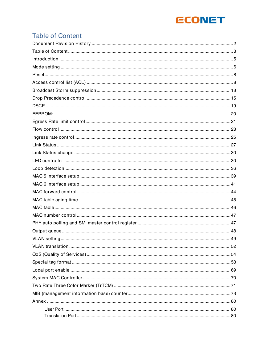
Table of Content
Document Revision History .................................................................................................................. 2
Table of Content ..................................................................................................................................... 3
Introduction ............................................................................................................................................ 5
Mode setting ........................................................................................................................................... 6
Reset ........................................................................................................................................................ 8
Access control list (ACL) ...................................................................................................................... 8
Broadcast Storm suppression ............................................................................................................ 13
Drop Precedence control .................................................................................................................... 15
DSCP ..................................................................................................................................................... 19
EEPROM:............................................................................................................................................... 20
Egress Rate limit control ..................................................................................................................... 21
Flow control .......................................................................................................................................... 23
Ingress rate control .............................................................................................................................. 25
Link Status ............................................................................................................................................ 27
Link Status change .............................................................................................................................. 30
LED controller ...................................................................................................................................... 30
Loop detection ..................................................................................................................................... 36
MAC 5 interface setup ......................................................................................................................... 39
MAC 6 interface setup ......................................................................................................................... 41
MAC forward control ............................................................................................................................ 44
MAC table aging time ........................................................................................................................... 45
MAC table .............................................................................................................................................. 46
MAC number control ............................................................................................................................ 47
PHY auto polling and SMI master control register ........................................................................... 47
Output queue ........................................................................................................................................ 48
VLAN setting ......................................................................................................................................... 49
VLAN translation .................................................................................................................................. 52
QoS (Quality of Services) .................................................................................................................... 54
Special tag format ................................................................................................................................ 58
Local port enable ................................................................................................................................. 69
System MAC Controller ....................................................................................................................... 70
Two Rate Three Color Marker (TrTCM) .............................................................................................. 71
MIB (management information base) counter................................................................................... 73
Annex .................................................................................................................................................... 80
User Port ...................................................................................................................................... 80
Translation Port ............................................................................................................................ 80
�
Transparent Port .......................................................................................................................... 80
Security mode .............................................................................................................................. 80
Check mode ................................................................................................................................. 80
Fallback mode .............................................................................................................................. 81
Port Matrix mode .......................................................................................................................... 81
�
Introduction
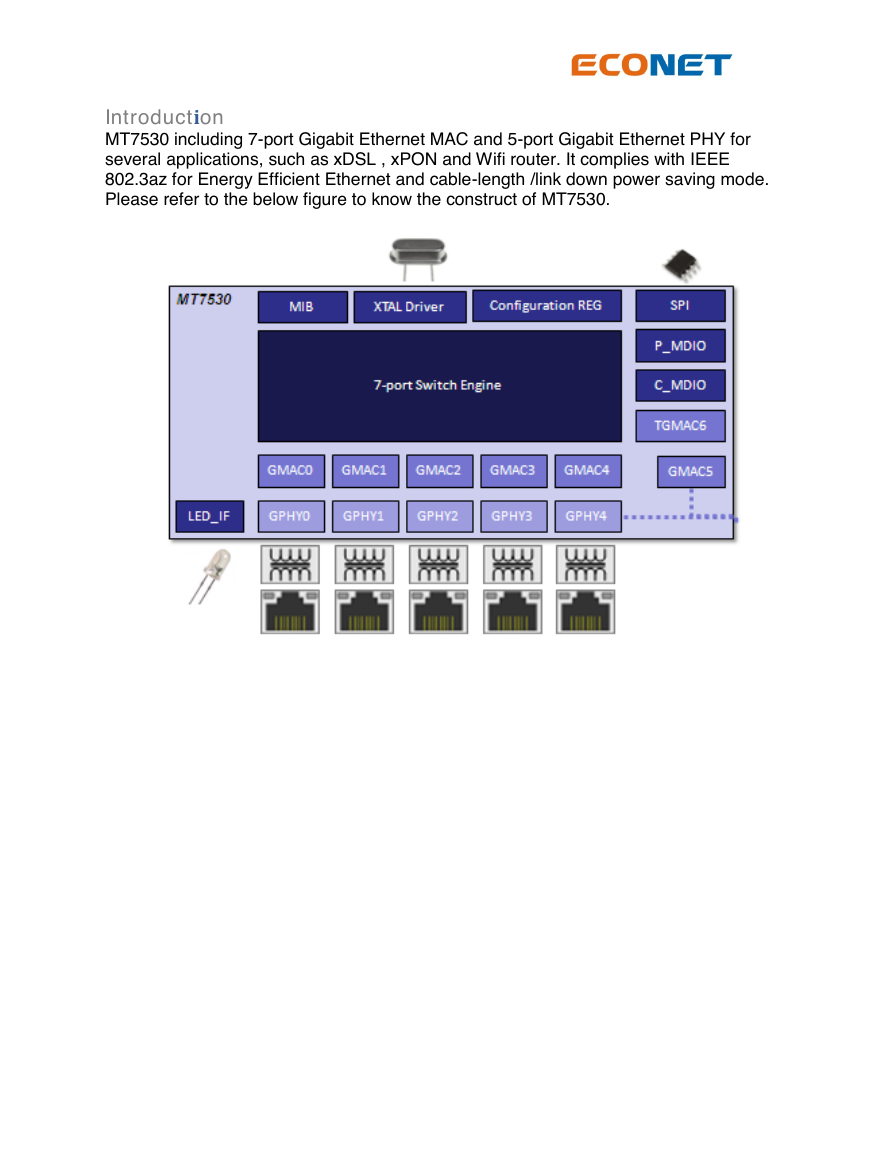
MT7530 including 7-port Gigabit Ethernet MAC and 5-port Gigabit Ethernet PHY for
several applications, such as xDSL , xPON and Wifi router. It complies with IEEE
802.3az for Energy Efficient Ethernet and cable-length /link down power saving mode.
Please refer to the below figure to know the construct of MT7530.
�
Mode setting
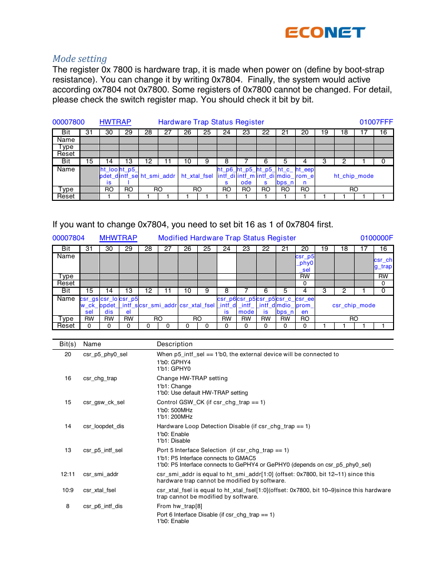
The register 0x 7800 is hardware trap, it is made when power on (define by boot-strap
resistance). You can change it by writing 0x7804. Finally, the system would active
according ox7804 not 0x7800. Some registers of 0x7800 cannot be changed. For detail,
please check the switch register map. You should check it bit by bit.
00007800
HWTRAP
Hardware Trap Status Register
01007FFF
Bit
31
30
29
28
27
26
25
24
23
22
21
20
19
18
17
16
Name
Type
Reset
Bit
15
14
13
12
11
10
9
8
7
6
5
4
3
2
1
0
Name
Type
Reset
ht_loo
pdet_d
ht_p5_
intf_se
is
RO
1
l
RO
1
ht_smi_addr ht_xtal_fsel
RO
RO
1
1
1
1
ht_p6_
intf_di
s
RO
1
ht_p5_
intf_m
ode
RO
1
ht_p5_
intf_di
s
RO
1
ht_eep
rom_e
ht_c_
mdio_
bps_n
n
RO
1
RO
1
ht_chip_mode
RO
1
1
1
1
If you want to change 0x7804, you need to set bit 16 as 1 of 0x7804 first.
00007804
MHWTRAP
Modified Hardware Trap Status Register
0100000F
Bit
31
30
29
28
27
26
Name
Type
Reset
Bit
15
14
13
12
11
10
25
24
23
22
21
9
8
7
6
5
20
csr_p5
_phy0
_sel
RW
0
4
19
18
17
16
csr_ch
g_trap
3
2
1
RW
0
0
Name csr_gs
w_ck_
csr_lo
opdet_
csr_p5
_intf_s
csr_smi_addr csr_xtal_fsel
csr_p6
_intf_d
dis
el
sel
RW RW RW
RO
RO
Type
Reset
0
0
0
0
0
0
0
0
0
0
0
csr_p5
_intf_d
csr_p5
_intf_
mode
csr_c_
mdio_
bps_n
is
RW RW RW RW
is
csr_ee
prom_
en
RO
0
csr_chip_mode
RO
1
1
1
1
Bit(s) Name
Description
20
csr_p5_phy0_sel
16
csr_chg_trap
15
csr_gsw_ck_sel
14
csr_loopdet_dis
13
csr_p5_intf_sel
12:11
csr_smi_addr
10:9
csr_xtal_fsel
8
csr_p6_intf_dis
When p5_intf_sel == 1'b0, the external device will be connected to
1'b0: GPHY4
1'b1: GPHY0
Change HW-TRAP setting
1'b1: Change
1'b0: Use default HW-TRAP setting
Control GSW_CK (if csr_chg_trap == 1)
1'b0: 500MHz
1'b1: 200MHz
Hardware Loop Detection Disable (if csr_chg_trap == 1)
1'b0: Enable
1'b1: Disable
Port 5 Interface Selection (if csr_chg_trap == 1)
1'b1: P5 Interface connects to GMAC5
1'b0: P5 Interface connects to GePHY4 or GePHY0 (depends on csr_p5_phy0_sel)
csr_smi_addr is equal to ht_smi_addr[1:0] (offset: 0x7800, bit 12~11) since this
hardware trap cannot be modified by software.
csr_xtal_fsel is equal to ht_xtal_fsel[1:0](offset: 0x7800, bit 10~9)since this hardware
trap cannot be modified by software.
From hw_trap[8]
Port 6 Interface Disable (if csr_chg_trap == 1)
1'b0: Enable
�
7
csr_p5_intf_mode
6
csr_p5_intf_dis
5
csr_c_mdio_bps_n
1'b1: Disable
Port 5 Interface Mode (if csr_chg_trap == 1)
1'b0: GMII/MII
1'b1: RGMII
Port 5 Interface Disable (if csr_chg_trap == 1)
1'b1: Disable
1'b0: Enable
Directly access phy mdc (if csr_chg_trap==1)
0: Directly access PHY registers via C_MDC/C_MDIO
1: Indirectly access PHY registers
4
csr_eeprom_en
3:0
csr_chip_mode
csr_eeprom_en is equal to ht_eeprom_en (offset: 0x7800, bit 4) since this hardware
trap cannot be modified by software.
csr_chip_mode is equal to ht_chip_mode[3:0] (offset: 0x7800, bit 3~0) since this
hardware trap cannot be modified by software.
Please also check the detail hardware strapping of MT7530.
Pin Name
P4_LED_0
P3_LED_0
Type
I/O
Pin Number
99
102
Description
Crystal clock frequency selection
{P4_LED_0, P3_LED_0} signals are used to control the crystal
clock input frequency to XO and XI.
00: Reserved.
01: 20MHz
10: 40MHz
11: 25MHz (default)
SMI Address selection
{P3_LED_2, P3_LED_1} signals are used to define decoded
Serial Management Interface(SMI) addresses of
C_MDC/C_MDIO for command registers access
00 : Use 7 to 12 SMI addresses
01 : Use 15 to 20 SMI addresses
10 : Use 23 to 28 SMI addresses
11 : Use 31 and 0 to 4 SMI addresses (default)
SMI Access control
0: PHY access mode 0
1: PHY access mode 1 (default)
P5 Interface Disable
0: Enable P5 IO
1: Disable P5 IO (default)
P5 Interface Mode
0: GMII or MII mode
1: RGMII mode (default)
P5 Interface Selection
0: P5 IO is connected to GPHY4
1: P5 IO is connected to GMAC5 (default)
P6 Interface Disable
P3_LED_2
P3_LED_1
P1_LED_1
P1_LED_2
P2_LED_1
P4_LED_1
P2_LED_2
I/O
I/O
I/O
I/O
I/O
I/O
100
101
107
106
104
98
103
�
Pin Name
Type
Pin Number
P0_LED_2
P4_LED_2
I/O
I/O
109
97
Description
0: Enable P6 IO
1: Disable P6 IO (default)
EEPROM Auto Initialization
0: Disable EEPROM auto initialization
1: Enable EEPROM auto initialization (default)
Loop Detection Alarm
0: Enable loop detection
1: Disable loop detection (default)
*Note 1: We would suggest that SMI address of MT7530 is 5’b11111. If not, you need to
change the driver of MT7530.
Reset
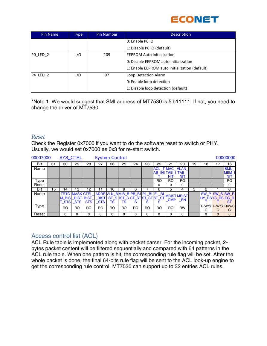
Check the Register 0x7000 if you want to do the software reset to switch or PHY.
Usually, we would set 0x7000 as 0x3 for re-start switch.
00007000
SYS_CTRL
System Control
00000000
Bit
31
30
29
28
27
26
19
18
17
16
BMU_
MEM_I
NIT
RO
0
0
3
2
1
SW_P
HY_RS
SW_S
YS_RS
T
T
SW_R
EG_R
ST
R/W/S
R/W/S
R/W/S
C
0
C
0
C
0
14
TRTC
M_BIS
T_STS
13
12
MASK
_BIST
_STS
CTRL_
BIST_
STS
11
ADDR
_BIST
_STS
25
24
23
9
8
7
22
ACL_T
AB_INI
T
RO
0
6
10
VLN_B
IST_S
MIB_B
IST_S
PB_BI
ST_ST
PL_BI
ST_ST
FL_BI
ST_ST
TS
TS
S
S
S
21
MAC_
TAB_I
NIT
RO
0
5
20
VLAN_
TAB_I
NIT
RO
0
4
MBIST
_CMP
MBIST
_EN
RO
RO
RO
RO
RO
RO
RO
RO
RO
RO
RW
0
0
0
0
0
0
0
0
0
0
0
Name
Type
Reset
Bit
15
Name
Type
Reset
Access control list (ACL)
ACL Rule table is implemented along with packet parser. For the incoming packet, 2-
bytes packet content will be filtered sequentially and compared with 64 patterns in the
ACL rule table. When one pattern is hit, the corresponding rule flag will be set. After the
whole packet is done, the final 64-bits rule flag will be sent to the ACL look-up engine to
get the corresponding rule control. MT7530 can support up to 32 entries ACL rules.
�





 2023年江西萍乡中考道德与法治真题及答案.doc
 2012年重庆南川中考生物真题及答案.doc
 2013年江西师范大学地理学综合及文艺理论基础考研真题.doc
 2020年四川甘孜小升初语文真题及答案I卷.doc
 2020年注册岩土工程师专业基础考试真题及答案.doc
 2023-2024学年福建省厦门市九年级上学期数学月考试题及答案.doc
 2021-2022学年辽宁省沈阳市大东区九年级上学期语文期末试题及答案.doc
 2022-2023学年北京东城区初三第一学期物理期末试卷及答案.doc
 2018上半年江西教师资格初中地理学科知识与教学能力真题及答案.doc
 2012年河北国家公务员申论考试真题及答案-省级.doc
 2020-2021学年江苏省扬州市江都区邵樊片九年级上学期数学第一次质量检测试题及答案.doc
 2022下半年黑龙江教师资格证中学综合素质真题及答案.doc