NVP6134C
Datasheet
4-CH Universal RX(up to 5M NRT) and 5-CH Audio Codec
Web : www.nextchip.com
E-mail : sales@nextchip.com
Tel : +82-2-3460-4700
Information contained here is subject to change without notice.
Make sure to check and use an updated version of the Data Sheet.
�
Rev.
Date.
REV 0.0
REV 1.0
Description
Initial Draft
2016-06-08
2016-10-12 Adding AHD 4M/5M NRT
REVISION HISTORY
NVP6134C Data sheet
Note
-
-
-
-
-
-
© Copyright Nextchip Corporations, Ltd., 2016
All Rights Reserved.
Printed in Korea 2016
Nextchip and the Nextchip Logo are trademarks of Nextchip Corporation in Korea and/or other countries.
Other company, product and service names may be trademarks or service marks of others.
All information contained in this document is subject to change without notice. The products described in this document are NOT intended for
use in implantation or other life support application where malfunction may result in injury or death to persons. The information contained in
this document does not affect or change Nextchip's product specification or warranties. Nothing in this document shall operate as an express
or implied license or indemnity under the intellectual property rights of Nextchip or third parties. All information contained in this document was
obtained in specific environments, and is presented as an illustration. The results obtained in other operating environments may vary.
THE INFORMATION CONTAINED IN THIS DOCUMENT IS PROVIDED ON AN “AS IS” BASIS. In no event will Nextchip be liable for
damages arising directly or indirectly from any use of the information contained in this document.
Nextchip Corporation Ltd
8F, Twosun Venture Forum Bldg., 323, Pangyo-ro, Bundang-gu, Seongnam-si, Gyeonggi-do, Korea 463-400
Nextchip's home page can be found at:
http://www.nextchip.com
�
Product Overview
NVP6134C includes Universal 4-Channel RX and 5-Channel Audio Codec. It delivers high quality CVBS, 1M, 2M and 3/4/5M NRT image. It
accepts separate CVBS, COMET, Universal 1M, 2M and 3/4/5M NRT inputs from Camera and the other video signal sources. It digitizes and
decodes CVBS, COMET, Universal 1M/2M and 3/4/5M NRT Analog video signal into digital video components which represents 8-bit
BT.656/BT.1120 4:2:2 byte interleave format with 74.25,148.5 and 297MHz multiplexed.
NVP6134C includes Clock PLL, so each output byte interleave function available. Especially, It is able to use same transmission cable with
conventional one for COMET(SD level), 1M(HD level), 2M(FHD level) and 3/4/5M NRT, and they provide the superior-image quality by
minimizing the interference when separating Y and C.
5-Channel Audio Codec is 4-Channel Voice/1-Channel Mic PCM Codec which handles voice band signals(300Hz~3400Hz) with 8bit/16bit
linear PCM, 8bit G.711(u-law, a-law) PCM. Built-in audio controller can generate digital outputs for recording/mixing and accepts digital input
for playback.
4-Channel Universal Coaxial Communication Protocol communicates between controller(DVR) and camera on the video signal through
coaxial cable.
Features
1. Video Decoder
Input Formats
- 4CH Video Input
: CVBS / COMET
: Universal 1M, 2M and 3/4/5M NRT
Output Formats
- Output in BT.656/BT.1120 4:2:2 byte interleave format with
37.125/74.25/148.5/297MHz
- Support Sync Separate BT.601 Format (CLK/ H,V-SYNC/ 8’bit
DATA)
Image Signal Processor
-. Support Video Standard Auto-Detection up to 5M NRT for Each CH
-. Support 2*Video Output Port, Each Port Video Output Format
Selectable
-. On Chip Analog CLAMP/Anti-aliasing Filter and EQ Filter
-. Accepts CVBS,COMET, 720P@25p/30p/50p/60p,
1080P@25p/30p, 1536P@18p, 1440@15p, 1944@12.5p
-. Robust Sync detection for weak and unstable signals
-. High-performance adaptive comb filter and Notch Filter
-. Programmable H/V Peaking filter for Luminance
-. CTI (Chrominance Transient Improvement)
-. Color compensation for PAL
-. IF compensation filter
-. Robust No-video detection
-. Programmable Brightness, Contrast, Saturation and Hue
-. Programmable Picture Quality Control
-. Programmable Gamma Correction
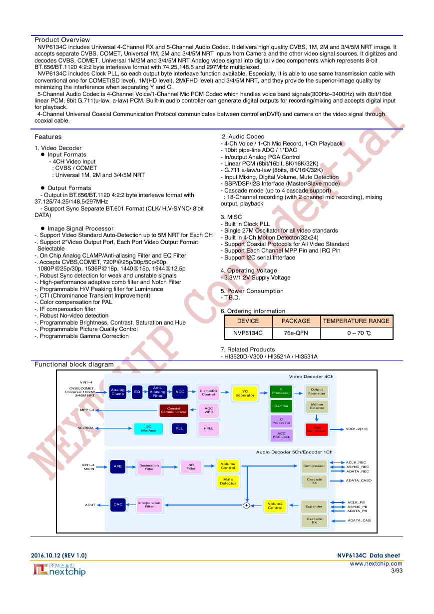
Functional block diagram
2. Audio Codec
- 4-Ch Voice / 1-Ch Mic Record, 1-Ch Playback
- 10bit pipe-line ADC / 1*DAC
- In/output Analog PGA Control
- Linear PCM (8bit/16bit, 8K/16K/32K)
- G.711 a-law/u-law (8bits, 8K/16K/32K)
- Input Mixing, Digital Volume, Mute Detection
- SSP/DSP/I2S Interface (Master/Slave mode)
- Cascade mode (up to 4 cascade support)
: 18-Channel recording (with 2 channel mic recording), mixing
output, playback
3. MISC
- Built in Clock PLL
- Single 27M Oscillator for all video standards
- Built in 4-Ch Motion Detector(32x24)
- Support Coaxial Protocols for All Video Standard
- Support Each Channel MPP Pin and IRQ Pin
- Support I2C serial Interface
4. Operating Voltage
- 3.3V/1.2V Supply Voltage
5. Power Consumption
- T.B.D.
6. Ordering information
DEVICE
PACKAGE
TEMPERATURE RANGE
NVP6134C
76e-QFN
0 ~ 70 ℃
7. Related Products
- HI3520D-V300 / HI3521A / HI3531A
2016.10.12 (REV 1.0) NVP6134C Data sheet
www.nextchip.com
3/93
YCSeperatorY ProcessorClamp/EQControlAnalogClampEQAnti-Aliasing FilterADCAGCWPDHPLLGammaCProcessorOutputFormatterACCFSC LockMotionDetectorCoaxialCommunicatorPLLI2CInterfaceTimeMultiplexerAFEDACDecimationFilterInterpolationFilterCompressorExpander+VolumeControlMuteDetectorCascadeTXCascadeRXNRFilterVolumeControlCVBS/COMET,Universal 1M/2M/3/4/5M NRT CVBS/COMET,Universal 1M/2M/3/4/5M NRT Video Decoder 4ChVideo Decoder 4ChAudio Decoder 5Ch/Encoder 1ChAudio Decoder 5Ch/Encoder 1ChMPP1~4MPP1~4SCL/SDASCL/SDAAIN1~4MICINAIN1~4MICINAOUTAOUTVIN1~4VIN1~4VDO1~2[7:0]VDO1~2[7:0]ACLK_RECACLK_RECASYNC_RECASYNC_RECADATA_RECADATA_RECADATA_CASOADATA_CASOACLK_PBACLK_PBASYNC_PBASYNC_PBADATA_PBADATA_PBADATA_CASIADATA_CASI�
TABLE OF CONTENTS
2.9.1
2.9.2
2.9.3
2.10.1
2.10.2
2.10.3
3.1
1.1
1.2
2.1
2.2
2.3
2.4
2.5
2.6
2.7
2.8
2.9
Revision History ......................................................................................................................................................... 2
Table of Contents ........................................................................................................................................................ 4
Contents of Tables ...................................................................................................................................................... 6
Contents of Figures .................................................................................................................................................... 7
Chapter 1 PIN INFORMATION ................................................................................................................................ 8
PIN ASSIGNMENTS ................................................................................................................................... 8
PIN DESCRIPTION .................................................................................................................................... 9
Chapter 2 UNIVERSAL RX(1M,2M, and 3/4/5M_NRT) ........................................................................................ 11
FUNCTIONAL OVERVIEW ...................................................................................................................... 11
VIDEO INPUT FORMATS ........................................................................................................................ 12
ANALOG FRONT END (CLAMP, ANTI-ALIASING FILTER, EQ FILTER) ................................................ 13
GENLOCK (ROBUST SYNC DETECTION, ROBUST NO-VIDEO DETECTION) ................................... 13
YCS (Y/C SEPARATOR) .......................................................................................................................... 14
LUMA PROCESSING ............................................................................................................................... 14
CHROMA PROCESSING ......................................................................................................................... 14
DATA OUTPUT ORDER & DIRECTION CONTROL ................................................................................ 16
OUTPUT FORMAT ................................................................................................................................... 17
ITU-R BT.656/BT.1120 FORMAT ................................................................................................... 17
ITU-R BT.601 FORMAT ................................................................................................................. 17
VIDEO OUTPUT TIMING INFORMATION .................................................................................... 18
2.10 OUTPUT MODE ....................................................................................................................................... 20
SINGLE OUTPUT MODE .............................................................................................................. 20
2-MULTIPLEX OUTPUT MODE .................................................................................................... 21
4-MULTIPLEX OUTPUT MODE .................................................................................................... 22
2.11
297MHz INTERFACE AND MULTI STANDARD OUTPUT MODE ........................................................... 25
2.12 Video Frame Control ................................................................................................................................. 25
2.13 MOTION DETECTOR ............................................................................................................................... 26
Chapter 3 AUDIO CODEC ..................................................................................................................................... 27
Record Output .......................................................................................................................................... 27
Data Output Interface .................................................................................................................... 28
2/4/8/16-Channels Data Output(256 fs) ......................................................................................... 29
2/4/8/16-Channels Audio Data Output with 4-Channels Mic Data(320 fs) .................................... 30
ADATA_SP Output ......................................................................................................................... 31
Playback Output ....................................................................................................................................... 32
Audio Detection ........................................................................................................................................ 32
Cascade Operation ................................................................................................................................... 32
Chapter 4 COAXIAL PROTOCOL ......................................................................................................................... 33
PELCO PROTOCOL ................................................................................................................................ 33
A-CP(AHD-Coaxial protocol) .................................................................................................................... 34
Chapter 5
I2C INTERFACE ................................................................................................................................... 36
Chapter 6 REGISTER DESCRIPTION .................................................................................................................. 37
REGISTER ADDRESS ............................................................................................................................. 37
BANK0 Register(0x00~0x1F) : VIDEO .......................................................................................... 37
BANK0 Register(0x20~0x3F) : VIDEO .......................................................................................... 38
BANK0 Register(0x40~0x5F) : VIDEO .......................................................................................... 39
BANK0 Register(0x60~0x7F) : VIDEO .......................................................................................... 40
BANK0 Register(0x80~0xA3) : VIDEO_ENABLE & Delay ............................................................ 41
BANK0 Register(0xA8~0xF5) : STATUS ....................................................................................... 42
BANK1 Register(0x00~0x1E) : AUDIO .......................................................................................... 43
BANK1 Register(0x20~0x44) : AUDIO .......................................................................................... 44
BANK1 Register(0x80~0x9F) : IP Power Down ............................................................................ 45
BANK1 Register(0xB0~0xBF) : MPP ............................................................................................. 45
BANK1 Register(0xC2~0xCE) : OUTPUT PORT .......................................................................... 45
BANK2 Register(0x00~0x1F) : MOTION ....................................................................................... 46
BANK3~4 Register(0x00~0x7F / 0x80~0xFF ) : COAXIAL ........................................................... 47
BANK3~4 Register(0x00~0x1F / 0x80~0x9F ) : COAXIAL CH1~4 ............................................... 48
6.1.1
6.1.2
6.1.3
6.1.4
6.1.5
6.1.6
6.1.7
6.1.8
6.1.9
6.1.10
6.1.11
6.1.12
6.1.13
6.1.14
3.1.1
3.1.2
3.1.3
3.1.4
3.2
3.3
3.4
4.1
4.2
6.1
2016.10.12 (REV 1.0) NVP6134C Data sheet
www.nextchip.com
4/93
�
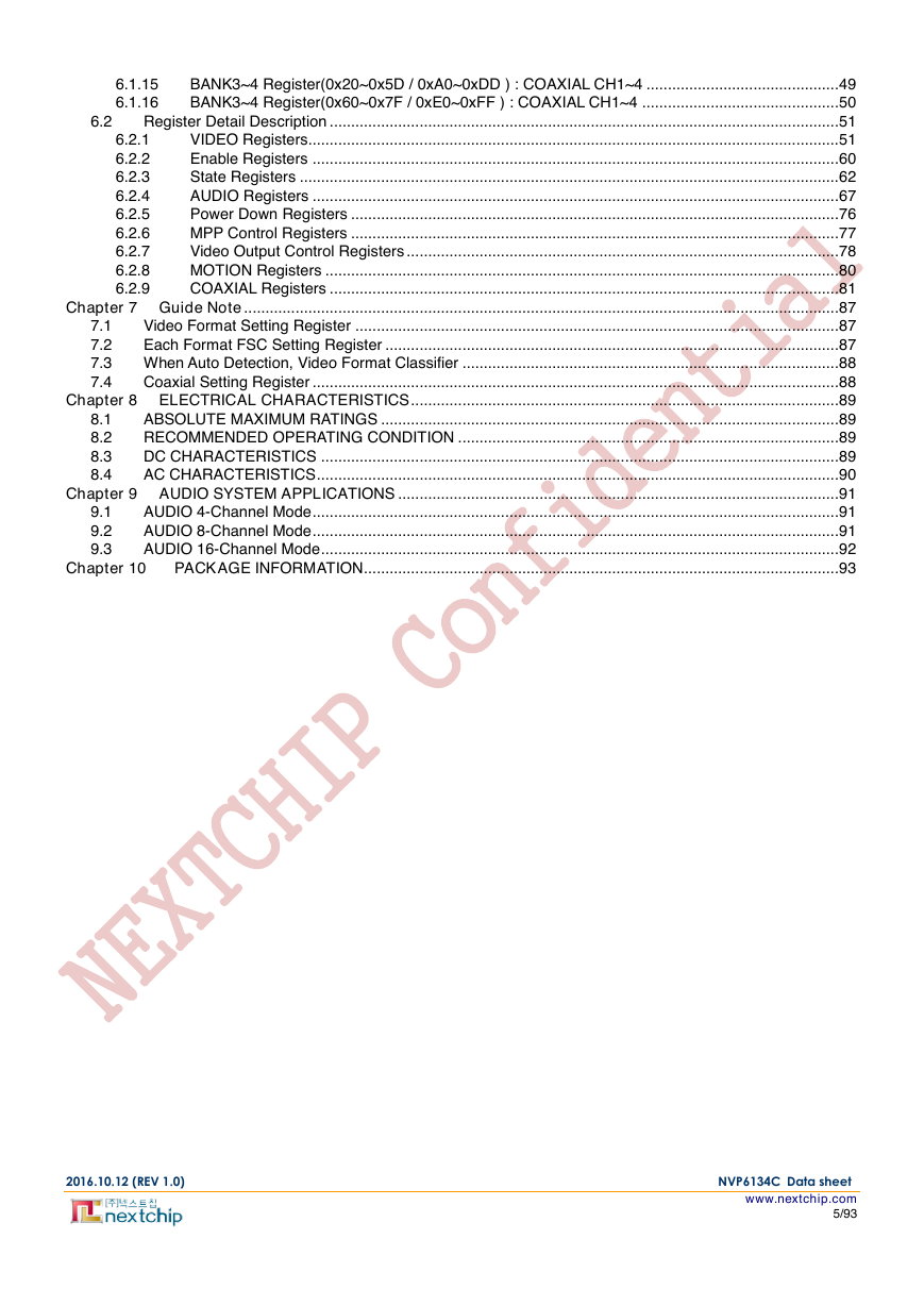
6.2
6.1.15
6.1.16
6.2.1
6.2.2
6.2.3
6.2.4
6.2.5
6.2.6
6.2.7
6.2.8
6.2.9
BANK3~4 Register(0x20~0x5D / 0xA0~0xDD ) : COAXIAL CH1~4 ............................................. 49
BANK3~4 Register(0x60~0x7F / 0xE0~0xFF ) : COAXIAL CH1~4 .............................................. 50
Register Detail Description ....................................................................................................................... 51
VIDEO Registers............................................................................................................................ 51
Enable Registers ........................................................................................................................... 60
State Registers .............................................................................................................................. 62
AUDIO Registers ........................................................................................................................... 67
Power Down Registers .................................................................................................................. 76
MPP Control Registers .................................................................................................................. 77
Video Output Control Registers ..................................................................................................... 78
MOTION Registers ........................................................................................................................ 80
COAXIAL Registers ....................................................................................................................... 81
Chapter 7 Guide Note ........................................................................................................................................... 87
Video Format Setting Register ................................................................................................................. 87
7.1
7.2
Each Format FSC Setting Register .......................................................................................................... 87
7.3 When Auto Detection, Video Format Classifier ........................................................................................ 88
Coaxial Setting Register ........................................................................................................................... 88
7.4
Chapter 8 ELECTRICAL CHARACTERISTICS .................................................................................................... 89
ABSOLUTE MAXIMUM RATINGS ........................................................................................................... 89
RECOMMENDED OPERATING CONDITION ......................................................................................... 89
DC CHARACTERISTICS ......................................................................................................................... 89
AC CHARACTERISTICS .......................................................................................................................... 90
Chapter 9 AUDIO SYSTEM APPLICATIONS ....................................................................................................... 91
AUDIO 4-Channel Mode ........................................................................................................................... 91
AUDIO 8-Channel Mode ........................................................................................................................... 91
AUDIO 16-Channel Mode ......................................................................................................................... 92
PACKAGE INFORMATION ............................................................................................................... 93
8.1
8.2
8.3
8.4
9.1
9.2
9.3
Chapter 10
2016.10.12 (REV 1.0) NVP6134C Data sheet
www.nextchip.com
5/93
�
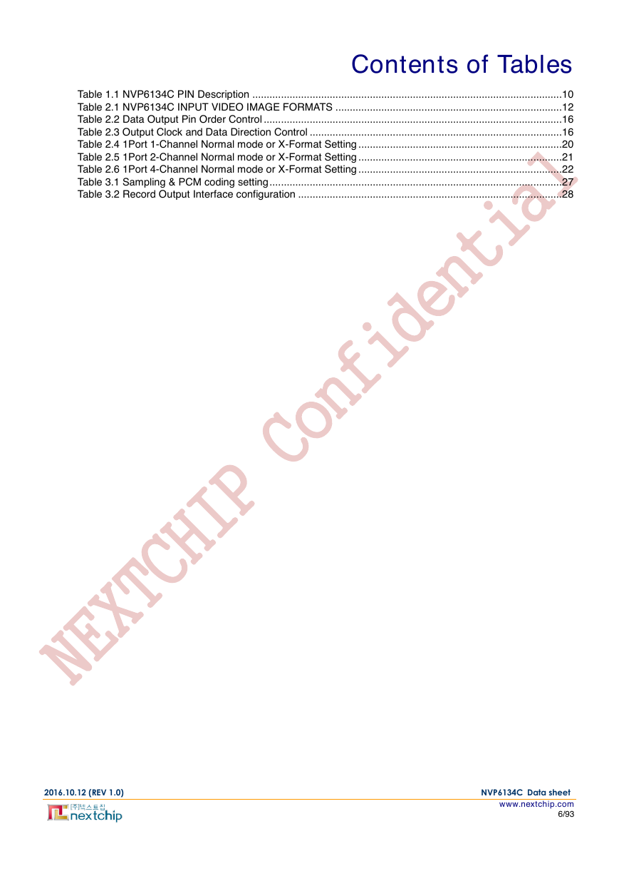
Contents of Tables
Table 1.1 NVP6134C PIN Description ............................................................................................................ 10
Table 2.1 NVP6134C INPUT VIDEO IMAGE FORMATS ............................................................................... 12
Table 2.2 Data Output Pin Order Control ........................................................................................................ 16
Table 2.3 Output Clock and Data Direction Control ........................................................................................ 16
Table 2.4 1Port 1-Channel Normal mode or X-Format Setting ....................................................................... 20
Table 2.5 1Port 2-Channel Normal mode or X-Format Setting ....................................................................... 21
Table 2.6 1Port 4-Channel Normal mode or X-Format Setting ....................................................................... 22
Table 3.1 Sampling & PCM coding setting ...................................................................................................... 27
Table 3.2 Record Output Interface configuration ............................................................................................ 28
2016.10.12 (REV 1.0) NVP6134C Data sheet
www.nextchip.com
6/93
�
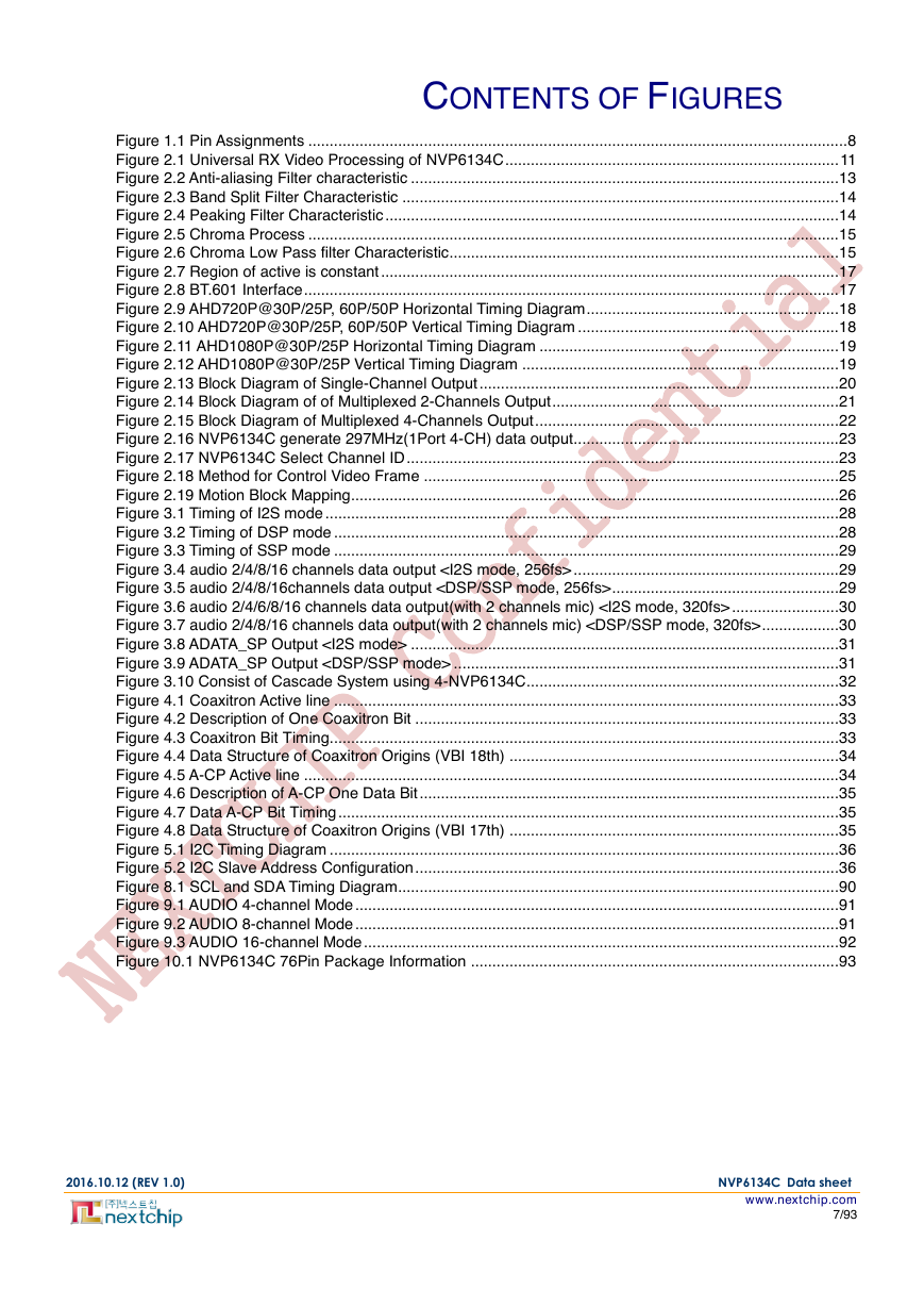
CONTENTS OF FIGURES
Figure 1.1 Pin Assignments .............................................................................................................................. 8
Figure 2.1 Universal RX Video Processing of NVP6134C .............................................................................. 11
Figure 2.2 Anti-aliasing Filter characteristic .................................................................................................... 13
Figure 2.3 Band Split Filter Characteristic ...................................................................................................... 14
Figure 2.4 Peaking Filter Characteristic .......................................................................................................... 14
Figure 2.5 Chroma Process ............................................................................................................................ 15
Figure 2.6 Chroma Low Pass filter Characteristic........................................................................................... 15
Figure 2.7 Region of active is constant ........................................................................................................... 17
Figure 2.8 BT.601 Interface ............................................................................................................................. 17
Figure 2.9 AHD720P@30P/25P, 60P/50P Horizontal Timing Diagram ........................................................... 18
Figure 2.10 AHD720P@30P/25P, 60P/50P Vertical Timing Diagram ............................................................. 18
Figure 2.11 AHD1080P@30P/25P Horizontal Timing Diagram ...................................................................... 19
Figure 2.12 AHD1080P@30P/25P Vertical Timing Diagram .......................................................................... 19
Figure 2.13 Block Diagram of Single-Channel Output .................................................................................... 20
Figure 2.14 Block Diagram of of Multiplexed 2-Channels Output ................................................................... 21
Figure 2.15 Block Diagram of Multiplexed 4-Channels Output ....................................................................... 22
Figure 2.16 NVP6134C generate 297MHz(1Port 4-CH) data output.............................................................. 23
Figure 2.17 NVP6134C Select Channel ID ..................................................................................................... 23
Figure 2.18 Method for Control Video Frame ................................................................................................. 25
Figure 2.19 Motion Block Mapping.................................................................................................................. 26
Figure 3.1 Timing of I2S mode ........................................................................................................................ 28
Figure 3.2 Timing of DSP mode ...................................................................................................................... 28
Figure 3.3 Timing of SSP mode ...................................................................................................................... 29
Figure 3.4 audio 2/4/8/16 channels data output .............................................................. 29
Figure 3.5 audio 2/4/8/16channels data output ..................................................... 29
Figure 3.6 audio 2/4/6/8/16 channels data output(with 2 channels mic) ......................... 30
Figure 3.7 audio 2/4/8/16 channels data output(with 2 channels mic) .................. 30
Figure 3.8 ADATA_SP Output .................................................................................................... 31
Figure 3.9 ADATA_SP Output .......................................................................................... 31
Figure 3.10 Consist of Cascade System using 4-NVP6134C ......................................................................... 32
Figure 4.1 Coaxitron Active line ...................................................................................................................... 33
Figure 4.2 Description of One Coaxitron Bit ................................................................................................... 33
Figure 4.3 Coaxitron Bit Timing....................................................................................................................... 33
Figure 4.4 Data Structure of Coaxitron Origins (VBI 18th) ............................................................................. 34
Figure 4.5 A-CP Active line ............................................................................................................................. 34
Figure 4.6 Description of A-CP One Data Bit .................................................................................................. 35
Figure 4.7 Data A-CP Bit Timing ..................................................................................................................... 35
Figure 4.8 Data Structure of Coaxitron Origins (VBI 17th) ............................................................................. 35
Figure 5.1 I2C Timing Diagram ....................................................................................................................... 36
Figure 5.2 I2C Slave Address Configuration ................................................................................................... 36
Figure 8.1 SCL and SDA Timing Diagram....................................................................................................... 90
Figure 9.1 AUDIO 4-channel Mode ................................................................................................................. 91
Figure 9.2 AUDIO 8-channel Mode ................................................................................................................. 91
Figure 9.3 AUDIO 16-channel Mode ............................................................................................................... 92
Figure 10.1 NVP6134C 76Pin Package Information ...................................................................................... 93
2016.10.12 (REV 1.0) NVP6134C Data sheet
www.nextchip.com
7/93
�
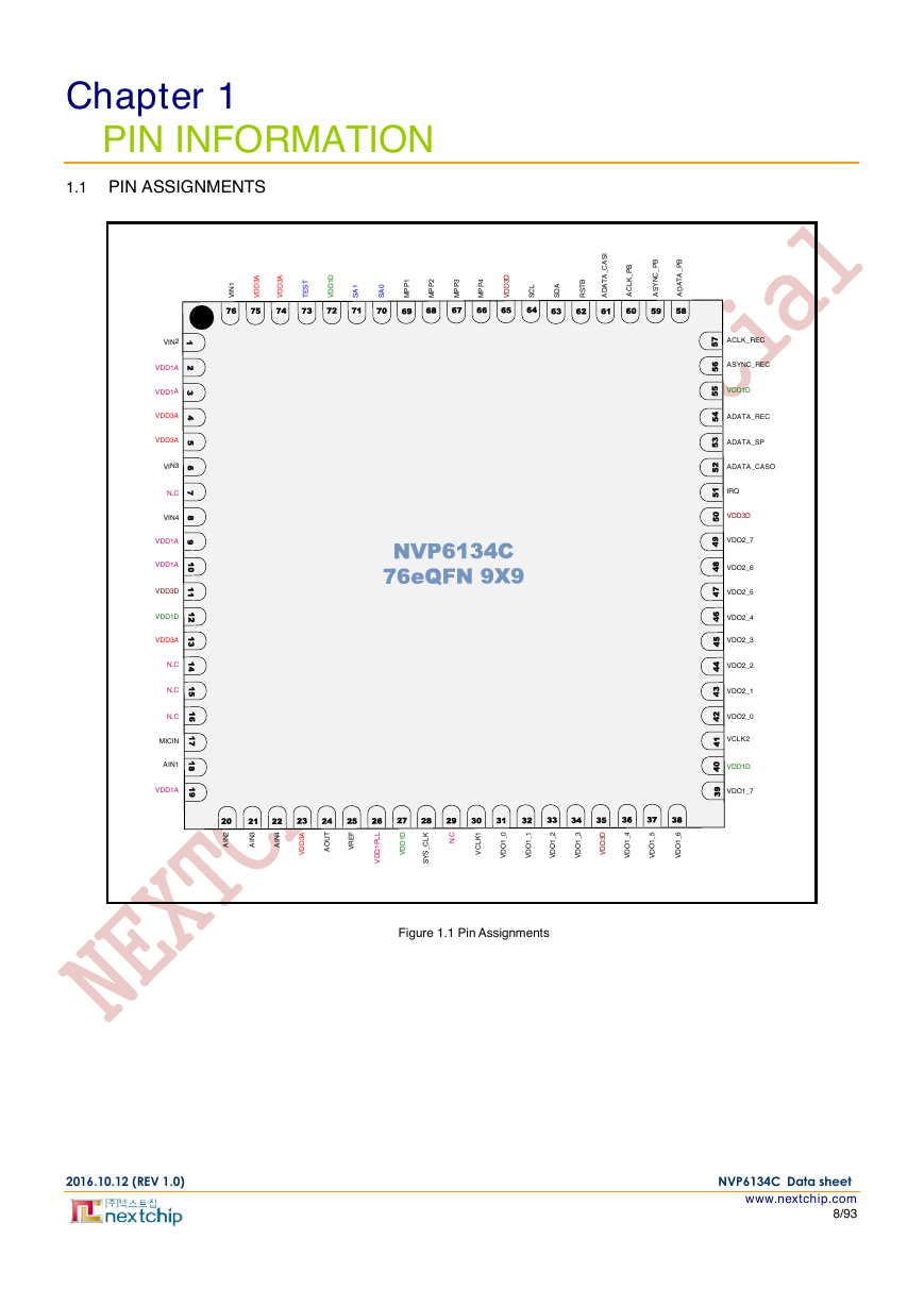
Chapter 1
PIN INFORMATION
1.1 PIN ASSIGNMENTS
Figure 1.1 Pin Assignments
2016.10.12 (REV 1.0) NVP6134C Data sheet
www.nextchip.com
8/93
SCLSDAVDD1DVDO1_7VCLK2VDO2_7VDO2_6VDD3DVDO2_5VDO2_4VDO2_3VDO2_2VDO2_1VDO2_0ACLK_RECADATA_RECASYNC_RECASYNC_PBADATA_PBACLK_PBVDD3AN.CN.CN.CMICINAIN1TESTSA1SA0RSTBADATA_CASIADATA_SPADATA_CASOIRQMPP1MPP3MPP2MPP4VDD3AVDD3ANVP6134C76eQFN 9X9123456789101112131415161718193940414243444546474849505152535455565758596061626364656667686970717273747576VDD1AVIN2VDD1AVDD3AVIN3VDD3AVDD1AN.CVIN4VDD1DVDD1DVDD1AVDD3DVDD1AVDD1DVDD3DVIN1VCLK1VDO1_6VDO1_5VDO1_4VDO1_3VDO1_2VDO1_1VDO1_0VDD1DVDD1PLLAIN2AIN3AIN4VDD3DAOUTSYS_CLKN.C20212223242526272829303132333435363738VREFVDD3A�


 2023年江西萍乡中考道德与法治真题及答案.doc
 2012年重庆南川中考生物真题及答案.doc
 2013年江西师范大学地理学综合及文艺理论基础考研真题.doc
 2020年四川甘孜小升初语文真题及答案I卷.doc
 2020年注册岩土工程师专业基础考试真题及答案.doc
 2023-2024学年福建省厦门市九年级上学期数学月考试题及答案.doc
 2021-2022学年辽宁省沈阳市大东区九年级上学期语文期末试题及答案.doc
 2022-2023学年北京东城区初三第一学期物理期末试卷及答案.doc
 2018上半年江西教师资格初中地理学科知识与教学能力真题及答案.doc
 2012年河北国家公务员申论考试真题及答案-省级.doc
 2020-2021学年江苏省扬州市江都区邵樊片九年级上学期数学第一次质量检测试题及答案.doc
 2022下半年黑龙江教师资格证中学综合素质真题及答案.doc