Lecture 220 – AC Analysis of the 741 Op Amp (2/25/02)
Page 220 - 1
LECTURE 220 – AC ANALYSIS OF THE 741 OP AMP
(READING: GHLM – 462-472)
Objective
The objective of this presentation is to:
1.) Identify the devices, circuits, and stages in the 741 operational amplifier
2.) Perform a small-signal analysis
3.) Compare hand calculations of small-signal analyses with PSpice simulations
Outline
• Small-signal analysis
• Frequency Compensation of 741
• PSpice analysis techniques and results
• Summary
ECE 6412 - Analog Integrated Circuit Design - II
Lecture 220 – AC Analysis of the 741 Op Amp (2/25/02)
© P.E. Allen - 2002
Page 220 - 2
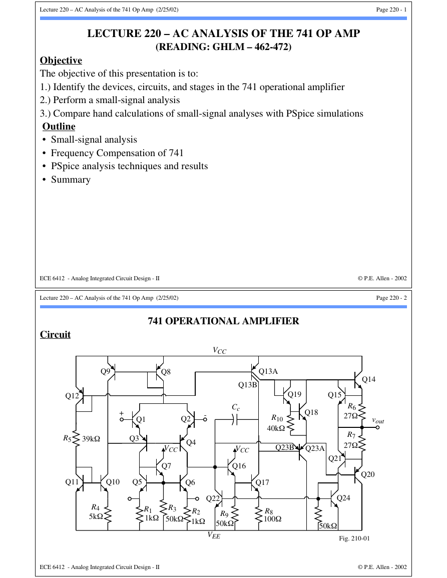
741 OPERATIONAL AMPLIFIER
Circuit
Q12
Q9
Q8
+
Q1
Q2
-
VCC
Q13A
Q13B
R5
39kΩ
Q3
Q11
Q10
Q5
VCC
Q7
Q4
Q6
R4
5kΩ
R1
1kΩ
R3
50kΩ
R2
1kΩ
Q14
vout
R6
27Ω
R7
27Ω
Q19
Q15
Q18
R10
40kΩ
Q23B
Q23A
Q21
Cc
VCC
Q16
Q17
R8
100Ω
Q22
R9
50kΩ
VEE
Q20
Q24
50kΩ
Fig. 210-01
ECE 6412 - Analog Integrated Circuit Design - II
© P.E. Allen - 2002
�
Lecture 220 – AC Analysis of the 741 Op Amp (2/25/02)
Page 220 - 3
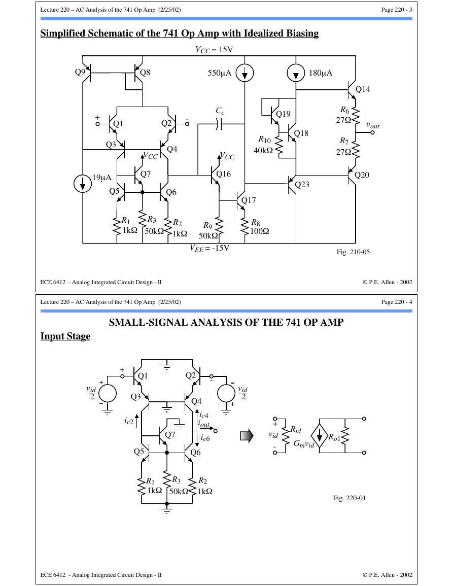
Simplified Schematic of the 741 Op Amp with Idealized Biasing
VCC = 15V
550µA
Cc
VCC
Q16
Q9
Q8
+
Q1
Q3
19µA
Q5
Q2
-
VCC
Q7
Q4
Q6
R1
1kΩ
R3
50kΩ
R2
1kΩ
R9
50kΩ
VEE = -15V
ECE 6412 - Analog Integrated Circuit Design - II
Lecture 220 – AC Analysis of the 741 Op Amp (2/25/02)
180µA
Q14
vout
R6
27Ω
R7
27Ω
Q19
Q18
R10
40kΩ
Q23
Q20
Q17
R8
100Ω
Fig. 210-05
© P.E. Allen - 2002
Page 220 - 4
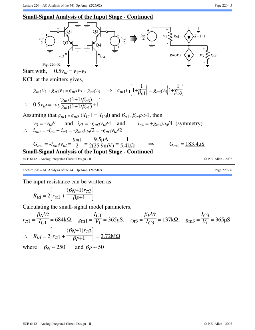
Input Stage
vid
2
SMALL-SIGNAL ANALYSIS OF THE 741 OP AMP
vid
2
+
Q1
Q3
ic2
Q5
Q2
-
Q4
ic4
iout
ic6
Q6
Q7
R1
1kΩ
R3
50kΩ
R2
1kΩ
+
vid
-
Rid
Gmvid
Ro1
Fig. 220-01
ECE 6412 - Analog Integrated Circuit Design - II
© P.E. Allen - 2002
�
Lecture 220 – AC Analysis of the 741 Op Amp (2/25/02)
Page 220 - 5
Small-Signal Analysis of the Input Stage - Continued
+
Q1
-
Q2
vid
2
Q3
ic3
Q4
ic4
Fig. 220-02
0.5vid = v1+v3
Start with,
KCL at the emitters gives,
vid
2
vid
2
+
v1
-
rπ1
gm1v1
gm3v3
+
v3
-
rπ3
gm1v1 + gπ1v1 = gm3v3 + gπ3v3 ⇒ gm1v1
1+
1
βo1 = gm3v3
1+
1
βo3
∴ 0.5vid = -v3
Assuming that gm1 = gm3 (|IC1| = |IC3|) and βo1, βo3>>1, then
gm3(1+1/βo3)
gm1(1+1/βo1) +1
v3 = -vid/4
and ic3 = -gm3vid/4
and
∴ iout = -ic4 + ic3 = -gm3vid/2 = -gm1vid/2
ic4 = +gm4vid/4 (symmetry)
gm1
2 =
9.5µA
1
Gm1 = -iout/vid =
⇒
Small-Signal Analysis of the Input Stage - Continued
ECE 6412 - Analog Integrated Circuit Design - II
2(25.9mV) =
5.4kΩ
Lecture 220 – AC Analysis of the 741 Op Amp (2/25/02)
The input resistance can be written as
Rid = 2
rπ1 +
(βN+1)rπ3
βP+1
Calculating the small-signal model parameters,
Gm1 = 183.4µS
© P.E. Allen - 2002
Page 220 - 6
IC1
Vt = 365µS, rπ3 =
βPVt
IC3 = 137kΩ, gm3 =
IC3
Vt = 365µS
rπ1 =
βNVt
IC1 = 684kΩ, gm1 =
(βN+1)rπ3
∴ Rid = 2
rπ1 +
where βN ≈ 250
βP+1
and βP ≈ 50
= 2.72MΩ
ECE 6412 - Analog Integrated Circuit Design - II
© P.E. Allen - 2002
�
Lecture 220 – AC Analysis of the 741 Op Amp (2/25/02)
Page 220 - 7
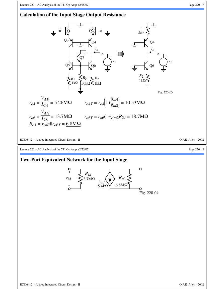
Calculation of the Input Stage Output Resistance
+
Q1
Q3
Q7
Q5
Q2
-
Q4
ix
Q6
vx
R1
1kΩ
R3
50kΩ
R2
1kΩ
1
gm2
R2
1kΩ
Q4
ix
Q6
vx
Fig. 220-03
ro4 =
= 5.26MΩ
VAP
IC4
VAN
IC6
= 13.7MΩ
ro6 =
Ro1 = ro4T||ro6T = 6.8MΩ
ro4T = ro4
gm4
gm2
1+
= 10.53MΩ
ro6T = ro6(1+gm2R2) = 18.7MΩ
ECE 6412 - Analog Integrated Circuit Design - II
Lecture 220 – AC Analysis of the 741 Op Amp (2/25/02)
Two-Port Equivalent Network for the Input Stage
© P.E. Allen - 2002
Page 220 - 8
+
vid
-
Rid
2.7MΩ
vid
5.4kΩ
Ro1
6.8MΩ
Fig. 220-04
ECE 6412 - Analog Integrated Circuit Design - II
© P.E. Allen - 2002
�
Lecture 220 – AC Analysis of the 741 Op Amp (2/25/02)
Page 220 - 9
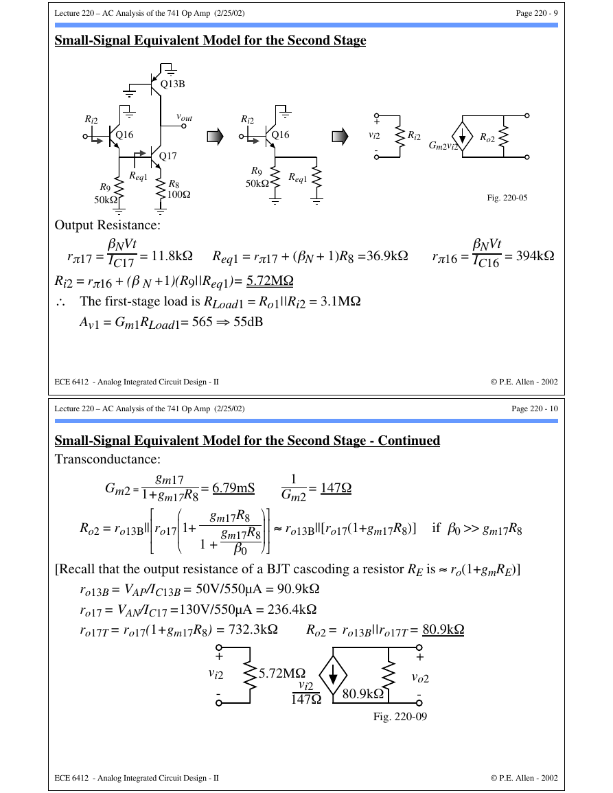
Small-Signal Equivalent Model for the Second Stage
Q13B
vout
Ri2
Ri2
Q16
Q17
R8
100Ω
Req1
R9
50kΩ
Output Resistance:
Q16
R9
50kΩ
Req1
+
vi2
-
Ri2
Gm2vi2
Ro2
Fig. 220-05
rπ17 =
βNVt
IC17 = 11.8kΩ Req1 = rπ17 + (βN + 1)R8 =36.9kΩ
rπ16 =
βNVt
IC16 = 394kΩ
Ri2 = rπ16 + (β N +1)(R9||Req1)= 5.72MΩ
∴ The first-stage load is RLoad1 = Ro1||Ri2 = 3.1MΩ
Av1 = Gm1RLoad1= 565 ⇒ 55dB
ECE 6412 - Analog Integrated Circuit Design - II
Lecture 220 – AC Analysis of the 741 Op Amp (2/25/02)
© P.E. Allen - 2002
Page 220 - 10
Small-Signal Equivalent Model for the Second Stage - Continued
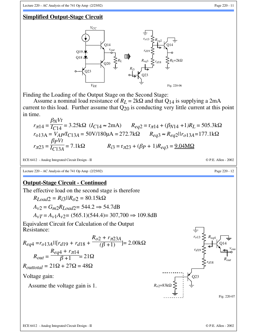
Transconductance:
gm17
Gm2 =
1+gm17R8
Ro2 = ro13B||
ro17
1+
= 6.79mS
gm17R8
gm17R8
β0
1 +
1
Gm2
= 147Ω
≈ ro13B||[ro17(1+gm17R8)]
if β0 >> gm17R8
[Recall that the output resistance of a BJT cascoding a resistor RE is ≈ ro(1+gmRE)]
ro13B = VAP/IC13B = 50V/550µA = 90.9kΩ
ro17 = VAN/IC17 =130V/550µA = 236.4kΩ
ro17T = ro17(1+gm17R8) = 732.3kΩ
Ro2 = ro13B||ro17T = 80.9kΩ
+
vi2
-
5.72MΩ
vi2
147Ω 80.9kΩ
+
vo2
-
Fig. 220-09
ECE 6412 - Analog Integrated Circuit Design - II
© P.E. Allen - 2002
�
Lecture 220 – AC Analysis of the 741 Op Amp (2/25/02)
Page 220 - 11
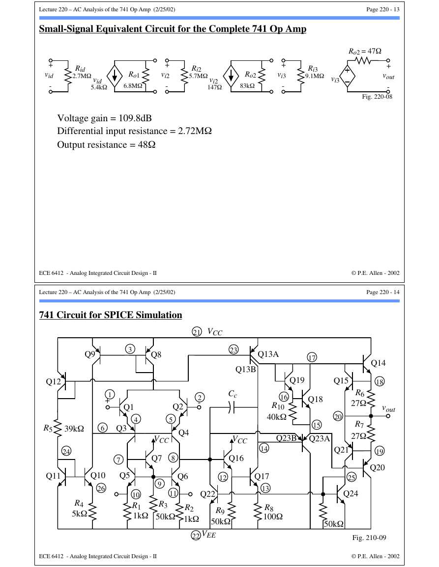
Simplified Output-Stage Circuit
Q19
Q18
VCC
Q23
VEE
Q14
vout
RL
Q20
ro13
Req2
rd19
Q14
Req3
rd18
RL=2kΩ
Ri3
Q23
Fig. 220-06
Finding the Loading of the Output Stage on the Second Stage:
Assume a nominal load resistance of RL = 2kΩ and that Q14 is supplying a 2mA
current to this load. Further assume that Q20 is conducting very little current at this point
in time.
βNVt
IC14 = 3.25kΩ (IC14 ≈ 2mA)
rπ14 =
ro13A = VAP/IC13A = 50V/180µA = 272.7kΩ
Req2 = rπ14 + (βN14 +1)RL = 505.3kΩ
Req3 ≈ Req2||ro13A=177.1kΩ
rπ23 =
βPVt
IC13A = 7.1kΩ
Ri3 = rπ23 + (βP + 1)Req3 = 9.04MΩ
ECE 6412 - Analog Integrated Circuit Design - II
Lecture 220 – AC Analysis of the 741 Op Amp (2/25/02)
© P.E. Allen - 2002
Page 220 - 12
Output-Stage Circuit - Continued
The effective load on the second stage is therefore
RLoad2 = Ri3||Ro2 = 80.15kΩ
Av2 = Gm2RLoad2= 544.2 ⇒ 54.7dB
AvT = Av1Av2= (565.1)(544.4)= 307,700 ⇒ 109.8dB
Equivalent Circuit for Calculation of the Output
Resistance:
Ro2 + rπ23A
(β +1)
]= 2.00kΩ
Req4 =ro13A||[rd19 + rd18 +
Req4 + rπ14
β +1
Rout =
= 21Ω
Routtotal = 21Ω + 27Ω = 48Ω
Voltage gain:
Assume the voltage gain is 1.
Ro2=83kΩ
ro13
Req4
Q14
vout
rd18
Rout
rd19
Q23
Fig. 220-07
ECE 6412 - Analog Integrated Circuit Design - II
© P.E. Allen - 2002
�
Lecture 220 – AC Analysis of the 741 Op Amp (2/25/02)
Page 220 - 13
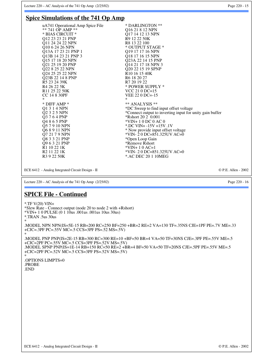
Small-Signal Equivalent Circuit for the Complete 741 Op Amp
+
vid
-
Rid
2.7MΩ
vid
5.4kΩ
Ro1
6.8MΩ
+
vi2
-
Ri2
5.7MΩ
vi2
147Ω
Ro2
83kΩ
+
vi3
-
Ri3
9.1MΩ vi3
Ro2 = 47Ω
+
vout
-
Fig. 220-08
Voltage gain = 109.8dB
Differential input resistance = 2.72MΩ
Output resistance = 48Ω
ECE 6412 - Analog Integrated Circuit Design - II
Lecture 220 – AC Analysis of the 741 Op Amp (2/25/02)
741 Circuit for SPICE Simulation
21
VCC
Q9
3
Q8
Q12
1
+
Q1
4
Q3
R5
39kΩ
6
24
Q11
7
Q5
Q10
26
R4
5kΩ
ECE 6412 - Analog Integrated Circuit Design - II
23
Q13A
Q13B
17
Q19
Q15
Q2
5
Q4
VCC
Q7
8
Cc
2
-
VCC
Q16
16
R10
40kΩ
Q23B
Q18
15
Q23A
14
Q17
13
R8
100Ω
9
11
R3
50kΩ
10
R1
1kΩ
Q6
12
Q22
R2
1kΩ
R9
50kΩ
VEE
22
© P.E. Allen - 2002
Page 220 - 14
Q14
18
vout
19
Q20
R6
27Ω
R7
27Ω
20
Q21
25
Q24
50kΩ
Fig. 210-09
© P.E. Allen - 2002
�
Lecture 220 – AC Analysis of the 741 Op Amp (2/25/02)
Page 220 - 15
Spice Simulations of the 741 Op Amp
uA741 Operational Amp Spice File
** 741 OP AMP **
* BIAS CIRCUIT *
Q12 23 23 21 PNP
Q11 24 24 22 NPN
Q10 6 24 26 NPN
Q13A 17 23 21 PNP 1
Q13B 14 23 21 PNP 3
Q15 17 18 20 NPN
Q21 25 19 20 PNP
Q22 8 25 22 NPN
Q24 25 25 22 NPN
Q23B 22 14 8 PNP
R5 23 24 39K
R4 26 22 5K
R11 25 22 50K
CC 14 8 30PF
*
* DIFF AMP *
Q1 3 1 4 NPN
Q2 3 2 5 NPN
Q3 7 6 4 PNP
Q4 8 6 5 PNP
Q5 7 9 10 NPN
Q6 8 9 11 NPN
Q7 21 7 9 NPN
Q8 3 3 21 PNP
Q9 6 3 21 PNP
R1 10 22 1K
R2 11 22 1K
R3 9 22 50K
* DARLINGTON **
Q16 21 8 12 NPN
Q17 14 12 13 NPN
R9 12 22 50K
R8 13 22 100
* OUTPUT STAGE *
Q19 17 17 16 NPN
Q18 17 16 15 NPN
Q23A 22 14 15 PNP
Q14 21 17 18 NPN 3
Q20 22 15 19 SPNP
R10 16 15 40K
R6 18 20 27
R7 20 19 22
* POWER SUPPLY *
VCC 21 0 DC=15
VEE 22 0 DC=-15
*
** ANALYSIS **
*DC Sweep to find input offset voltage
*Connect output to inverting input for unity gain buffer
*Rshort 20 2 0.001
*VIN+ 1 0 DC 0 AC 0
*.DC VIN+ -15V +15V .1V
* Now provide input offset voltage
*VIN- 2 0 DC=851.325UV AC=0
*Open Loop Gain
*Remove Rshort
*VIN+ 1 0 AC=1
*VIN- 2 0 DC=851.325UV AC=0
*.AC DEC 20 1 10MEG
ECE 6412 - Analog Integrated Circuit Design - II
Lecture 220 – AC Analysis of the 741 Op Amp (2/25/02)
© P.E. Allen - 2002
Page 220 - 16
SPICE File - Continued
*.TF V(20) VIN+
*Slew Rate - Connect output (node 20 to node 2 with +Rshort)
*VIN+ 1 0 PULSE (0 1 10us .001us .001us 10us 30us)
*.TRAN .5us 30us
*
.MODEL NPN NPN(IS=5E-15 RB=200 RC=250 BF=250 +BR=2 RE=2 VA=130 TF=.35NS CJE=1PF PE=.7V ME=.33
+CJC=.3PF PC=.55V MC=.5 CCS=3PF PS=.52 MS=.5V)
*
.MODEL PNP PNP(IS=2E-15 RB=300 RC=300 RE=10 +BF=50 BR=4 VA=50 TF=30NS CJE=.3PF PE=.55V ME=.5
+CJC=2PF PC=.55V MC=.5 CCS=3PF PS=.52V MS=.5V)
.MODEL SPNP PNP(IS=1E-14 RB=150 RC=50 RE=2 +BR=4 BF=50 VA=50 TF=20NS CJE=.5PF PE=.55V ME=.5
+CJC=2PF PC=.52V MC=.5 CCS=3PF PS=.52V MS=.5V)
*
.OPTIONS LIMPTS=0
.PROBE
.END
ECE 6412 - Analog Integrated Circuit Design - II
© P.E. Allen - 2002
�


 2023年江西萍乡中考道德与法治真题及答案.doc
 2012年重庆南川中考生物真题及答案.doc
 2013年江西师范大学地理学综合及文艺理论基础考研真题.doc
 2020年四川甘孜小升初语文真题及答案I卷.doc
 2020年注册岩土工程师专业基础考试真题及答案.doc
 2023-2024学年福建省厦门市九年级上学期数学月考试题及答案.doc
 2021-2022学年辽宁省沈阳市大东区九年级上学期语文期末试题及答案.doc
 2022-2023学年北京东城区初三第一学期物理期末试卷及答案.doc
 2018上半年江西教师资格初中地理学科知识与教学能力真题及答案.doc
 2012年河北国家公务员申论考试真题及答案-省级.doc
 2020-2021学年江苏省扬州市江都区邵樊片九年级上学期数学第一次质量检测试题及答案.doc
 2022下半年黑龙江教师资格证中学综合素质真题及答案.doc