Published SFF-8636 Rev 2.7
SFF Committee documentation may be purchased in electronic form.
SFF specifications are available at ftp://ftp.seagate.com/sff
SFF Committee
SFF-8636
Specification for
Management Interface for Cabled Environments
Rev 2.7 January 26, 2016
Secretariat: SFF Committee
Abstract: This specification defines a common management interface for 4-lane
pluggable transceiver modules, direct attach modules and shielded cable assemblies.
Physical layer and mechanical details of the connector interface are outside the
scope of this document.
This specification provides a common reference for systems manufacturers, system
integrators, and suppliers. This is an internal working specification of the SFF
Committee, an industry ad hoc group.
This specification is made available for public review, and written comments are
solicited from readers. Comments received by the members will be considered for
inclusion in future revisions of this specification.
Support: This specification is supported by the identified member companies of the
SFF Committee.
POINTS OF CONTACT:
Barry Olawsky Tom Palkert I. Dal Allan
Hewlett Packard Molex Chairman SFF Committee
11445 Compaq Center Dr W 2222 Wellington Ct 14426 Black Walnut Court
Houston, TX 77070 Lisle, IL 60532 Saratoga CA 95070
Ph: 281-514-8624 Ph: 952-200-8542 Ph: 408-867-6630
barry.olawsky@hp.com tpalkert@molex.com endlcom@acm.org
Management Interface for Cabled Environments Page 1
�
Published SFF-8636 Rev 2.7
EXPRESSION OF SUPPORT BY MANUFACTURERS
The following member companies of the SFF Committee voted in favor of this industry
specification.
Amphenol
LSI
Arista Networks
Lumentum
Dell Computer
Luxshare-ICT
ENDL
ETRI
FCI
Finisar
Foxconn
Mellanox
Molex
NetApp
QLogic
Seagate
GLGnet Electronics
Shinning Electronics
Hewlett Packard
IBM
Jess-Link
Siemon
Sumitomo
TE Connectivity
The following member companies of the SFF Committee voted to abstain on this
industry specification.
AMI
Avago
Broadcom
Cinch
EMC
Emulex
HGST
Intel
Oclaro
Pioneer
Sandisk
Sun Microsystems
Toshiba
Volex
Western Digital
Yamaichi
The user's attention is called to the possibility that implementation to this
Specification may require use of an invention covered by patent rights. By
distribution of this specification, no position is taken with respect to the
validity of a claim or claims or of any patent rights in connection therewith.
Members of the SFF Committee which advise that a patent exists are required to
provide a statement of willingness to grant a license under these rights on
reasonable and non-discriminatory terms and conditions to applicants desiring to
obtain such a license.
Update History:
Rev 0.9
- Clarified wording in 6.2.2
Rev 1.0
- Added missing reservation entries (Bytes 133, 134, and 220). Modified bit entry
labels (Bytes 93 and 136).
Rev 1.2
- Editorial: Formatted Word controls to improve pagination breaks and comply with
style guide.
Rev 1.3
- Table 20 Identifier Values and Table 24 Encoding Values modified to point to SFF-
8024 as the reference for later values and codes.
Rev 1.4
- Added Revision Compliance Byte. Changed Bytes 1, 131, 138, 146, 164, 188, and 189
to comply with latest SFF-8436 map. Added 12 Gb/s SAS bit in Byte 133. Various
grammatical changes made.
Rev 1.5
- Added functionality for QSFP28 (4x25G, 4x28G) transceivers per the requirements
of 100GE, EDR Infiniband and 128GFC Fibre Channel. Tables 7, 8, 10, 12, 13, 17, 19,
Management Interface for Cabled Environments Page 2
�
Published SFF-8636 Rev 2.7
20, 21, 23, 29, 29A, 32A, 36, 37, 41 and section 6.2.5, 6.3.6, 6.3.12, 6.3.27.
Rev 1.6
- Abstract and Scope corrected to include transceiver modules as well as shielded
cables as intended applications.
Rev 1.7
- Editorial: Expanded 2.1 to include specifications referenced in the body. Near-
invisible superscripts were modified to be visible text and cross-references made
dynamic.
- Reference to SFF-8078 in Table 13 Control Function Bytes corrected to SFF-8079.
- Table 20 Identifier Values and Table 24 Encoding Values which had been retained
in the text for information were removed.
- Table 23 Specification Compliance and Table 29A Extended Ethernet Compliance
Codes tables were moved to SFF-8024.
Rev 1.9
- Clarified Address 5 Loss of Lock indicators as latched
- Added Address 93 bit 2 High Power Class Enable lockout feature
- Clarified Address 98 CDR controls as 1b=On and 0b=Off (ie. bypassed)
- Clarified Table 21 for Address 129 bits 1-0 to refer to Address 93 bit 2
- Added Adaptive EQ indicator in Address 193 bit 3.
- Clarified Address 194 bits 7-6 setting as 1b=Controllable, 0b=Fixed
- Added Address 220 bit 2 to identify Tx Power diagnostic monitoring supported
- Added Page 03h Address 224 to define magnitude of Tx EQ and Rx Emph supported
- Added TX Adaptive EQ capability indicator, Page 00h, Address 193 bit 3
- Added TX Adaptive EQ (per ch) control bits in Page 03h, Address 241 bits 3-0
- Added TX Adaptive EQ Fault flag in Address 6 and masking bits in Address 101
- Added RX output amplitude support indicators in Page 03h Byte 225
- Added text to section 6.3.2 indicating that the power class identifiers specify
worst case maximum power dissipation.
- Added Initialization complete flag to Byte 6 bit 0.
Rev 2.0
- Changed the amplitude setting 0 from 200-400 to 100-400mv.
- Added Version 2 to address 141.
- Added Version 2 Rate Select table to Table 14 with: 00 as under 12 Gb/s, 01 as
between 12 Gb/s and 24 Gb/s, 10 as between 24 Gb/s and 26 Gb/s and 11 is above 26
Gb/s
- Changed revision register compliance bit for revision 1.9 to 2.0 (1.9 was never
released)
- Editorial changes to fix spelling and maintain consistent naming.
Rev 2.1
- Assigned Page 00h Bytes 111-112 for use by PCI-SIG
- Restored Table 23 and Table 24 from SFF-8024
- Replaced 'See SFF-8024 Table 4-x' with 'See SFF-8024 Transceiver Management'
- Made Page/Address Byte, Page/Address, Page/Byte synonyms common: as Page/Byte
- Added Page/Byte/Bit location to those table titles which did not have it
- Alphabetized abbreviations and added some that were missing
- Deleted 'Ethernet' in respect to Extended Specification Compliance Codes
- Replaced Figure 13 with current use of memory
- Other minor corrections e.g. added 'h' as in Page 00h when it was missing
Rev 2.2
- During the review of Rev 2.1 it was recommended that:
o the contents of Table 22 Connector Type be moved to SFF-8024.
o the contents of Table 24 Encoding Values be returned to SFF-8024.
- Other minor editing improvements
Rev 2.3
- Nomenclature of 10e in Section 2.5 Abbreviations replaced by 10^
Rev 2.4
- Adopted Figure/Table numbering style of current template
- To make correlation of previous Change History easier for readers, a Cross
Reference of Figures and Tables was prepared.
Management Interface for Cabled Environments Page 3
�
Published SFF-8636 Rev 2.7
Rev 2.5
- Table 6-30 split creating new Table 6-31. Old Tables 6-31 to 6-35 become new
Tables 6-32 to 6-36.
- Figure 1-1 updated to reference SFF-8665 (QSFP28)
- 2.1 Industry Documents - added SFF-8665
- Table 5-3 updated to include Bytes 93, 98, 99 and 107
- Table 5-6 updated to include sub-headings with page numbers and to add Bytes 94-
97, 100-104, 105-106, 111-112, 114-118. Changed description of Page 03h Bytes
226-241 to Optional Channel Controls. Added Page 03h Bytes 254-255.
- 6.1 Overview. Added fourth paragraph explaining details of non-implemented
pages.
- Figure 6-1. Updated Page 00h descriptions for Bytes 22-33, 100-104, 105-106,
108-110, 111-112, 113 and 114. Removed '(Cable Assemblies)' from Page 03h sub-
heading.
- 6.1.1.1 shortened column descriptions by removing 'applications' from each one.
- Table 6-1. Updated descriptions at Bytes 22-33, 86-98, 99, 100-104, 105-106,
108-110, 111-112, 113, 114-118.
- 6.2.2 Status Indicators. Added text to third sentence of first paragraph to
emphasize that both the IntL pin and bit are asserted upon completion of a power
up reset.
- Table 6-3. Added value 07h for rev 2.5. Added text to value 00h - 'Do not use
for...'. Updated value 01h to say SFF-8436 rev 4.8 or earlier.
- Table 6-5. Additional description for Byte 6 bit 0 Initialization Complete Flag
referencing Table 6-25 for the new Initialization Complete Implemented bit.
- 6.2.4 Free Side Device Monitors. Added fifthh paragraph to explain placement of
temperature sensor.
- Table 6-8. Added Bytes 66-73 description for reserved channel monitor set 5.
- Table 6-13. Corrected Byte 101 bits 7-4 names from L-Tx… to M-Tx…
- 6.2.9 Free Side Device Properties. Added paragraphs 5 and 6 to explain the
purpose of Byte 113 bits 3-0 and Byte 113 bits 6-4. This byte is added for
breakout cables.
- Table 6-14. Added Byte 113 bits 6-4 Far End Implementation and bits 3-0 Near End
Implementation descriptions.
- 6.2.11 Page Select. Added last sentence to define behavior when the host writes
an unsupported page value.
- Table 6-15. Removed sub-headers for Base ID, Extended ID and Vendor Specific ID
Fields. Changed Name of Byte 130 from 'Connector, Media' to 'Connector Type'.
Updated description of Byte 146 to clarify that all cable assemblies are in
units of 1m and OM4 fiber lengths are in units of 2m.
- 6.3.8 through 6.3.12. Added words to clarify usage for separable modules and for
cable assemblies.
- 6.3.13. Additional sentence referencing Byte 130 (connector type) to distinguish
active optical cable (AOC) from separable module (SM).
- Table 6-20. Added '/ Undefined' to value 1000b.
- 6.3.27 Diagnostic Monitoring Type. Added additional words to fourth and fifth
paragraphs to explain the treatment of Byte 220 bits 3-2 when not set.
- Table 6-25. Added Byte 221 bit 4 Initialization Complete Flag Implemented, with
explanation.
- Table 6-29. Reformatted with # Bytes column and updated descriptions.
- Table 6-31. Added Byte 225 bits 5-4 Rx output emphasis type with description.
- Table 6-32. Bytes 226-233 from Vendor Specific to Reserved. Added descriptions
for Byte 241 bits 3-0 to specify that adaptive equalization is the default if it
is implemented.
- Table 6-35. Code 1xxx from Vendor Specific to Reserved.
- 6.6.2 Optional Channel Controls. Added 2 sentences at the end of first paragraph
to explain that free side devices can limit the maximum emphasis supported using
Byte 224.
Management Interface for Cabled Environments Page 4
�
Published SFF-8636 Rev 2.7
Rev 2.6
- Title changed per request to comply with the lexicon
- Table 5-4 and other content consolidated into Table 5-3.
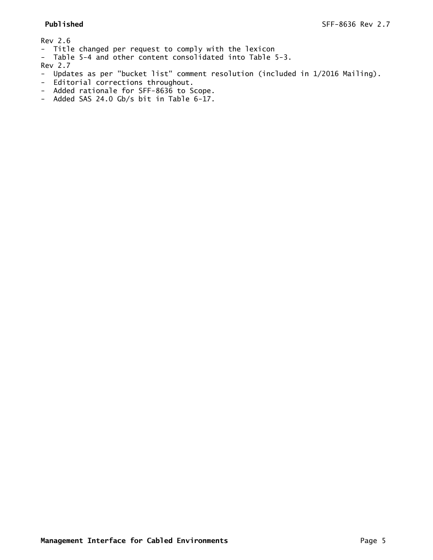
Rev 2.7
- Updates as per "bucket list" comment resolution (included in 1/2016 Mailing).
- Editorial corrections throughout.
- Added rationale for SFF-8636 to Scope.
- Added SAS 24.0 Gb/s bit in Table 6-17.
Management Interface for Cabled Environments Page 5
�
Published SFF-8636 Rev 2.7
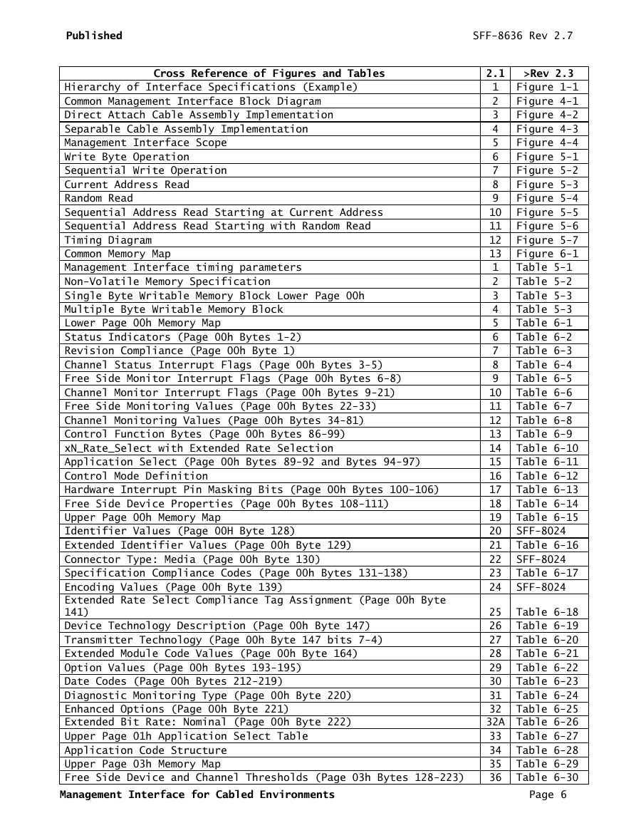
Cross Reference of Figures and Tables
2.1
>Rev 2.3
Hierarchy of Interface Specifications (Example) 1 Figure 1-1
Common Management Interface Block Diagram 2 Figure 4-1
Direct Attach Cable Assembly Implementation 3 Figure 4-2
Separable Cable Assembly Implementation 4 Figure 4-3
Management Interface Scope 5 Figure 4-4
Write Byte Operation 6 Figure 5-1
Sequential Write Operation 7 Figure 5-2
Current Address Read 8 Figure 5-3
Random Read 9 Figure 5-4
Sequential Address Read Starting at Current Address 10 Figure 5-5
Sequential Address Read Starting with Random Read 11 Figure 5-6
Timing Diagram 12 Figure 5-7
Common Memory Map 13 Figure 6-1
Management Interface timing parameters 1 Table 5-1
Non-Volatile Memory Specification 2 Table 5-2
Single Byte Writable Memory Block Lower Page 00h 3 Table 5-3
Multiple Byte Writable Memory Block 4 Table 5-3
Lower Page 00h Memory Map 5 Table 6-1
Status Indicators (Page 00h Bytes 1-2) 6 Table 6-2
Revision Compliance (Page 00h Byte 1) 7 Table 6-3
Channel Status Interrupt Flags (Page 00h Bytes 3-5) 8 Table 6-4
Free Side Monitor Interrupt Flags (Page 00h Bytes 6-8) 9 Table 6-5
Channel Monitor Interrupt Flags (Page 00h Bytes 9-21) 10 Table 6-6
Free Side Monitoring Values (Page 00h Bytes 22-33) 11 Table 6-7
Channel Monitoring Values (Page 00h Bytes 34-81) 12 Table 6-8
Control Function Bytes (Page 00h Bytes 86-99) 13 Table 6-9
xN_Rate_Select with Extended Rate Selection 14 Table 6-10
Application Select (Page 00h Bytes 89-92 and Bytes 94-97) 15 Table 6-11
Control Mode Definition 16 Table 6-12
Hardware Interrupt Pin Masking Bits (Page 00h Bytes 100-106) 17 Table 6-13
Free Side Device Properties (Page 00h Bytes 108-111) 18 Table 6-14
Upper Page 00h Memory Map 19 Table 6-15
Identifier Values (Page 00H Byte 128) 20 SFF-8024
Extended Identifier Values (Page 00h Byte 129) 21 Table 6-16
Connector Type: Media (Page 00h Byte 130) 22 SFF-8024
Specification Compliance Codes (Page 00h Bytes 131-138) 23 Table 6-17
Encoding Values (Page 00h Byte 139) 24 SFF-8024
Extended Rate Select Compliance Tag Assignment (Page 00h Byte
141)
25 Table 6-18
Device Technology Description (Page 00h Byte 147) 26 Table 6-19
Transmitter Technology (Page 00h Byte 147 bits 7-4) 27 Table 6-20
Extended Module Code Values (Page 00h Byte 164) 28 Table 6-21
Option Values (Page 00h Bytes 193-195) 29 Table 6-22
Date Codes (Page 00h Bytes 212-219) 30 Table 6-23
Diagnostic Monitoring Type (Page 00h Byte 220) 31 Table 6-24
Enhanced Options (Page 00h Byte 221) 32 Table 6-25
Extended Bit Rate: Nominal (Page 00h Byte 222) 32A Table 6-26
Upper Page 01h Application Select Table 33 Table 6-27
Application Code Structure 34 Table 6-28
Upper Page 03h Memory Map 35 Table 6-29
Free Side Device and Channel Thresholds (Page 03h Bytes 128-223) 36 Table 6-30
Management Interface for Cabled Environments Page 6
�
Published SFF-8636 Rev 2.7
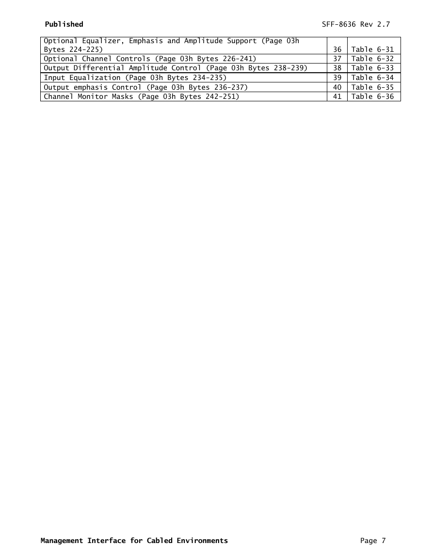
Optional Equalizer, Emphasis and Amplitude Support (Page 03h
Bytes 224-225)
36 Table 6-31
Optional Channel Controls (Page 03h Bytes 226-241) 37 Table 6-32
Output Differential Amplitude Control (Page 03h Bytes 238-239) 38 Table 6-33
Input Equalization (Page 03h Bytes 234-235) 39 Table 6-34
Output emphasis Control (Page 03h Bytes 236-237) 40 Table 6-35
Channel Monitor Masks (Page 03h Bytes 242-251) 41 Table 6-36
Management Interface for Cabled Environments Page 7
�
Published SFF-8636 Rev 2.7
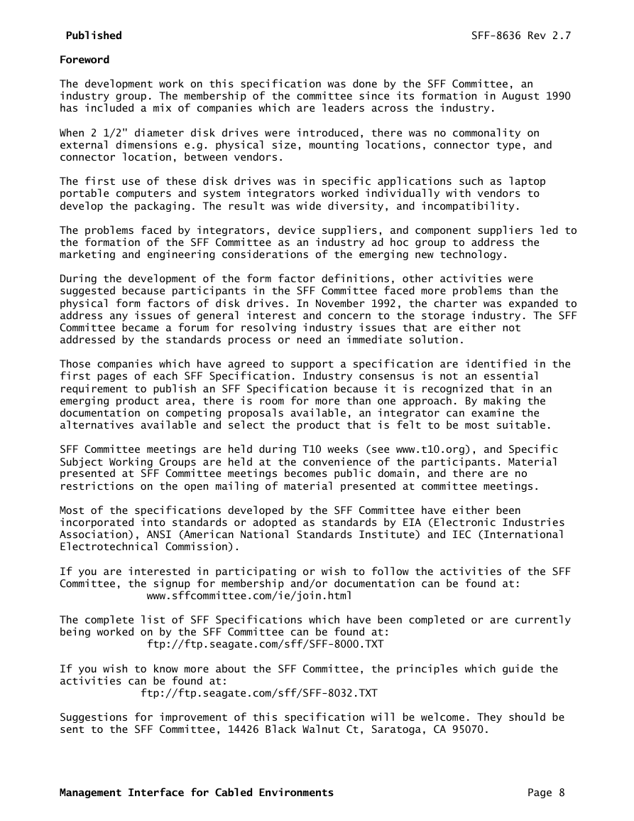
Foreword
The development work on this specification was done by the SFF Committee, an
industry group. The membership of the committee since its formation in August 1990
has included a mix of companies which are leaders across the industry.
When 2 1/2" diameter disk drives were introduced, there was no commonality on
external dimensions e.g. physical size, mounting locations, connector type, and
connector location, between vendors.
The first use of these disk drives was in specific applications such as laptop
portable computers and system integrators worked individually with vendors to
develop the packaging. The result was wide diversity, and incompatibility.
The problems faced by integrators, device suppliers, and component suppliers led to
the formation of the SFF Committee as an industry ad hoc group to address the
marketing and engineering considerations of the emerging new technology.
During the development of the form factor definitions, other activities were
suggested because participants in the SFF Committee faced more problems than the
physical form factors of disk drives. In November 1992, the charter was expanded to
address any issues of general interest and concern to the storage industry. The SFF
Committee became a forum for resolving industry issues that are either not
addressed by the standards process or need an immediate solution.
Those companies which have agreed to support a specification are identified in the
first pages of each SFF Specification. Industry consensus is not an essential
requirement to publish an SFF Specification because it is recognized that in an
emerging product area, there is room for more than one approach. By making the
documentation on competing proposals available, an integrator can examine the
alternatives available and select the product that is felt to be most suitable.
SFF Committee meetings are held during T10 weeks (see www.t10.org), and Specific
Subject Working Groups are held at the convenience of the participants. Material
presented at SFF Committee meetings becomes public domain, and there are no
restrictions on the open mailing of material presented at committee meetings.
Most of the specifications developed by the SFF Committee have either been
incorporated into standards or adopted as standards by EIA (Electronic Industries
Association), ANSI (American National Standards Institute) and IEC (International
Electrotechnical Commission).
If you are interested in participating or wish to follow the activities of the SFF
Committee, the signup for membership and/or documentation can be found at:
www.sffcommittee.com/ie/join.html
The complete list of SFF Specifications which have been completed or are currently
being worked on by the SFF Committee can be found at:
ftp://ftp.seagate.com/sff/SFF-8000.TXT
If you wish to know more about the SFF Committee, the principles which guide the
activities can be found at:
ftp://ftp.seagate.com/sff/SFF-8032.TXT
Suggestions for improvement of this specification will be welcome. They should be
sent to the SFF Committee, 14426 Black Walnut Ct, Saratoga, CA 95070.
Management Interface for Cabled Environments Page 8
�


 2023年江西萍乡中考道德与法治真题及答案.doc
 2012年重庆南川中考生物真题及答案.doc
 2013年江西师范大学地理学综合及文艺理论基础考研真题.doc
 2020年四川甘孜小升初语文真题及答案I卷.doc
 2020年注册岩土工程师专业基础考试真题及答案.doc
 2023-2024学年福建省厦门市九年级上学期数学月考试题及答案.doc
 2021-2022学年辽宁省沈阳市大东区九年级上学期语文期末试题及答案.doc
 2022-2023学年北京东城区初三第一学期物理期末试卷及答案.doc
 2018上半年江西教师资格初中地理学科知识与教学能力真题及答案.doc
 2012年河北国家公务员申论考试真题及答案-省级.doc
 2020-2021学年江苏省扬州市江都区邵樊片九年级上学期数学第一次质量检测试题及答案.doc
 2022下半年黑龙江教师资格证中学综合素质真题及答案.doc