logo资料库

PCap官方数据手册.pdf

第1页 / 共182页
第2页 / 共182页
第3页 / 共182页
第4页 / 共182页
第5页 / 共182页
第6页 / 共182页
第7页 / 共182页
第8页 / 共182页
资料共182页,剩余部分请下载后查看
General Description
Key Benefits & Features
Applications MEMS Sensors
Block Diagram
Pin Assignments
Pin Description
Pad Coordinates
Absolute Maximum Ratings
Electrical Characteristics
CDC Characteristics
RDC Characteristics
Timing Characteristics
Detailed Description
Register Description
Configuration Registers
Register Overview
Detailed Configuration Register Description
Configuration Register 0 (Address 0x0)
Configuration Register 1 (Address 0x1)
Configuration Register 2 (Address 0x2)
Configuration Register 3 (Address 0x3)
Configuration Register 4 (Address 0x4)
Configuration Register 5 (Address 0x5)
Configuration Register 6 (Address 0x6)
Configuration Register 7:8 (Address 0x7, 0x8)
Configuration Register 11:9 (Address 0x9;0xA;0xB)
Configuration Register 12 (Address 0xC)
Configuration Register 13 (Address 0xD)
Configuration Register 14 (Address 0xE)
Configuration Register 15 (Address 0xF)
Configuration Register 16 (Address 0x10)
Configuration Register 17 (Address 0x11)
Configuration Register 18 (Address 0x12)
Configuration Register 19 (Address 0x13)
Configuration Register 20 (Address 0x14)
Configuration Register 21 (Address 0x15)
Configuration Register 22(Address 0x16)
Configuration Register 23 (Address 0x17)
Configuration Register 24 (Address 0x18)
Configuration Register 25 (Address 0x19)
Configuration Register 26 (Address 0x1A)
Configuration Register 27 (Address 0x1B)
Configuration Register 28 (Address 0x1C)
Configuration Register 29 (Address 0x1D)
Configuration Register 30 (Address 0x1E)
Configuration Register 31 (Address 0x1F)
Configuration Register 32 (Address 0x20)
Configuration Register 33 (Address 0x21)
Configuration Register 34 (Address 0x22)
Configuration Register 35 (Address 0x23)
Configuration Register 36 (Address 0x24)
Configuration Register 37 (Address 0x25)
Configuration Register 38 (Address 0x26)
Configuration Register 39 (Address 0x27)
Configuration Register 40 (Address 0x28)
Configuration Register 41 (Address 0x29)
Configuration Register 42 (Address 0x30)
Configuration Register 47 (Address 0x2F)
Configuration Register 48 (Address 0x30)
Configuration Register 49 (Address 0x31)
Configuration Register 50 (Address 0x32)
Configuration Register 51 to 53: ams internal Registers, 0x00 mandatory
Configuration Register 54 (Address 0x36)
Configuration Register 55 to 61: ams internal Registers, 0x00 mandatory
Configuration Register 62 (Address 0x3e)
Configuration Register 63 (Address 0x3f)
Read Registers
Result Registers
Status Registers
Principles of Operation
Converter Frontend
Capacitance-to-Digital Converter (CDC)
CDC Compensation Options
CDC Important Parameters
Guarding
RDC Resistance-to-Digital Converter
RDC Important Parameters
Interfaces (Serial & PDM/PWM)
Serial Interfaces (SIF)
I²C Compatible Interface
SPI Interface
GPIO and PDM/PWM
Oscillators
DSP & Memory
DSP & Environment
RAM Structure
NVRAM and ROM
DSP Configuration
Instruction Set
Instruction Details
ROM Routines
Assembly Programs
Directives
Sample Code
“for” Loop
“while” Loop
“do - while” Loop
“do - while” with 2 pointers
Rotate Right A to B
Libraries
pcap_standard.h
PCap04_ROM_addresses_standard.h
pcap_config.h
Application Information
Schematic
Minimized Bonding
Package Drawings & Markings
PCB Pad Layout
Tape & Reel Information
Soldering & Storage Information
Ordering & Contact Information
RoHS Compliant & ams Green Statement
Copyrights & Disclaimer
Document Status
Revision Information
Content Guide
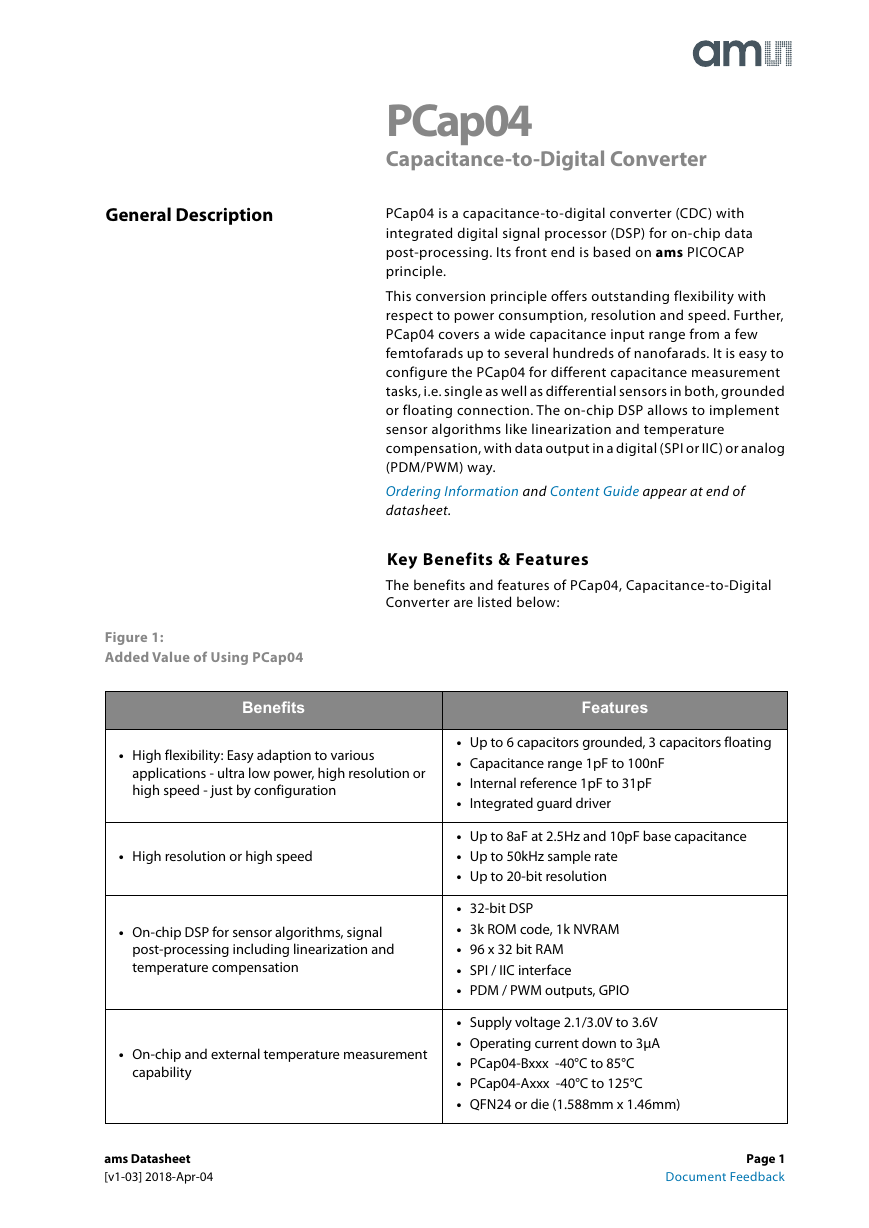
General Description PCap04 Capacitance-to-Digital Converter PCap04 is a capacitance-to-digital converter (CDC) with integrated digital signal processor (DSP) for on-chip data post-processing. Its front end is based on ams PICOCAP principle. This conversion principle offers outstanding flexibility with respect to power consumption, resolution and speed. Further, PCap04 covers a wide capacitance input range from a few femtofarads up to several hundreds of nanofarads. It is easy to configure the PCap04 for different capacitance measurement tasks, i.e. single as well as differential sensors in both, grounded or floating connection. The on-chip DSP allows to implement sensor algorithms like linearization and temperature compensation, with data output in a digital (SPI or IIC) or analog (PDM/PWM) way. Ordering Information and Content Guide appear at end of datasheet. Key Benefits & Features The benefits and features of PCap04, Capacitance-to-Digital Converter are listed below: Figure 1: Added Value of Using PCap04 Benefits Features • High flexibility: Easy adaption to various applications - ultra low power, high resolution or high speed - just by configuration • High resolution or high speed • Up to 6 capacitors grounded, 3 capacitors floating • Capacitance range 1pF to 100nF • Internal reference 1pF to 31pF • Integrated guard driver • Up to 8aF at 2.5Hz and 10pF base capacitance • Up to 50kHz sample rate • Up to 20-bit resolution • On-chip DSP for sensor algorithms, signal post-processing including linearization and temperature compensation • On-chip and external temperature measurement capability • 32-bit DSP • 3k ROM code, 1k NVRAM • 96 x 32 bit RAM • SPI / IIC interface • PDM / PWM outputs, GPIO • Supply voltage 2.1/3.0V to 3.6V • Operating current down to 3μA • PCap04-Bxxx -40°C to 85°C • PCap04-Axxx -40°C to 125°C • QFN24 or die (1.588mm x 1.46mm) ams Datasheet [v1-03] 2018-Apr-04 Page 1 Document Feedback
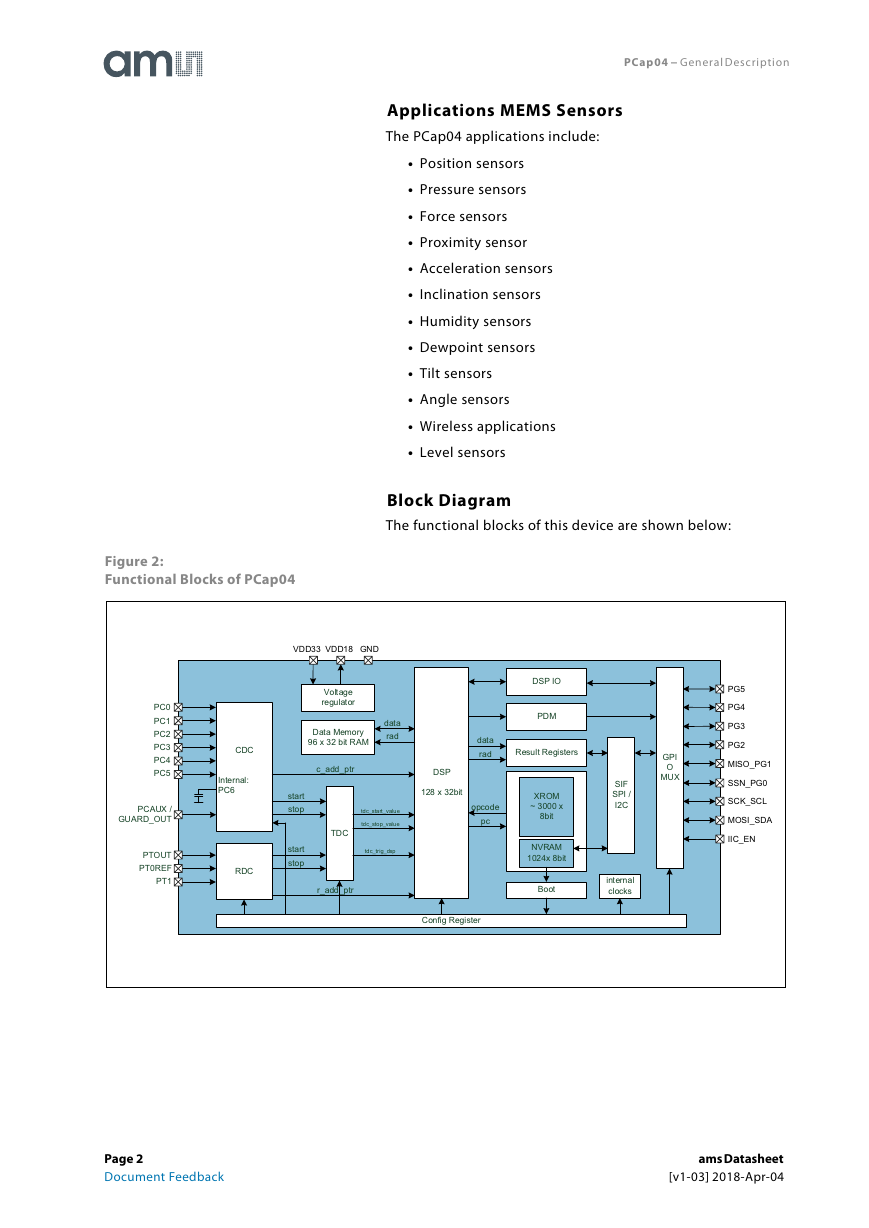
PCap04 − General Description Applications MEMS Sensors The PCap04 applications include: • Position sensors • Pressure sensors • Force sensors • Proximity sensor • Acceleration sensors • Inclination sensors • Humidity sensors • Dewpoint sensors • Tilt sensors • Angle sensors • Wireless applications • Level sensors Block Diagram The functional blocks of this device are shown below: Figure 2: Functional Blocks of PCap04 PC0 PC1 PC2 PC3 PC4 PC5 PCAUX / GUARD_OUT PTOUT PT0REF PT1 CDC Internal: PC6 RDC VDD33 VDD18 GND Voltage regulator Data Memory 96 x 32 bit RAM data rad c_add_ptr start stop start stop TDC tdc_start_value tdc_stop_value tdc_trig_dsp r_add_ptr DSP IO PDM data rad Result Registers DSP 128 x 32bit opcode pc Config Register XROM ~ 3000 x 8bit NVRAM 1024x 8bit Boot SIF SPI / I2C internal clocks GPI O MUX PG5 PG4 PG3 PG2 MISO_PG1 SSN_PG0 SCK_SCL MOSI_SDA IIC_EN Page 2 Document Feedback ams Datasheet [v1-03] 2018-Apr-04
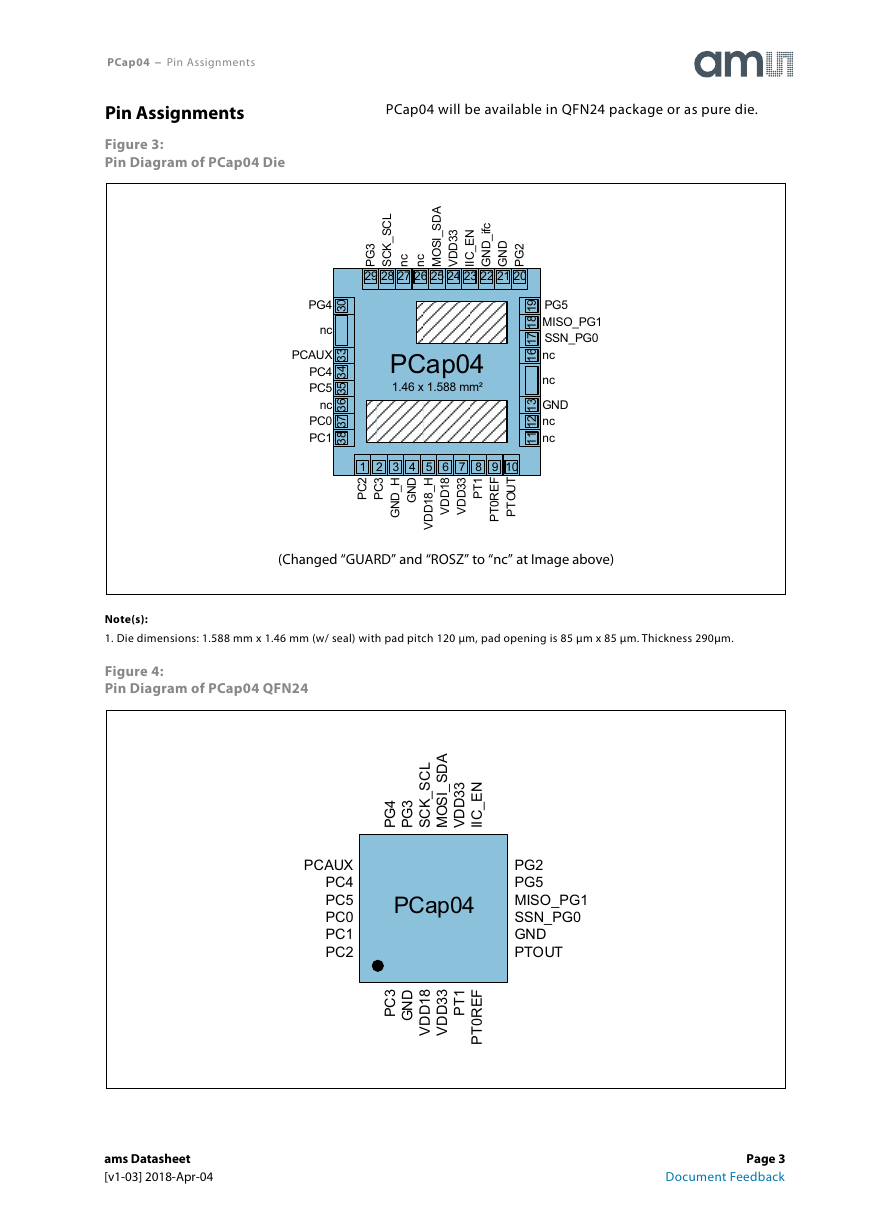
PCap04 − Pin Assignments Pin Assignments Figure 3: Pin Diagram of PCap04 Die PCap04 will be available in QFN24 package or as pure die. A D S _ S O cM n L C S _ K 2 G C P S 28 27 26 25 24 23 22 21 20 3 3 D D V _ D N G N E _ C D N G c n c f i I I I 3 G P 29 9 1 8 1 7 1 6 1 PG5 MISO_PG1 SSN_PG0 nc nc 3 1 2 1 1 1 GND nc nc PG4 0 3 nc PCAUX PC4 PC5 nc PC0 PC1 3 3 4 3 5 3 6 3 7 3 8 3 PCap04 1.46 x 1.588 mm² 1 2 3 4 5 6 7 8 9 10 2 C P 3 C P D N G H _ D N G H _ 8 1 D D V 1 T P 8 1 D D V 3 3 D D V F E R 0 T P T U O T P (Changed “GUARD” and “ROSZ” to “nc” at Image above) Note(s): 1. Die dimensions: 1.588 mm x 1.46 mm (w/ seal) with pad pitch 120 μm, pad opening is 85 μm x 85 μm. Thickness 290μm. Figure 4: Pin Diagram of PCap04 QFN24 A D S _ S O M I L C S _ K C S 3 3 D D V N E _ C I I 4 G P 3 G P 8 1 7 1 6 1 5 1 4 1 3 1 PCAUX PC4 PC5 PC0 PC1 PC2 19 20 21 22 23 24 PCap04 12 11 10 9 8 7 PG2 PG5 MISO_PG1 SSN_PG0 GND PTOUT 123456 3 C P D N G 1 T P 8 1 D D V 3 3 D D V F E R 0 T P ams Datasheet [v1-03] 2018-Apr-04 Page 3 Document Feedback
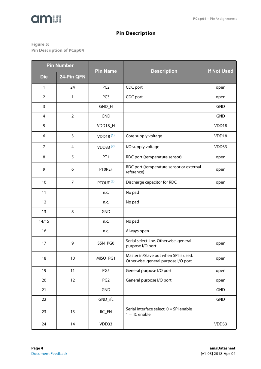
PCap04 − Pin Assignments Pin Description Pin Name Description If Not Used PC2 PC3 GND_H GND VDD18_H VDD18 (1) VDD33 (2) CDC port CDC port Core supply voltage I/O supply voltage PT1 RDC port (temperature sensor) PT0REF RDC port (temperature sensor or external reference) PTOUT (3) Discharge capacitor for RDC n.c. n.c. GND n.c. n.c. No pad No pad No pad Always open SSN_PG0 MISO_PG1 Serial select line. Otherwise, general purpose I/O port Master in/Slave out when SPI is used. Otherwise, general purpose I/O port General purpose I/O port General purpose I/O port Serial interface select, 0 = SPI enable 1 = IIC enable PG5 PG2 GND GND_ifc IIC_EN VDD33 open open GND GND VDD18 VDD18 VDD33 open open open open open open open GND GND VDD33 Figure 5: Pin Description of PCap04 Pin Number Die 24-Pin QFN 1 2 3 4 5 6 7 8 9 10 11 12 13 14/15 16 17 18 19 20 21 22 23 24 24 1 2 3 4 5 6 7 8 9 10 11 12 13 14 Page 4 Document Feedback ams Datasheet [v1-03] 2018-Apr-04
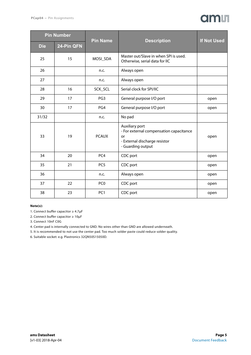
PCap04 − Pin Assignments Pin Number Die 24-Pin QFN Pin Name Description If Not Used 25 26 27 28 29 30 31/32 33 34 35 36 37 38 15 MOSI_SDA Master out/Slave in when SPI is used. Otherwise, serial data for IIC n.c. n.c. Always open Always open SCK_SCL Serial clock for SPI/IIC PG3 PG4 n.c. PCAUX PC4 PC5 n.c. PC0 PC1 General purpose I/O port General purpose I/O port No pad Auxiliary port - For external compensation capacitance or - External discharge resistor - Guarding output CDC port CDC port Always open CDC port CDC port open open open open open open open open 16 17 17 19 20 21 22 23 Note(s): 1. Connect buffer capacitor ≥ 4.7μF 2. Connect buffer capacitor ≥ 10μF 3. Connect 10nF C0G 4. Center pad is internally connected to GND. No wires other than GND are allowed underneath. 5. It is recommended to not use the center pad. Too much solder paste could reduce solder quality. 6. Suitable socket: e.g. Plastronics 32QN50S15050D. ams Datasheet [v1-03] 2018-Apr-04 Page 5 Document Feedback
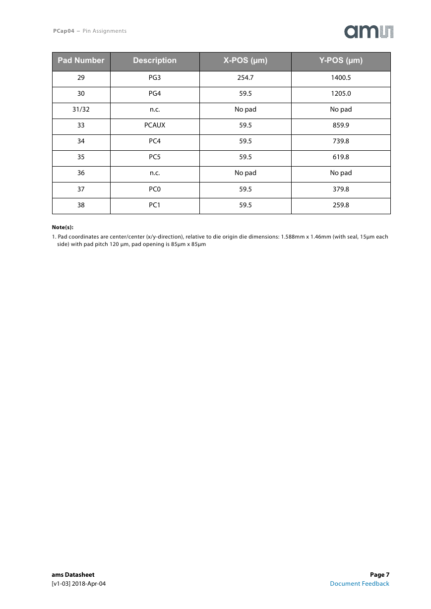
PCap04 − Pin Assignments Pad Coordinates Figure 6: Pad Coordinates of PCap04 Pad Number Description X-POS (µm) Y-POS (µm) 1 2 3 4 5 6 7 8 9 10 11 12 13 14/15 16 17 18 19 20 21 22 23 24 25 26 27 28 PC2 PC3 GND_H GND VDD18_H VDD18 VDD33 PT1 PT0REF PTOUT n.c. n.c. GND n.c. n.c. SSN_PG0 MICO_PG1 PG5 PG2 GND GND_ifc IIC_EN VDD33 MOSI_SDA n.c. n.c. SCK_SCL 260.0 380.0 488.0 608.0 728.0 848.0 968.0 1088.0 1208.0 1328.0 No pad No pad 1528.5 No pad No pad 1528.5 1528.5 1528.5 1333.0 1213.0 1093.0 973.0 853.0 733.0 No pad No pad 374.7 59.5 59.5 59.5 59.5 59.5 59.5 59.5 59.5 59.5 59.5 No pad No pad 501.0 No pad No pad 965.0 1085.0 1205.0 1400.5 1400.5 1400.5 1400.5 1400.5 1400.5 No pad No pad 1400.5 Page 6 Document Feedback ams Datasheet [v1-03] 2018-Apr-04
PCap04 − Pin Assignments Pad Number Description X-POS (µm) Y-POS (µm) 29 30 31/32 33 34 35 36 37 38 PG3 PG4 n.c. PCAUX PC4 PC5 n.c. PC0 PC1 254.7 59.5 No pad 59.5 59.5 59.5 No pad 59.5 59.5 1400.5 1205.0 No pad 859.9 739.8 619.8 No pad 379.8 259.8 Note(s): 1. Pad coordinates are center/center (x/y-direction), relative to die origin die dimensions: 1.588mm x 1.46mm (with seal, 15μm each side) with pad pitch 120 μm, pad opening is 85μm x 85μm ams Datasheet [v1-03] 2018-Apr-04 Page 7 Document Feedback
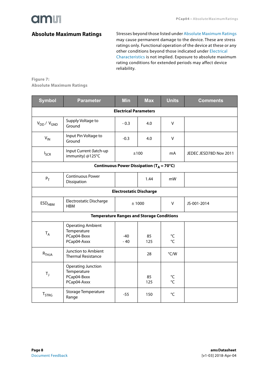
PCap04 − Absolute Maximum Ratings Stresses beyond those listed under Absolute Maximum Ratings may cause permanent damage to the device. These are stress ratings only. Functional operation of the device at these or any other conditions beyond those indicated under Electrical Characteristics is not implied. Exposure to absolute maximum rating conditions for extended periods may affect device reliability. Absolute Maximum Ratings Figure 7: Absolute Maximum Ratings Symbol Parameter Min Max Units Comments VDD / VGND Supply Voltage to Ground Input Pin Voltage to Ground Input Current (latch-up immunity) @125°C Electrical Parameters - 0.3 -0.3 4.0 4.0 V V ±100 mA JEDEC JESD78D Nov 2011 VIN ISCR PT Continuous Power Dissipation (TA = 70°C) Continuous Power Dissipation 1.44 mW Electrostatic Discharge ESDHBM Electrostatic Discharge HBM ± 1000 V JS-001-2014 Temperature Ranges and Storage Conditions TA RTHJA TJ TSTRG -40 - 40 Operating Ambient Temperature PCap04-Bxxx PCap04-Axxx Junction to Ambient Thermal Resistance Operating Junction Temperature PCap04-Bxxx PCap04-Axxx Storage Temperature Range -55 85 125 28 85 125 150 °C °C °C/W °C °C °C Page 8 Document Feedback ams Datasheet [v1-03] 2018-Apr-04
分享到:
收藏