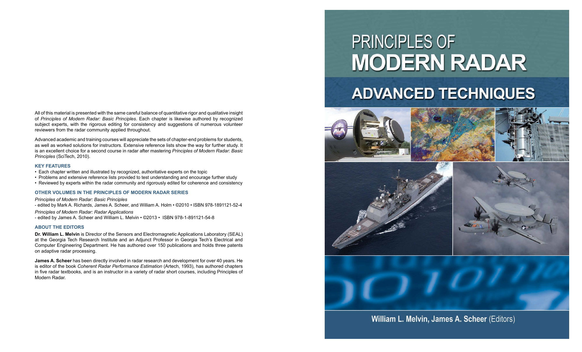
Principles of Modern Radar, Vol. II: Advanced Techniques
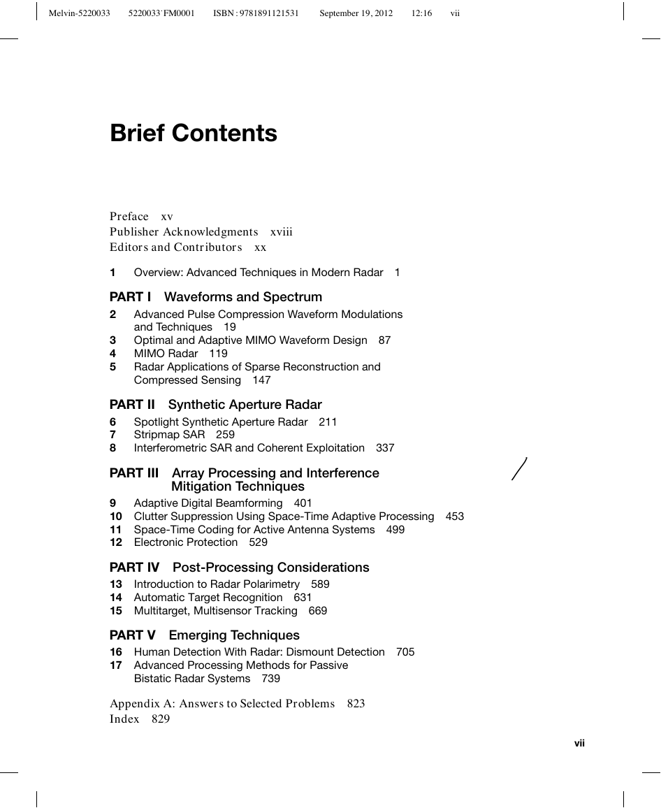
Brief Contents
Contents
Preface
What this Book Addresses
Why this Book was Written
How the Content was Developed
The History of the POMR Series
Acknowledgements
To our Readers
Publisher Acknowledgments
Editors and Contributors
1 Overview: Advanced Techniques in Modern Radar
1.1 Introduction
1.2 Radar Modes
1.3 Radar and System Topologies
1.4 Topics in Advanced Techniques
1.4.1 Waveforms and Spectrum
1.4.2 Synthetic Aperture Radar
1.4.3 Array Processing and Interference Mitigation Techniques
1.4.4 Post-Processing Considerations
1.4.5 Emerging Techniques
1.5 Comments
1.6 References
PART I: Waveforms and Spectrum
2 Advanced Pulse Compression Waveform Modulations and Techniques
2.1 Introduction
2.1.1 Organization
2.1.2 Key Points
2.1.3 Notation
2.1.3.1 Common Variables
2.1.3.2 Stretch Processing
2.1.3.3 Stepped Chirp Waveforms
2.1.3.4 Nonlinear Frequency Modulated Waveforms
2.1.3.5 Stepped Frequency Waveforms
2.1.3.6 Quadriphase Codes
2.1.3.7 Mismatched Filters
2.1.4 Acronyms
2.2 Stretch Processing
2.2.1 Introduction
2.2.2 Processing Bandwidth
2.2.3 Technique Overview
2.2.4 Implementation
2.2.4.1 Transmit Waveform
2.2.4.2 Receiver
2.2.4.3 Processor Architecture
2.2.4.4 Spectrum of the Baseband Signal
2.2.4.5 Range Resolution
2.2.4.6 SNR Loss
2.2.4.7 Oscillator Over Sweep
2.2.4.8 Filter Bandwidth
2.2.4.9 Compressed Range Response
2.2.4.10 Discrete Fourier Transform
2.2.5 Example System Parameters
2.2.6 Processing Gain
2.2.7 Range-Sidelobe Suppression
2.2.8 Range-Doppler Coupling
2.2.9 Summary
2.3 Stepped Chirp Waveforms
2.3.1 Introduction
2.3.2 Transmit Waveform
2.3.3 Received Waveform
2.3.4 Processing Options
2.3.4.1 Time Domain
2.3.4.2 Frequency Domain
2.3.4.3 Summary of Frequency-Domain Processing Steps
2.3.4.4 Frequency-Domain Example
2.3.5 Summary
2.4 Nonlinear Frequency Modulated Waveforms
2.4.1 Functional Relationship
2.4.1.1 Principle of Stationary Phase
2.4.1.2 Inverse Functions
2.4.1.3 Parametric Equations
2.4.2 Design Approaches
2.4.3 Design Example
2.4.4 Doppler Analysis
2.4.5 Summary
2.5 Stepped Frequency Waveforms
2.5.1 Waveform Description
2.5.2 Phase Rotation Used to Measure Range
2.5.3 Receiver and Processing Architecture
2.5.4 Creating a Range Profile
2.5.5 Straddle Loss and Range Ambiguities
2.5.5.1 Straddle Loss
2.5.5.2 Range Ambiguities Associated with Frequency Stepping
2.5.5.3 Ambiguities in a Dynamic Target Environment
2.5.5.4 Choosing a Pulse Width in a Target- or Clutter-Rich Environment
2.5.5.5 Waveform Parameter Trade Summary
2.5.6 Impacts of Doppler
2.5.7 Summary
2.6 Quadriphase Signals
2.6.1 Introduction
2.6.2 BTQ Transformation
2.6.3 Quadriphase Waveform
2.6.4 Waveform Properties
2.6.4.1 Spectrum
2.6.4.2 Match Filtered Response
2.6.4.3 Ambiguity Surface
2.6.5 Summary
2.7 Mismatched Filters
2.7.1 Introduction
2.7.2 Performance Metrics
2.7.3 Mismatched Filter Approaches
2.7.3.1 Minimum ISR Filter
2.7.3.2 Minimum ISR Example
2.7.3.3 Doppler Tolerance
2.7.3.4 Tailoring the Sidelobe Response
2.7.3.5 Reduced Peak Sidelobe Filters
2.7.4 Summary
2.8 Further Reading
2.9 References
2.10 Problems
3 Optimal and Adaptive MIMO Waveform Design
3.1 Introduction
3.1.1 Organization
3.1.2 Key Points
3.1.3 Acronyms
3.2 Optimum MIMO Waveform Design for the Additive Colored Noise Case
3.3 Optimum MIMO Design for Maximizing Signal-to-Clutter Ratio
3.4 Optimum MIMO Design for Target Identification
3.5 Constrained Optimum MIMO Radar
3.6 Adaptive MIMO Radar
3.6.1 Transmit-Independent Channel Estimation
3.6.2 Dynamic MIMO Calibration
3.7 Summary
3.8 Further Reading
3.9 References
3.10 Problems
4 MIMO Radar
4.1 Introduction
4.1.1 Organization
4.1.2 Notation
4.1.3 Acronyms
4.2 An Overview of MIMO Radar
4.3 The MIMO Virtual Array
4.4 MIMO Radar Signal Processing
4.4.1 Signal Model
4.4.2 MIMO Signal Correlation Matrix
4.4.3 MIMO Spatial Beamforming
4.4.4 MIMO Gain
4.4.5 Phased Array versus Orthogonal Waveforms
4.5 Waveforms for MIMO Radar
4.5.1 Classes of Waveforms for MIMO Radar
4.5.2 MIMO Range Response
4.5.3 Example: Up- and Down-Chirp
4.6 Applications of MIMO Radar
4.6.1 MIMO SAR
4.6.2 MIMO GMTI
4.6.3 Distributed Apertures
4.6.4 Beampattern Synthesis
4.7 Summary
4.8 Further Reading
4.9 References
4.10 Problems
5 Radar Applications of Sparse Reconstruction and Compressed Sensing
5.1 Introduction
5.1.1 Organization
5.1.2 Key Points
5.1.3 Notation
5.1.4 Acronyms
5.2 CS Theory
5.2.1 The Linear Model
5.2.2 The Linear Model in Radar
5.2.2.1 Radio Frequency Tomography Example
5.2.2.2 The Ambiguity Function
5.2.2.3 Multichannel Example
5.2.2.4 Comments
5.2.3 Regularization of the Linear Model through Sparsity
5.2.4 l1 Regularization
5.2.5 Performance Guarantees
5.2.5.1 Kruskal Rank
5.2.5.2 The Restricted Isometry Property
5.2.5.3 Matrices that Satisfy RIP
5.2.5.4 Mutual Coherence
5.3 SR Algorithms
5.3.1 Penalized Least Squares
5.3.1.1 Equivalent Optimization Problems and the Pareto Frontier
5.3.1.2 Solvers
5.3.2 Thresholding Algorithms
5.3.2.1 Soft Thresholding
5.3.2.2 Hard Thresholding
5.3.3 Iterative Reweighting Schemes
5.3.4 Greedy Methods
5.3.5 Bayesian Approaches
5.3.5.1 Averaging Solutions
5.3.5.2 Graphical Models
5.3.6 Structured Sparsity
5.3.7 Matrix Uncertainty and Calibration
5.3.8 Final Thoughts
5.4 Sample Radar Applications
5.4.1 Moving Target Imaging
5.4.2 Multipass 3-D Circular SAR
5.4.3 Multistatic Underground Imaging
5.4.4 A Herglotz Kernel Method
5.4.5 Single-Pulse Target Detection
5.5 Summary
5.6 Further Reading
5.7 Acknowledgments
5.8 References
5.9 Problems
PART II: Synthetic Aperture Radar
6 Spotlight Synthetic Aperture Radar
6.1 Introduction
6.1.1 Organization
6.1.2 Key Points
6.1.3 Notation
6.1.4 Acronyms
6.2 Mathematical Background
6.2.1 The Fourier Transform
6.2.2 The Sinc Function
6.2.3 Spatial Frequency and Plane Waves
6.2.4 Fundamental Assumptions of SAR Imaging
6.3 Spotlight SAR Nomenclature
6.4 Sampling Requirements and Resolution
6.4.1 Temporal Sampling Requirements and Range Resolution
6.4.1.1 Deramp on Receive
6.4.2 Along-Track Sampling Requirements
6.4.3 PRF Constraints
6.4.4 Cross-Range Resolution
6.5 Image Reconstruction
6.5.1 The Tomographic Paradigm
6.5.2 The Polar Formatting Algorithm
6.5.3 Other Reconstruction Algorithms
6.6 Image Metrics
6.6.1 Additive and Multiplicative Noise
6.6.1.1 Ambiguity-to-Signal Ratio
6.6.1.2 Integrated Sidelobe Ratio
6.6.1.3 Quantization Noise
6.6.2 Rating Image Quality
6.7 Phase Error Effects
6.7.1 Linear Phase Errors
6.7.2 Quadratic Phase Errors
6.7.3 Sinusoidal Phase Errors
6.7.4 Wideband Phase Errors
6.8 Autofocus
6.8.1 Phase Difference Autofocus
6.8.2 Phase Gradient Autofocus
6.9 Summary and Further Reading
6.10 References
6.11 Problems
7 Stripmap SAR
7.1 Introduction
7.1.1 Organization
7.1.2 Key Points
7.1.3 Notation
7.1.4 Acronyms
7.2 Review of Radar Imaging Concepts
7.2.1 Resolution and Sampling
7.2.2 Point Spread Response
7.2.3 Image Formation Survey
7.2.4 Doppler Beam Sharpening
7.3 Doppler Beam Sharpening Extensions
7.3.1 Azimuth Dechirp
7.3.2 Range Migration Compensation
7.3.3 Notes on Doppler Beam Sharpening
7.4 Range-Doppler Algorithms
7.4.1 Matched Filtering
7.4.2 Range Stacking Algorithm
7.4.3 Range-Doppler Algorithm
7.4.3.1 Full Range-Doppler Algorithm
7.4.3.2 Depth of Focus
7.4.3.3 Frequency-Domain PSR for RDA
7.4.3.4 RDA Approximations
7.4.3.5 The Modified Range-Doppler Algorithm
7.4.3.6 Notes on the Range-Doppler Algorithm
7.5 Range Migration Algorithm
7.5.1 RDA Revisited
7.5.2 Coordinate Systems and Frequencies
7.5.3 Stolt Interpolation and RMA
7.5.4 Simulated RMA Examples
7.5.5 Stolt Approximation
7.5.6 Chirp Scaling Algorithm
7.6 Operational Considerations
7.6.1 PRF Lower Limits
7.6.2 PRF Upper Limits
7.6.3 Antenna Area and System Utility
7.6.4 Slant Plane and Ground Plane
7.6.5 Other Imaging Approahces
7.6.6 Squinted Operation
7.7 Applications
7.7.1 Remote Sensing Applications
7.7.2 Penetration Applications
7.8 Summary
7.9 Further Reading
7.10 References
7.11 Problems
8 Interferometric SAR and Coherent Exploitation
8.1 Introduction
8.1.1 Organization
8.1.2 Key Points
8.1.3 Notation
8.1.4 Acronyms
8.2 Digital Terrain Models
8.3 Estimating Elevation Profiles Using Radar Echo Phase
8.3.1 The Effect of Scatterer Elevation on 2-D SAR Images
8.3.2 Measuring Depression Angle with Pairs of Range Measurements
8.3.3 Estimating Elevation Variations from Phase Measurements
8.3.4 Wrapped Phase
8.3.5 Spatial Baseline Effect on Accuracy and Fringe Height
8.3.6 Estimating Elevation Relative to a Reference Profile
8.3.7 Range Foreshortening and Layover
8.3.8 Other Three-Dimensional Coherent SAR Techniques
8.4 InSAR Operational Considerations
8.4.1 One-Pass versus Repeat-Pass Operation
8.4.2 Spaceborne versus Airborne InSAR
8.4.3 Relation to Other Technologies for Estimating Elevation Profiles
8.5 InSAR Processing Steps
8.5.1 Image Pair Generation and Registration
8.5.2 Estimation of the Wrapped Interferometric Phase Difference
8.5.3 Two-Dimensional Phase Unwrapping
8.5.3.1 Path-Following Method
8.5.3.2 Least Squares Method
8.5.3.3 Network Flow Method
8.5.4 Differences and Commonality of 2-D Phase Unwrapping Methods
8.5.5 Multibaseline InSAR
8.5.6 Estimation of the Terrain Map from the Unwrapped Phase
8.5.7 Absolute Elevation Estimation
8.5.8 Orthorectification and Geocoding
8.6 Error Sources
8.6.1 Coherence and Statistical Errors
8.6.1.1 Thermal and Quantization Noise
8.6.1.2 Baseline Decorrelation
8.6.1.3 Temporal Decorrelation
8.6.1.4 Atmospheric and Weather Effects
8.6.1.5 Interferogram Phase Statistics and Multilook Averaging
8.6.1.6 Coherence and Interferometric System Design
8.6.2 Systematic Errors
8.6.2.1 Sensor Geometry Errors
8.6.2.2 Other Systematic Error Sources
8.7 Some Notable InSAR Systems
8.7.1 Spaceborne Systems
8.7.2 Airborne Systems
8.8 Other Coherent Exploitation Techniques
8.8.1 Terrain Motion Mapping
8.8.2 Coherent Change Detection
8.8.3 Along-Track Interferometry
8.9 Summary
8.10 Further Reading
8.11 References
8.12 Problems
PART III: Array Processing and Interference Mitigation Techniques
9 Adaptive Digital Beamforming
9.1 Introduction
9.1.1 Organization
9.1.2 Key Points
9.1.3 Notation
9.1.4 Acronyms
9.2 Digital Beamforming Fundamentals
9.2.1 DBF Implementation Challenges
9.2.2 Subarrays
9.2.3 Benefits of Digital Beamforming
9.2.4 Multiple Simultaneous Beams on Receive
9.3 Adaptive Jammer Cancellation
9.3.1 Wiener Filter
9.3.2 Maximum SINR
9.3.3 Constrained Optimization
9.3.3.1 Linearly Constrained Minimum Variance
9.3.3.2 Generalized Sidelobe Canceller
9.3.3.3 Beamformer Constraint Design
9.3.4 Adaptive Weight Estimation
9.3.4.1 Sample Matrix Inversion
9.3.4.2 Weight Jitter Stabilization
9.3.4.3 Cholesky Factorization
9.3.5 Performance Metrics
9.3.5.1 Cancellation Ratio
9.3.5.2 Residue
9.3.5.3 SINR
9.3.5.4 Antenna Patterns
9.3.5.5 Cumulative Distribution Functions
9.4 Adaptive Beamformer Architectures
9.4.1 Sidelobe Blanker
9.4.2 Sidelobe Canceller
9.4.3 Beamspace Adaptive Cancellation
9.4.4 Subarray Space Adaptive Cancellation
9.5 Wideband Cancellation
9.5.1 Jammer Dispersion over Bandwidth
9.5.2 Joint Spatial-Frequency Domain Wideband Beamformer
9.5.3 Subbanding
9.5.4 LFM/Strectch
9.6 Summary
9.7 Further Reading
9.8 References
9.9 Problems
10 Clutter Suppression Using Space-Time Adaptive Processing
10.1 Introduction
10.1.1 STAP Overview
10.1.2 Organization
10.1.3 Key Points
10.1.4 Notation and Operations
10.1.5 Variable Names
10.1.6 Acronyms
10.2 Space-Time Signal Representation
10.2.1 Spatial Sampling and Beamforming
10.2.2 Temporal Sampling and Doppler Processing
10.2.3 Space-Time Signals
10.3 Space-Time Properties of Ground Clutter
10.4 Space-Time Processing
10.4.1 Performance Metrics
10.4.1.1 Detection
10.4.1.2 SINR Loss
10.4.1.3 Improvement Factor
10.5 STAP Fundamentals
10.5.1 Maximum SINR Filter
10.5.2 Minimum Variance Beamformer
10.5.3 Generalized Sidelobe Canceller
10.6 STAP Processing Architectures and Methods
10.6.1 Reduced-Dimension STAP
10.6.1.1 Element Space Post-Doppler
10.6.1.2 Post-Doppler Beamspace
10.6.1.3 Post-Doppler STAP Performance
10.6.2 Pre-Doppler STAP
10.6.3 Reduced-Rank STAP
10.6.4 Angle and Doppler Estimation
10.6.5 Processing Block Diagram
10.7 Other Considerations
10.7.1 Heterogeneous Clutter
10.7.2 Nonstationary Angle-Doppler Region of Support
10.7.3 Computational Burden
10.8 Further Reading
10.9 Summary
10.10 References
10.11 Problems
11 Space-Time Coding for Active Antenna Systems
11.1 Introduction
11.2 Colored Space-Time Exploration
11.2.1 Digital Beamforming (DBF)
11.2.1.1 Principle and objectives
11.2.1.2 Limitations of Digital Beam Forming
11.2.2 Colored transmission, or space-time coding
11.2.2.1 Principles
11.2.2.2 Circulating pulse
11.2.2.3 Fast Scanning (intra-pulse scanning) [6]
11.2.2.4 Circulating code [7],[5]
11.2.2.5 Bidimensional frequency coding [15]
11.2.3 Target coherence and diversity gains
11.2.3.1 Target coherence
11.2.3.2 Diversity gain
11.2.4 Colored transmission trade-offs and applications
11.3 Interleaved Scanning (Slow-Time Space-Time Coding)
11.4 Code Selection and Grating Lobes Effects
11.4.1 Time domain: periodic vs high time-bandwidth waveforms
11.4.2 Space domain: sub-arrays and grating lobes
11.4.3 Coding strategy
11.5 Wideband MTI [12], [4]
11.6 Conclusion
11.7 Further Reading
11.8 References
11.9 Problems
12 Electronic Protection
12.1 Introduction
12.1.1 Organization
12.1.2 Key Points
12.1.3 Notation
12.1.4 Abbreviations
12.2 Electronic Attack
12.2.1 Electronic Attack Overview
12.2.2 Jammer Types
12.2.2.1 Noncoherent Jammers
12.2.2.2 Coherent Jammers
12.2.3 Masking EA Techniques
12.2.3.1 Noncoherent Masking Techniques
12.2.3.2 Coherent Masking Techniques
12.2.4 Deception EA Techniques
12.2.4.1 False Targets
12.2.4.2 Range and Velocity Track Deception
12.2.4.3 Angle Track Deception
12.3 EW-Related Formulas
12.3.1 Signal and Thermal Noise Formulas
12.3.2 Keeping Track of Losses
12.3.3 Noise Jammer Formulas
12.3.4 Noise Jammer Computation Example
12.3.5 Coherent Jammer Formulas
12.3.6 Coherent Jammer Computation Example
12.3.7 Jammer Received Power Computation
12.3.8 Jammer Received Power Example
12.4 EP Overview
12.5 Antenna-Based EP
12.5.1 Low Sidelobes
12.5.2 Sector Blanking
12.5.3 Sidelobe Blanking
12.5.4 Sidelobe Cancellation
12.5.5 Main Lobe Cancellation
12.5.6 Narrow Beamwidth
12.5.7 Random Beam Scanning
12.5.8 Passive Conical Scanning
12.5.9 Monopulse Angle Measurement
12.5.10 Low Cross Polarization Antenna
12.6 Transmitter-Based EP
12.6.1 High Peak Power
12.6.2 Transmit Power Reduction
12.6.3 Emission Control
12.7 Exciter-Based EP
12.7.1 Wide-Pulse Waveform
12.7.2 Multiple-Pulse Waveform
12.7.3 Burnthrough Waveforms
12.7.4 Narrow-Pulse Range Resolution
12.7.5 Pulse Compression Range Resolution
12.7.6 Doppler Resolution Waveform
12.7.7 Frequency Variation
12.7.8 Multiple Simultaneous Frequency Radiation
12.7.9 Pulse Repetition Frequency Variation
12.8 Receiver-Based EP
12.8.1 RF Preselection
12.8.2 Image Rejection
12.8.3 Wide Instantaneous Dynamic Range
12.8.4 Notch Filtering
12.8.5 Wideband Limiting
12.8.6 Guard Band Channel
12.8.7 Noncoherent Detection Channel
12.8.8 Least Jammed Frequency Selection
12.9 Signal Processor-Based EP
12.9.1 Total Energy Detector
12.9.2 Alternate Constant False Alarm Rate Detection
12.9.3 Angle Variance
12.9.4 Data Editing
12.9.5 Guard Gates
12.9.6 Leading-Edge Track
12.10 Data Processor-Based EP
12.10.1 Angle Alignment Correlation
12.10.2 Radar Cross Section Statistics
12.10.3 Radar Cross Section Step Detection
12.10.4 Range-Doppler Track Comparison
12.10.5 Track Filter Acceleration Limit
12.10.6 Track-on-Jam
12.10.7 Angle Gating
12.11 Summary
12.12 Further Reading
12.13 References
12.14 Problems
PART IV: Post-Processing Considerations
13 Introduction to Radar Polarimetry
13.1 Introduction
13.1.1 Organization
13.1.2 Key Points
13.1.3 List of Symbols
13.1.4 Acronyms
13.2 Polarization
13.2.1 Fundamentals of Wave Polarization
13.2.1.1 Linear Polarization
13.2.1.2 Circular Polarization
13.2.1.3 Eliptical Polarization
13.2.2 Stokes Parameters and Poincaré Sphere
13.3 Scattering Matrix
13.3.1 Sinclair Formulation
13.3.2 Optimal Polarizations
13.3.3 Partial Polarization and Mueller Matrix
13.4 Radar Applications of Polarimetry
13.4.1 Targets
13.4.1.1 Target Feature Extraction
13.4.2 Rain Clutter
13.4.3 Ground Clutter
13.4.4 Sea Clutter
13.5 Measurement of the Scattering Matrix
13.6 Summary
13.7 Further Reading
13.8 References
13.9 Problems
14 Automatic Target Recognition
14.1 Introduction
14.2 Unified Framework for ATR
14.3 Metrics and Performance Prediction
14.3.1 Common Metrics
14.3.2 Performance Prediction
14.3.2.1 Performance Prediction in the Neyman-Pearson Framework
14.3.2.2 Performance Prediction in the Bayesian Framework
14.3.2.3 Comparison of Algorithms Via the Wald Sequential Test
14.3.3 Using Performance Prediction Tools in the Design Process
14.4 Synthetic Aperture Radar
14.4.1 Step 1: Identify the Target Set
14.4.2 Step 2: Select the Feature Set
14.4.2.1 Types of Sar
14.4.2.2 Candidate Features
14.4.3 Observe the Feature Set
14.4.3.1 Observation Conditions
14.4.3.2 Image Formation and Pre-processing Techniques
14.4.3.3 Pre-screening and Discrimination Algorithms
14.4.4 Test the Feature Set
14.4.5 Summary of Synthetic Aperture Radar
14.5 Inverse Synthetic Aperture Radar
14.5.1 Image Formation
14.5.2 Scattering Models
14.5.3 Candidate Features
14.6 Passive Radar ATR
14.7 High-Resolution Range Profiles
14.8 Summary
14.9 Further Reading
14.10 References
14.11 Problems
15 Multitarget, Multisensor Tracking
15.1 Review of Tracking Concepts
15.1.1 Covariances
15.1.2 Measurement-to-track Data Association
15.1.2.1 Gating
15.1.2.2 Cost Functions
15.1.2.3 Assignment Algorithms
15.1.3 Track Filtering
15.2 Multitarget Tracking
15.2.1 Measurement-to-track Data Association
15.2.1.1 Feature-assisted Tracking
15.2.1.2 Multiple Hypothesis Tracking
15.2.1.3 Cluster Tracking
15.2.2 Modeling Target Dynamics
15.2.2.1 Interacting Multiple Model (IMM) Estimators
15.2.3 VS-IMM Estimators
15.3 Multisensor Tracking
15.3.1 Sensor Fusion Architectures
15.3.2 Measurement-level Fusion and Associated Challenges
15.3.3 Track-level Fusion and Associated Challenges
15.3.4 Sensor Fusion Challenges Common to Both Paradigms
15.4 Summary
15.5 Further Reading
15.6 References
15.7 Problems
PART V: Emerging Techniques
16 Human Detection With Radar: Dismount Detection
16.1 Introduction
16.1.1 Key Points
16.1.2 Notation
16.1.3 Acronyms
16.2 Characterizing the Human Radar Return
16.2.1 Expected Radar Return from a Human Target
16.2.2 Human Kinematic Models
16.2.3 Computing Time-Varying Ranges with the Boulic-Thalmann Model
16.2.4 Modeling Human Radar Cross Section
16.3 Spectrogram Analysis of Human Returns
16.4 Technical Challenges in Human Detection
16.4.1 Slow-Moving Target Detection and GMTI Radars
16.4.2 Mitigating the Effects of Clutter with STAP
16.4.3 Inherent Output SNR Losses for Human Targets in Typical Detectors
16.5 Exploiting Knowledge for Detection and Classification
16.6 Summary
16.7 Further Reading
16.8 References
16.9 Problems
17 Advanced Processing Methods for Passive Bistatic Radar Systems
17.1 Introduction
17.1.1 Organization
17.1.2 Key Points
17.1.3 Notation
17.1.4 Acronyms
17.2 Evaluation of the 2D-CCF for the Passive Radar Coherent Integration
17.2.1 Efficient Implementations of the 2D-CCF Based on the Fast Fourier Transform
17.2.2 Suboptimum Implementations of the 2D-CCF
17.3 Direct Signal and Multipath/Clutter Cancellation Techniques
17.3.1 Extensive Cancellation Algorithm
17.3.2 ECA Batches
17.3.3 ECA Batches and Stages (ECA-B&S)
17.4 Signal Processing Techniques for Reference Signal Cleaning and Reconstruction
17.4.1 Constant Modulus Algorithm for Reference Signal Cleaning Using Analog Modulation
17.4.2 Reference Signal Reconstruction for Digital Transmissions
17.5 2D-CCF Sidelobe Control
17.5.1 Range Sidelobes Control for 2D-CCF in WiFi-Based PBR
17.5.2 Range Sidelobes Control for 2D-CCF in WiMAX-Based PBR
17.5.3 2D-CCF Shape Control for DVB-T Signals
17.6 Multichannel Processing for Detection Performance Improvement
17.6.1 Linear–Nonlinear Integration of Multiple Frequency Passive Radar Channels
17.6.2 Exploitation of Multiple Polarimetric Passive Radar Channels
17.6.3 Adaptive Antenna Array for
Passive Radar
17.7 Summary
17.8 Acknowledgments
17.9 Further Reading
17.10 References
17.11 Problems
Appendix A: Answers to Selected Problems
Supplements
Index


 2023年江西萍乡中考道德与法治真题及答案.doc
 2012年重庆南川中考生物真题及答案.doc
 2013年江西师范大学地理学综合及文艺理论基础考研真题.doc
 2020年四川甘孜小升初语文真题及答案I卷.doc
 2020年注册岩土工程师专业基础考试真题及答案.doc
 2023-2024学年福建省厦门市九年级上学期数学月考试题及答案.doc
 2021-2022学年辽宁省沈阳市大东区九年级上学期语文期末试题及答案.doc
 2022-2023学年北京东城区初三第一学期物理期末试卷及答案.doc
 2018上半年江西教师资格初中地理学科知识与教学能力真题及答案.doc
 2012年河北国家公务员申论考试真题及答案-省级.doc
 2020-2021学年江苏省扬州市江都区邵樊片九年级上学期数学第一次质量检测试题及答案.doc
 2022下半年黑龙江教师资格证中学综合素质真题及答案.doc