Lontium Semiconductor
LT6911UXC Datasheet R0.9
LONTIUM SEMICONDUCTOR
CORPORATION
ClearEdge Technology
HDMI2.0 to Dual-Port MIPI DSI/CSI with Audio
LT6911UXC
Datasheet
We produce mixed-signal products for a better digital world!
Confidential
1
�
Lontium Semiconductor
LT6911UXC Datasheet R0.9
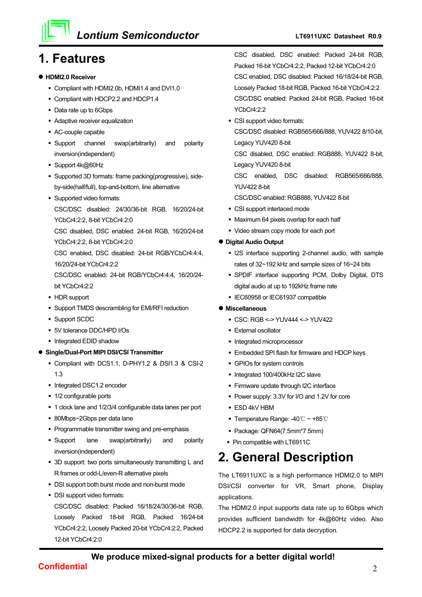
1. Features
HDMI2.0 Receiver
CSC disabled, DSC enabled: Packed 24-bit RGB,
Packed 16-bit YCbCr4:2:2, Packed 12-bit YCbCr4:2:0
CSC enabled, DSC disabled: Packed 16/18/24-bit RGB,
Loosely Packed 18-bit RGB, Packed 16-bit YCbCr4:2:2
CSC/DSC enabled: Packed 24-bit RGB, Packed 16-bit
YCbCr4:2:2
CSI support video formats:
CSC/DSC disabled: RGB565/666/888, YUV422 8/10-bit,
Legacy YUV420 8-bit
CSC disabled, DSC enabled: RGB888, YUV422 8-bit,
Legacy YUV420 8-bit
CSC enabled, DSC disabled: RGB565/666/888,
YUV422 8-bit
CSC/DSC enabled: RGB888, YUV422 8-bit
CSI support interlaced mode
Maximum 64 pixels overlap for each half
Video stream copy mode for each port
Digital Audio Output
I2S interface supporting 2-channel audio, with sample
rates of 32~192 kHz and sample sizes of 16~24 bits
SPDIF interface supporting PCM, Dolby Digital, DTS
digital audio at up to 192kHz frame rate
IEC60958 or IEC61937 compatible
Miscellaneous
CSC: RGB <-> YUV444 <-> YUV422
External oscillator
Integrated microprocessor
Embedded SPI flash for firmware and HDCP keys
GPIOs for system controls
Integrated 100/400kHz I2C slave
Firmware update through I2C interface
Power supply: 3.3V for I/O and 1.2V for core
ESD 4kV HBM
Temperature Range: -40℃ ~ +85℃
Package: QFN64(7.5mm*7.5mm)
Pin compatible with LT6911C
2. General Description
The LT6911UXC is a high performance HDMI2.0 to MIPI
DSI/CSI converter
for VR, Smart phone, Display
applications.
The HDMI2.0 input supports data rate up to 6Gbps which
provides sufficient bandwidth for 4k@60Hz video. Also
HDCP2.2 is supported for data decryption.
Compliant with HDMI2.0b, HDMI1.4 and DVI1.0
Compliant with HDCP2.2 and HDCP1.4
Data rate up to 6Gbps
Adaptive receiver equalization
AC-couple capable
channel
Support
swap(arbitrarily)
and
polarity
inversion(independent)
Support 4k@60Hz
Supported 3D formats: frame packing(progressive), side-
by-side(half/full), top-and-bottom, line alternative
Supported video formats:
CSC/DSC disabled: 24/30/36-bit RGB, 16/20/24-bit
YCbCr4:2:2, 8-bit YCbCr4:2:0
CSC disabled, DSC enabled: 24-bit RGB, 16/20/24-bit
YCbCr4:2:2, 8-bit YCbCr4:2:0
CSC enabled, DSC disabled: 24-bit RGB/YCbCr4:4:4,
16/20/24-bit YCbCr4:2:2
CSC/DSC enabled: 24-bit RGB/YCbCr4:4:4, 16/20/24-
bit YCbCr4:2:2
HDR support
Support TMDS descrambling for EMI/RFI reduction
Support SCDC
5V tolerance DDC/HPD I/Os
Integrated EDID shadow
Single/Dual-Port MIPI DSI/CSI Transmitter
Compliant with DCS1.1, D-PHY1.2 & DSI1.3 & CSI-2
1.3
Integrated DSC1.2 encoder
1/2 configurable ports
1 clock lane and 1/2/3/4 configurable data lanes per port
80Mbps~2Gbps per data lane
Programmable transmitter swing and pre-emphasis
Support
swap(arbitrarily)
lane
and
polarity
inversion(independent)
3D support: two ports simultaneously transmitting L and
R frames or odd-L/even-R alternative pixels
DSI support both burst mode and non-burst mode
DSI support video formats:
CSC/DSC disabled: Packed 16/18/24/30/36-bit RGB,
Loosely Packed 18-bit RGB, Packed 16/24-bit
YCbCr4:2:2, Loosely Packed 20-bit YCbCr4:2:2, Packed
12-bit YCbCr4:2:0
We produce mixed-signal products for a better digital world!
Confidential
2
�
Lontium Semiconductor
LT6911UXC Datasheet R0.9
features
For MIPI DSI/CSI output, LT6911UXC
configurable single-port or dual-port MIPI DSI/CSI with 1
high-speed clock lane, and 1~4 high-speed data lanes
operating at maximum 2Gbps/lane, which can support a
total bandwidth of up to 16Gbps. LT6911UXC supports
burst mode DSI video data transferring, also supports
flexible video data mapping path. Integrated DSC encoder
implements up to 3:1 visually lossless compression which
reduces bandwidth requirement for UHD video transport,
also power consumption and EMI.
Two digital audio output interfaces are available, I2S and
SPDIF. The I2S interface supports 2-ch LPCM and the
SPDIF interface supports 2-ch LPCM or compressed
audio, both at maximum 192kHz sample rate.
The device is capable of automatic operation which is
enabled by an integrated microprocessor that uses an
embedded SPI flash for firmware storage. System control
is also available through the configuration I2C slave
interface.
3. Applications
Mobile system
Display
VR
4. Ordering Information
Figure 3.1 Application Diagram
Table 4.1 Ordering Information
Part Number
LT6911UXC
Operating
Temperature Range
-40℃ to +85℃
Package
Packing Method
QFN64 (7.5*7.5)
Tray
We produce mixed-signal products for a better digital world!
Confidential
3
�
LT6911UXC Datasheet R0.9
Lontium Semiconductor
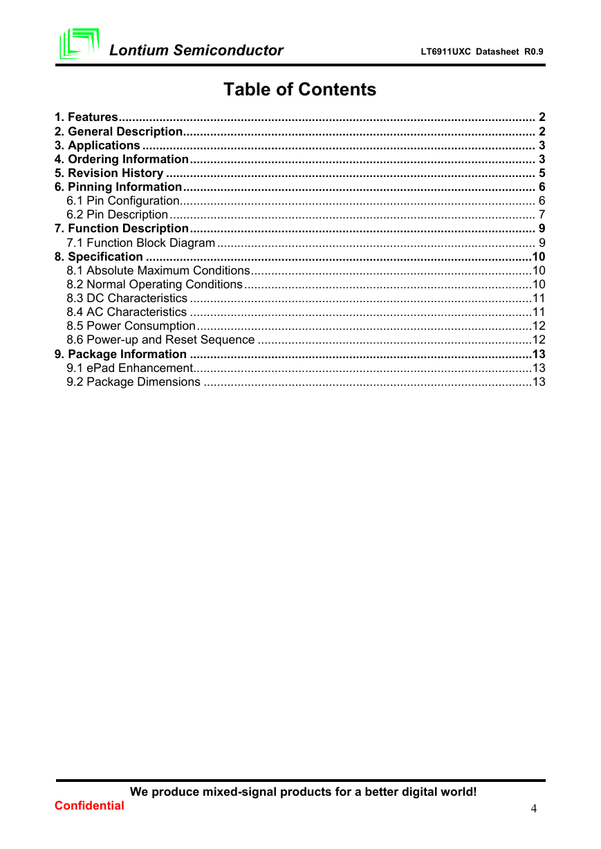
Table of Contents
1. Features ........................................................................................................................... 2
2. General Description ........................................................................................................ 2
3. Applications .................................................................................................................... 3
4. Ordering Information ...................................................................................................... 3
5. Revision History ............................................................................................................. 5
6. Pinning Information ........................................................................................................ 6
6.1 Pin Configuration......................................................................................................... 6
6.2 Pin Description ............................................................................................................ 7
7. Function Description ...................................................................................................... 9
7.1 Function Block Diagram .............................................................................................. 9
8. Specification ..................................................................................................................10
8.1 Absolute Maximum Conditions ...................................................................................10
8.2 Normal Operating Conditions .....................................................................................10
8.3 DC Characteristics .....................................................................................................11
8.4 AC Characteristics .....................................................................................................11
8.5 Power Consumption ...................................................................................................12
8.6 Power-up and Reset Sequence .................................................................................12
9. Package Information .....................................................................................................13
9.1 ePad Enhancement ....................................................................................................13
9.2 Package Dimensions .................................................................................................13
We produce mixed-signal products for a better digital world!
Confidential
4
�
Lontium Semiconductor
LT6911UXC Datasheet R0.9
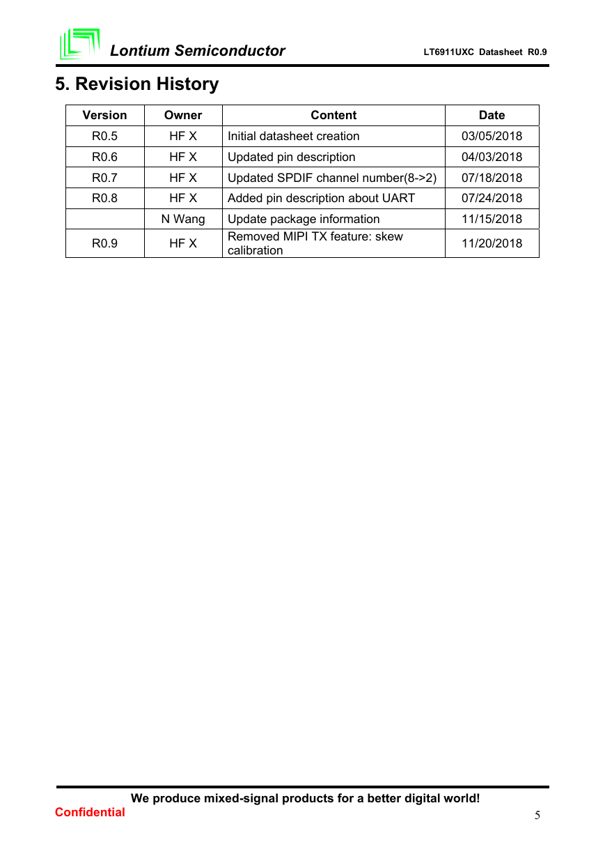
5. Revision History
Version
R0.5
R0.6
R0.7
R0.8
R0.9
Owner
HF X
HF X
HF X
HF X
N Wang
HF X
Content
Initial datasheet creation
Updated pin description
Updated SPDIF channel number(8->2)
Added pin description about UART
Update package information
Removed MIPI TX feature: skew
calibration
Date
03/05/2018
04/03/2018
07/18/2018
07/24/2018
11/15/2018
11/20/2018
We produce mixed-signal products for a better digital world!
Confidential
5
�
Lontium Semiconductor
LT6911UXC Datasheet R0.9
6. Pinning Information
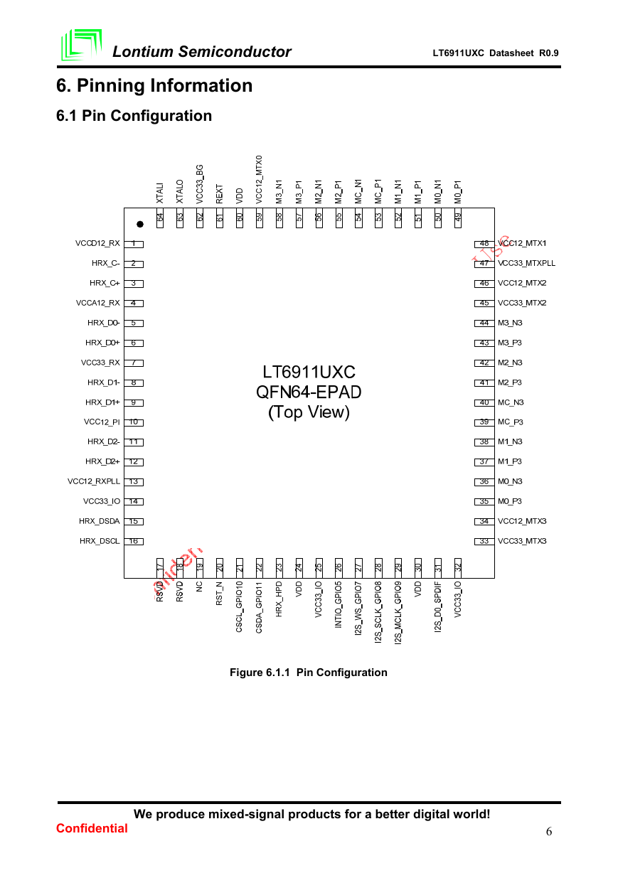
6.1 Pin Configuration
Figure 6.1.1 Pin Configuration
We produce mixed-signal products for a better digital world!
Confidential
6
�
Lontium Semiconductor
LT6911UXC Datasheet R0.9
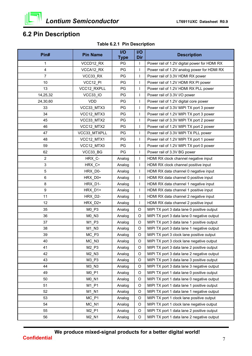
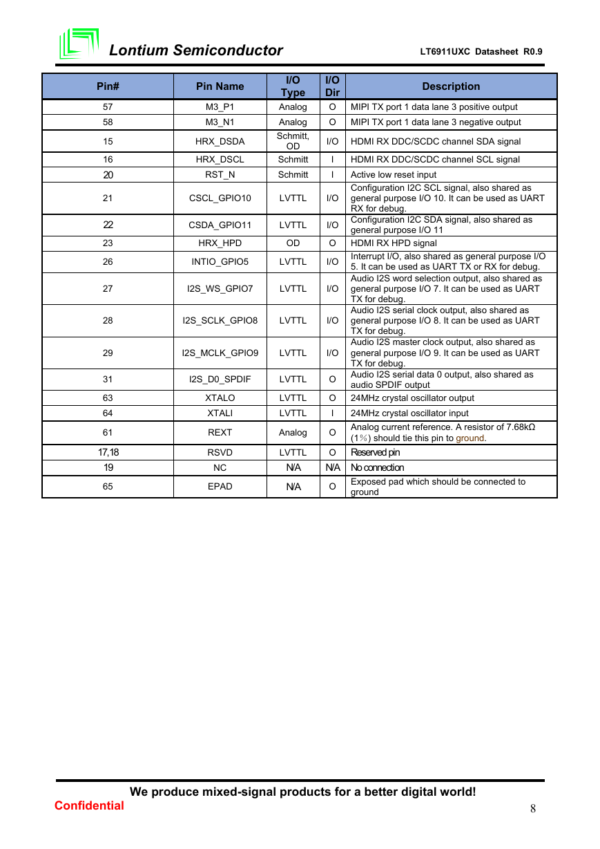
6.2 Pin Description
Table 6.2.1 Pin Description
Pin#
1
4
7
10
13
14,25,32
24,30,60
33
34
45
46
47
48
59
62
2
3
5
6
8
9
11
12
35
36
37
38
39
40
41
42
43
44
49
50
51
52
53
54
55
56
Pin Name
VCCD12_RX
VCCA12_RX
VCC33_RX
VCC12_PI
VCC12_RXPLL
VCC33_IO
VDD
VCC33_MTX3
VCC12_MTX3
VCC33_MTX2
VCC12_MTX2
VCC33_MTXPLL
VCC12_MTX1
VCC12_MTX0
VCC33_BG
HRX_C-
HRX_C+
HRX_D0-
HRX_D0+
HRX_D1-
HRX_D1+
HRX_D2-
HRX_D2+
M0_P3
M0_N3
M1_P3
M1_N3
MC_P3
MC_N3
M2_P3
M2_N3
M3_P3
M3_N3
M0_P1
M0_N1
M1_P1
M1_N1
MC_P1
MC_N1
M2_P1
M2_N1
I/O
Type
PG
PG
PG
PG
PG
PG
PG
PG
PG
PG
PG
PG
PG
PG
PG
Analog
Analog
Analog
Analog
Analog
Analog
Analog
Analog
Analog
Analog
Analog
Analog
Analog
Analog
Analog
Analog
Analog
Analog
Analog
Analog
Analog
Analog
Analog
Analog
Analog
Analog
Description
Power rail of 1.2V digital power for HDMI RX
Power rail of 1.2V analog power for HDMI RX
Power rail of 3.3V HDMI RX power
Power rail of 1.2V HDMI RX PI power
Power rail of 1.2V HDMI RX PLL power
Power rail of 3.3V I/O power
Power rail of 1.2V digital core power
Power rail of 3.3V MIPI TX port 3 power
Power rail of 1.2V MIPI TX port 3 power
Power rail of 3.3V MIPI TX port 2 power
Power rail of 1.2V MIPI TX port 2 power
Power rail of 3.3V MIPI TX PLL power
Power rail of 1.2V MIPI TX port 1 power
Power rail of 1.2V MIPI TX port 0 power
Power rail of 3.3V BG power
HDMI RX clock channel negative input
HDMI RX clock channel positive input
HDMI RX data channel 0 negative input
HDMI RX data channel 0 positive input
HDMI RX data channel 1 negative input
HDMI RX data channel 1 positive input
HDMI RX data channel 2 negative input
HDMI RX data channel 2 positive input
I/O
Dir
I
I
I
I
I
I
I
I
I
I
I
I
I
I
I
I
I
I
I
I
I
I
I
O MIPI TX port 3 data lane 0 positive output
O MIPI TX port 3 data lane 0 negative output
O MIPI TX port 3 data lane 1 positive output
O MIPI TX port 3 data lane 1 negative output
O MIPI TX port 3 clock lane positive output
O MIPI TX port 3 clock lane negative output
O MIPI TX port 3 data lane 2 positive output
O MIPI TX port 3 data lane 2 negative output
O MIPI TX port 3 data lane 3 positive output
O MIPI TX port 3 data lane 3 negative output
O MIPI TX port 1 data lane 0 positive output
O MIPI TX port 1 data lane 0 negative output
O MIPI TX port 1 data lane 1 positive output
O MIPI TX port 1 data lane 1 negative output
O MIPI TX port 1 clock lane positive output
O MIPI TX port 1 clock lane negative output
O MIPI TX port 1 data lane 2 positive output
O MIPI TX port 1 data lane 2 negative output
We produce mixed-signal products for a better digital world!
Confidential
7
�
LT6911UXC Datasheet R0.9
Lontium Semiconductor
Pin#
57
58
15
16
20
21
22
23
26
27
28
29
31
63
64
61
17,18
19
65
Pin Name
M3_P1
M3_N1
HRX_DSDA
HRX_DSCL
RST_N
I/O
Type
Analog
Analog
Schmitt,
OD
Schmitt
Schmitt
CSCL_GPIO10
LVTTL
I/O
CSDA_GPIO11
LVTTL
HRX_HPD
OD
INTIO_GPIO5
LVTTL
I2S_WS_GPIO7
LVTTL
I2S_SCLK_GPIO8
LVTTL
I2S_MCLK_GPIO9
LVTTL
I2S_D0_SPDIF
XTALO
XTALI
REXT
RSVD
NC
EPAD
LVTTL
LVTTL
LVTTL
Analog
LVTTL
N/A
N/A
I/O
Dir
O MIPI TX port 1 data lane 3 positive output
O MIPI TX port 1 data lane 3 negative output
Description
I/O HDMI RX DDC/SCDC channel SDA signal
I
I
HDMI RX DDC/SCDC channel SCL signal
Active low reset input
Configuration I2C SCL signal, also shared as
general purpose I/O 10. It can be used as UART
RX for debug.
I/O
I/O
I/O
general purpose I/O 11
HDMI RX HPD signal
I/O Configuration I2C SDA signal, also shared as
O
I/O Interrupt I/O, also shared as general purpose I/O
5. It can be used as UART TX or RX for debug.
Audio I2S word selection output, also shared as
general purpose I/O 7. It can be used as UART
TX for debug.
Audio I2S serial clock output, also shared as
general purpose I/O 8. It can be used as UART
TX for debug.
Audio I2S master clock output, also shared as
general purpose I/O 9. It can be used as UART
TX for debug.
Audio I2S serial data 0 output, also shared as
audio SPDIF output
24MHz crystal oscillator output
24MHz crystal oscillator input
Analog current reference. A resistor of 7.68kΩ
(1%) should tie this pin to ground.
Reserved pin
O
N/A No connection
O
Exposed pad which should be connected to
ground
O
O
I
O
We produce mixed-signal products for a better digital world!
Confidential
8
�




 2023年江西萍乡中考道德与法治真题及答案.doc
 2012年重庆南川中考生物真题及答案.doc
 2013年江西师范大学地理学综合及文艺理论基础考研真题.doc
 2020年四川甘孜小升初语文真题及答案I卷.doc
 2020年注册岩土工程师专业基础考试真题及答案.doc
 2023-2024学年福建省厦门市九年级上学期数学月考试题及答案.doc
 2021-2022学年辽宁省沈阳市大东区九年级上学期语文期末试题及答案.doc
 2022-2023学年北京东城区初三第一学期物理期末试卷及答案.doc
 2018上半年江西教师资格初中地理学科知识与教学能力真题及答案.doc
 2012年河北国家公务员申论考试真题及答案-省级.doc
 2020-2021学年江苏省扬州市江都区邵樊片九年级上学期数学第一次质量检测试题及答案.doc
 2022下半年黑龙江教师资格证中学综合素质真题及答案.doc