logo资料库

C6455 手册.pdf

第1页 / 共257页
第2页 / 共257页
第3页 / 共257页
第4页 / 共257页
第5页 / 共257页
第6页 / 共257页
第7页 / 共257页
第8页 / 共257页
资料共257页,剩余部分请下载后查看
TMS320C645x DSPSerial RapidIO (SRIO)
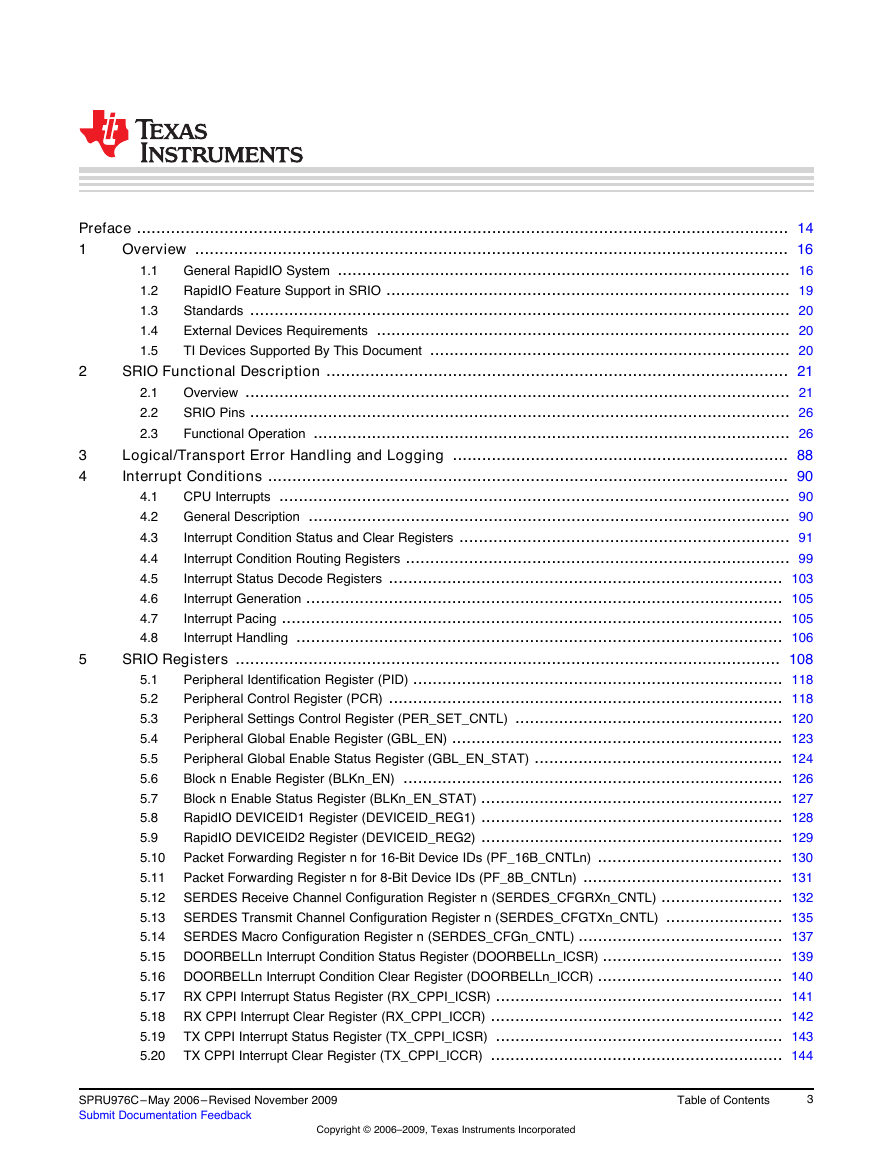
Table of Contents
Preface
1 Overview
1.1 General RapidIO System
1.1.1 RapidIO Architectural Hierarchy
1.1.2 RapidIO Interconnect Architecture
1.1.3 Physical Layer 1x/4x LP-Serial Specification
1.2 RapidIO Feature Support in SRIO
1.3 Standards
1.4 External Devices Requirements
1.5 TI Devices Supported By This Document
2 SRIO Functional Description
2.1 Overview
2.1.1 Peripheral Data Flow
2.1.2  SRIO Packets
2.1.2.1 Operation Sequence
2.1.2.2 Example Packet - Streaming Write
2.1.2.3 Control Symbols
2.1.2.4 SRIO Packet Type
2.2 SRIO Pins
2.3 Functional Operation
2.3.1 Component Block Diagram
2.3.2 SERDES Macro and Its Configurations
2.3.2.1 Enabling the PLL
2.3.2.2 Enabling the Receiver
2.3.2.3 Enabling the Transmitter
2.3.2.4 SERDES Configuration Example
2.3.3 Direct I/O Operation
2.3.3.1 Detailed Data Path Description
2.3.3.2 Direct I/O TX Operation
2.3.3.3 Direct I/O RX Operation
2.3.3.4 Reset and Power Down State
2.3.4 Message Passing
2.3.4.1 RX Operation
2.3.4.2 TX Operation
2.3.4.3 Reset and Power Down State
2.3.4.4 Message Passing Software Requirements
2.3.5 Maintenance
2.3.6 Doorbell Operation
2.3.7 Atomic Operations
2.3.8 Congestion Control
2.3.8.1 Detailed Description
2.3.9 Endianness
2.3.9.1 Translation for MMR space
2.3.9.2 Endian Conversion
2.3.10 Reset and Power Down
2.3.10.1 Reset and Power Down Summary
2.3.10.2 Enable and Enable Status Registers
2.3.10.3 Software Shutdown Details
2.3.11 Emulation
2.3.12 TX Buffers, Credit, and Packet Reordering
2.3.12.1 Multiple Ports With 1x Operation
2.3.12.2 Single Port With 1x or 4x Operation
2.3.12.3 Unavailable Outbound Credit
2.3.13 Initialization Example
2.3.13.1 Enabling the SRIO Peripheral
2.3.13.2 PLL, Ports, and Data Rate Initializations
2.3.13.3 Peripheral Initializations
2.3.14 Bootload Capability
2.3.14.1 Configuration and Operation
2.3.14.2 Bootload Data Movement
2.3.14.3 Device Wakeup
2.3.15 RX Multicast and Multiple DESTID Support
2.3.15.1 Discrete Multicast ID Support
2.3.15.2 Unlimited Multicast and DESTID Support
2.3.15.3 Daisy Chain Operation and Packet Forwarding
3 Logical/Transport Error Handling and Logging
4 Interrupt Conditions
4.1 CPU Interrupts
4.2 General Description
4.3 Interrupt Condition Status and Clear Registers
4.3.1 Doorbell Interrupt Condition Status and Clear Registers
4.3.2 CPPI Interrupt Condition Status and Clear Registers
4.3.3 LSU Interrupt Condition Status and Clear Registers
4.3.4 Error, Reset, and Special Event Interrupt Condition Status and Clear Registers
4.4 Interrupt Condition Routing Registers
4.4.1 Doorbell Interrupt Condition Routing Registers
4.4.1.1 CPPI Interrupt Condition Routing Registers
4.4.1.2 LSU Interrupt Condition Routing Registers
4.4.1.3 Error, Reset, and Special Event Interrupt Condition Routing Registers
4.5 Interrupt Status Decode Registers
4.6 Interrupt Generation
4.7 Interrupt Pacing
4.8 Interrupt Handling
5 SRIO Registers
5.1 Peripheral Identification Register (PID)
5.2 Peripheral Control Register (PCR)
5.3 Peripheral Settings Control Register (PER_SET_CNTL)
5.4 Peripheral Global Enable Register (GBL_EN)
5.5 Peripheral Global Enable Status Register (GBL_EN_STAT)
5.6 Block n Enable Register (BLKn_EN)
5.7 Block n Enable Status Register (BLKn_EN_STAT)
5.8 RapidIO DEVICEID1 Register (DEVICEID_REG1)
5.9 RapidIO DEVICEID2 Register (DEVICEID_REG2)
5.10 Packet Forwarding Register n for 16-Bit Device IDs (PF_16B_CNTLn)
5.11 Packet Forwarding Register n for 8-Bit Device IDs (PF_8B_CNTLn)
5.12 SERDES Receive Channel Configuration Register n (SERDES_CFGRXn_CNTL)
5.13 SERDES Transmit Channel Configuration Register n (SERDES_CFGTXn_CNTL)
5.14 SERDES Macro Configuration Register n (SERDES_CFGn_CNTL)
5.15 DOORBELLn Interrupt Condition Status Register (DOORBELLn_ICSR)
5.16 DOORBELLn Interrupt Condition Clear Register (DOORBELLn_ICCR)
5.17 RX CPPI Interrupt Status Register (RX_CPPI_ICSR)
5.18 RX CPPI Interrupt Clear Register (RX_CPPI_ICCR)
5.19 TX CPPI Interrupt Status Register (TX_CPPI_ICSR)
5.20 TX CPPI Interrupt Clear Register (TX_CPPI_ICCR)
5.21 LSU Interrupt Condition Status Register (LSU_ICSR)
5.22 LSU Interrupt Condition Clear Register (LSU_ICCR)
5.23 Error, Reset, and Special Event Interrupt Condition Status Register (ERR_RST_EVNT_ICSR)
5.24 Error, Reset, and Special Event Interrupt Condition Clear Register (ERR_RST_EVNT_ICCR)
5.25 DOORBELLn Interrupt Condition Routing Registers (DOORBELLn_ICRR and DOORBELLn_ICRR2)
5.26 RX CPPI Interrupt Condition Routing Registers (RX_CPPI_ICRR and RX_CPPI_ICRR2)
5.27 TX CPPI Interrupt Condition Routing Registers (TX_CPPI_ICRR and TX_CPPI_ICRR2)
5.28 LSU Interrupt Condition Routing Registers (LSU_ICRR0-LSU_ICRR3)
5.29 Error, Reset, and Special Event Interrupt Condition Routing Registers (ERR_RST_EVNT_ICRR, ERR_RST_EVNT_ICRR2, and ERR_RST_EVNT_ICRR3)
5.30 Interrupt Status Decode Register (INTDSTn_DECODE)
5.31 INTDSTn Interrupt Rate Control Register (INTDSTn_RATE_CNTL)
5.32 LSUn Control Register 0 (LSUn_REG0)
5.33 LSUn Control Register 1 (LSUn_REG1)
5.34 LSUn Control Register 2 (LSUn_REG2)
5.35 LSUn Control Register 3 (LSUn_REG3)
5.36 LSUn Control Register 4 (LSUn_REG4)
5.37 LSUn Control Register 5 (LSUn_REG5)
5.38 LSUn Control Register 6 (LSUn_REG6)
5.39 LSUn Congestion Control Flow Mask Register (LSUn_FLOW_MASKS)
5.40 Queue n Transmit DMA Head Descriptor Pointer Register (QUEUEn_TXDMA_HDP)
5.41 Queue n Transmit DMA Completion Pointer Register (QUEUEn_TXDMA_CP)
5.42 Queue n Receive DMA Head Descriptor Pointer Register (QUEUEn_RXDMA_HDP)
5.43 Queue n Receive DMA Completion Pointer Register (QUEUEn_RXDMA_CP)
5.44 Transmit Queue Teardown Register (TX_QUEUE_TEAR_DOWN)
5.45 Transmit CPPI Supported Flow Mask Registers (TX_CPPI_FLOW_MASKS[0-7])
5.46 Receive Queue Teardown Register (RX_QUEUE_TEAR_DOWN)
5.47 Receive CPPI Control Register (RX_CPPI_CNTL)
5.48 Transmit CPPI Weighted Round-Robin Control Registers (TX_QUEUE_CNTL[0-3])
5.49 Mailbox to Queue Mapping Registers (RXU_MAP_Ln and RXU_MAP_Hn)
5.50 Flow Control Table Entry Register n (FLOW_CNTLn)
5.51 Device Identity CAR (DEV_ID)
5.52 Device Information CAR (DEV_INFO)
5.53 Assembly Identity CAR (ASBLY_ID)
5.54 Assembly Information CAR (ASBLY_INFO)
5.55 Processing Element Features CAR (PE_FEAT)
5.56 Source Operations CAR (SRC_OP)
5.57 Destination Operations CAR (DEST_OP)
5.58 Processing Element Logical Layer Control CSR (PE_LL_CTL)
5.59 Local Configuration Space Base Address 0 CSR (LCL_CFG_HBAR)
5.60 Local Configuration Space Base Address 1 CSR (LCL_CFG_BAR)
5.61 Base Device ID CSR (BASE_ID)
5.62 Host Base Device ID Lock CSR (HOST_BASE_ID_LOCK)
5.63 Component Tag CSR (COMP_TAG)
5.64 1x/4x LP Serial Port Maintenance Block Header Register (SP_MB_HEAD)
5.65 Port Link Time-Out Control CSR (SP_LT_CTL)
5.66 Port Response Time-Out Control CSR (SP_RT_CTL)
5.67 Port General Control CSR (SP_GEN_CTL)
5.68 Port Link Maintenance Request CSR n (SPn_LM_REQ)
5.69 Port Link Maintenance Response CSR n (SPn_LM_RESP)
5.70 Port Local AckID Status CSR n (SPn_ACKID_STAT)
5.71 Port Error and Status CSR n (SPn_ERR_STAT)
5.72 Port Control CSR n (SPn_CTL)
5.73 Error Reporting Block Header Register (ERR_RPT_BH)
5.74 Logical/Transport Layer Error Detect CSR (ERR_DET)
5.75 Logical/Transport Layer Error Enable CSR (ERR_EN)
5.76 Logical/Transport Layer High Address Capture CSR (H_ADDR_CAPT)
5.77 Logical/Transport Layer Address Capture CSR (ADDR_CAPT)
5.78 Logical/Transport Layer Device ID Capture CSR (ID_CAPT)
5.79 Logical/Transport Layer Control Capture CSR (CTRL_CAPT)
5.80 Port-Write Target Device ID CSR (PW_TGT_ID)
5.81 Port Error Detect CSR n (SPn_ERR_DET)
5.82 Port Error Rate Enable CSR n (SPn_RATE_EN)
5.83 Port n Attributes Error Capture CSR 0 (SPn_ERR_ATTR_CAPT_DBG0)
5.84 Port n Error Capture CSR 1 (SPn_ERR_CAPT_DBG1)
5.85 Port n Error Capture CSR 2 (SPn_ERR_CAPT_DBG2)
5.86 Port n Error Capture CSR 3 (SPn_ERR_CAPT_DBG3)
5.87 Port n Error Capture CSR 4 (SPn_ERR_CAPT_DBG4)
5.88 Port Error Rate CSR n (SPn_ERR_RATE)
5.89 Port Error Rate Threshold CSR n (SPn_ERR_THRESH)
5.90 Port IP Discovery Timer for 4x Mode Register (SP_IP_DISCOVERY_TIMER)
5.91 Port IP Mode CSR (SP_IP_MODE)
5.92 Port IP Prescaler Register (IP_PRESCAL)
5.93 Port-Write-In Capture CSRs (SP_IP_PW_IN_CAPT[0-3])
5.94 Port Reset Option CSR n (SPn_RST_OPT)
5.95 Port Control Independent Register n (SPn_CTL_INDEP)
5.96 Port Silence Timer n Register (SPn_SILENCE_TIMER)
5.97 Port Multicast-Event Control Symbol Request Register n (SPn_MULT_EVNT_CS)
5.98 Port Control Symbol Transmit n Register (SPn_CS_TX)
Appendix A Examples
A.1 SRIO Initialization Example
A.2 LSU Programming Example
A.3 Message Passing Software
A.3.1 Initialization Example
A.3.2 Queue Mapping
A.3.3 RX Buffer Descriptor
A.3.4 TX Buffer Description
A.3.5 Start Message Passing
A.4 Interrupt Handling
Appendix B Software-Assisted Error Recovery
Appendix C Revision History
TMS320C645x DSP Serial RapidIO (SRIO) User's Guide Literature Number: SPRU976C May 2006–Revised November 2009
2 Copyright © 2006–2009, Texas Instruments Incorporated SPRU976C–May 2006– Revised November 2009 Submit Documentation Feedback
2 5 1.1 1.2 1.3 1.4 1.5 2.1 2.2 2.3 3 4 4.1 4.2 4.3 4.4 4.5 4.6 4.7 4.8 Preface ...................................................................................................................................... 14 Overview .......................................................................................................................... 16 1 General RapidIO System ............................................................................................. 16 RapidIO Feature Support in SRIO ................................................................................... 19 Standards ............................................................................................................... 20 External Devices Requirements ..................................................................................... 20 TI Devices Supported By This Document .......................................................................... 20 SRIO Functional Description ............................................................................................... 21 Overview ................................................................................................................ 21 SRIO Pins ............................................................................................................... 26 Functional Operation .................................................................................................. 26 Logical/Transport Error Handling and Logging ..................................................................... 88 Interrupt Conditions ........................................................................................................... 90 CPU Interrupts ......................................................................................................... 90 General Description ................................................................................................... 90 Interrupt Condition Status and Clear Registers .................................................................... 91 Interrupt Condition Routing Registers ............................................................................... 99 Interrupt Status Decode Registers ................................................................................. 103 Interrupt Generation .................................................................................................. 105 Interrupt Pacing ....................................................................................................... 105 Interrupt Handling .................................................................................................... 106 SRIO Registers ................................................................................................................ 108 Peripheral Identification Register (PID) ............................................................................ 118 5.1 Peripheral Control Register (PCR) ................................................................................. 118 5.2 Peripheral Settings Control Register (PER_SET_CNTL) ....................................................... 120 5.3 Peripheral Global Enable Register (GBL_EN) .................................................................... 123 5.4 Peripheral Global Enable Status Register (GBL_EN_STAT) ................................................... 124 5.5 Block n Enable Register (BLKn_EN) .............................................................................. 126 5.6 Block n Enable Status Register (BLKn_EN_STAT) .............................................................. 127 5.7 RapidIO DEVICEID1 Register (DEVICEID_REG1) .............................................................. 128 5.8 RapidIO DEVICEID2 Register (DEVICEID_REG2) .............................................................. 129 5.9 Packet Forwarding Register n for 16-Bit Device IDs (PF_16B_CNTLn) ...................................... 130 5.10 Packet Forwarding Register n for 8-Bit Device IDs (PF_8B_CNTLn) ......................................... 131 5.11 SERDES Receive Channel Configuration Register n (SERDES_CFGRXn_CNTL) ......................... 132 5.12 SERDES Transmit Channel Configuration Register n (SERDES_CFGTXn_CNTL) ........................ 135 5.13 SERDES Macro Configuration Register n (SERDES_CFGn_CNTL) .......................................... 137 5.14 5.15 DOORBELLn Interrupt Condition Status Register (DOORBELLn_ICSR) ..................................... 139 5.16 DOORBELLn Interrupt Condition Clear Register (DOORBELLn_ICCR) ...................................... 140 5.17 RX CPPI Interrupt Status Register (RX_CPPI_ICSR) ........................................................... 141 5.18 RX CPPI Interrupt Clear Register (RX_CPPI_ICCR) ............................................................ 142 TX CPPI Interrupt Status Register (TX_CPPI_ICSR) ........................................................... 143 5.19 TX CPPI Interrupt Clear Register (TX_CPPI_ICCR) ............................................................ 144 5.20 SPRU976C–May 2006– Revised November 2009 Submit Documentation Feedback Copyright © 2006–2009, Texas Instruments Incorporated Table of Contents 3
www.ti.com LSU Interrupt Condition Status Register (LSU_ICSR) .......................................................... 145 LSU Interrupt Condition Clear Register (LSU_ICCR) ........................................................... 148 Error, Reset, and Special Event Interrupt Condition Status Register (ERR_RST_EVNT_ICSR) .......... 149 Error, Reset, and Special Event Interrupt Condition Clear Register (ERR_RST_EVNT_ICCR) ........... 150 5.21 5.22 5.23 5.24 5.25 DOORBELLn Interrupt Condition Routing Registers (DOORBELLn_ICRR and DOORBELLn_ICRR2) ........................................................................................................................... 151 5.26 RX CPPI Interrupt Condition Routing Registers (RX_CPPI_ICRR and RX_CPPI_ICRR2) ................ 152 TX CPPI Interrupt Condition Routing Registers (TX_CPPI_ICRR and TX_CPPI_ICRR2) ................. 153 5.27 LSU Interrupt Condition Routing Registers (LSU_ICRR0-LSU_ICRR3) ...................................... 154 5.28 Error, Reset, and Special Event Interrupt Condition Routing Registers (ERR_RST_EVNT_ICRR, 5.29 ERR_RST_EVNT_ICRR2, and ERR_RST_EVNT_ICRR3) .................................................... 156 Interrupt Status Decode Register (INTDSTn_DECODE) ........................................................ 157 5.30 INTDSTn Interrupt Rate Control Register (INTDSTn_RATE_CNTL) .......................................... 161 5.31 LSUn Control Register 0 (LSUn_REG0) .......................................................................... 162 5.32 LSUn Control Register 1 (LSUn_REG1) .......................................................................... 163 5.33 LSUn Control Register 2 (LSUn_REG2) .......................................................................... 164 5.34 LSUn Control Register 3 (LSUn_REG3) .......................................................................... 165 5.35 LSUn Control Register 4 (LSUn_REG4) .......................................................................... 166 5.36 LSUn Control Register 5 (LSUn_REG5) .......................................................................... 167 5.37 LSUn Control Register 6 (LSUn_REG6) .......................................................................... 168 5.38 LSUn Congestion Control Flow Mask Register (LSUn_FLOW_MASKS) ..................................... 169 5.39 5.40 Queue n Transmit DMA Head Descriptor Pointer Register (QUEUEn_TXDMA_HDP) ..................... 171 5.41 Queue n Transmit DMA Completion Pointer Register (QUEUEn_TXDMA_CP) ............................. 172 5.42 Queue n Receive DMA Head Descriptor Pointer Register (QUEUEn_RXDMA_HDP) ..................... 173 5.43 Queue n Receive DMA Completion Pointer Register (QUEUEn_RXDMA_CP) ............................. 174 Transmit Queue Teardown Register (TX_QUEUE_TEAR_DOWN) ........................................... 175 5.44 Transmit CPPI Supported Flow Mask Registers (TX_CPPI_FLOW_MASKS[0-7]) .......................... 176 5.45 5.46 Receive Queue Teardown Register (RX_QUEUE_TEAR_DOWN) ........................................... 179 5.47 Receive CPPI Control Register (RX_CPPI_CNTL) .............................................................. 180 Transmit CPPI Weighted Round-Robin Control Registers (TX_QUEUE_CNTL[0-3]) ....................... 181 5.48 5.49 Mailbox to Queue Mapping Registers (RXU_MAP_Ln and RXU_MAP_Hn) ................................. 185 Flow Control Table Entry Register n (FLOW_CNTLn) .......................................................... 189 5.50 5.51 Device Identity CAR (DEV_ID) ..................................................................................... 190 5.52 Device Information CAR (DEV_INFO) ............................................................................. 191 Assembly Identity CAR (ASBLY_ID) ............................................................................... 192 5.53 Assembly Information CAR (ASBLY_INFO) ...................................................................... 193 5.54 Processing Element Features CAR (PE_FEAT) ................................................................. 194 5.55 Source Operations CAR (SRC_OP) ............................................................................... 196 5.56 5.57 Destination Operations CAR (DEST_OP) ......................................................................... 197 Processing Element Logical Layer Control CSR (PE_LL_CTL) ................................................ 198 5.58 Local Configuration Space Base Address 0 CSR (LCL_CFG_HBAR) ........................................ 199 5.59 Local Configuration Space Base Address 1 CSR (LCL_CFG_BAR) .......................................... 199 5.60 Base Device ID CSR (BASE_ID) ................................................................................... 200 5.61 5.62 Host Base Device ID Lock CSR (HOST_BASE_ID_LOCK) .................................................... 201 5.63 Component Tag CSR (COMP_TAG) .............................................................................. 202 1x/4x LP Serial Port Maintenance Block Header Register (SP_MB_HEAD) ................................. 203 5.64 Port Link Time-Out Control CSR (SP_LT_CTL) .................................................................. 204 5.65 Port Response Time-Out Control CSR (SP_RT_CTL) .......................................................... 205 5.66 Port General Control CSR (SP_GEN_CTL) ...................................................................... 206 5.67 4 Contents Copyright © 2006–2009, Texas Instruments Incorporated SPRU976C–May 2006– Revised November 2009 Submit Documentation Feedback
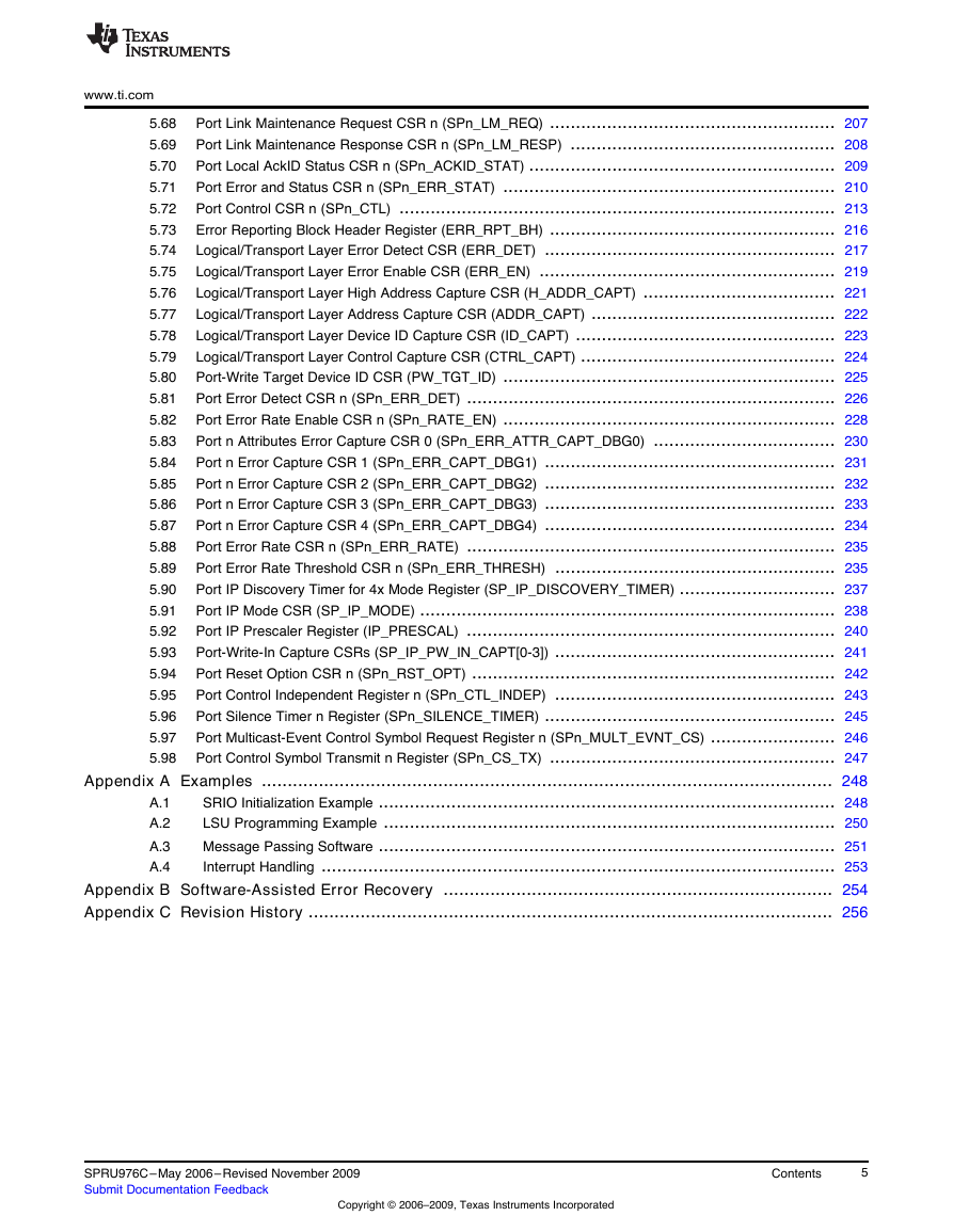
www.ti.com 5.68 5.69 5.70 5.71 5.72 5.73 5.74 5.75 5.76 5.77 5.78 5.79 5.80 5.81 5.82 5.83 5.84 5.85 5.86 5.87 5.88 5.89 5.90 5.91 5.92 5.93 5.94 5.95 5.96 5.97 5.98 Port Link Maintenance Request CSR n (SPn_LM_REQ) ....................................................... 207 Port Link Maintenance Response CSR n (SPn_LM_RESP) ................................................... 208 Port Local AckID Status CSR n (SPn_ACKID_STAT) ........................................................... 209 Port Error and Status CSR n (SPn_ERR_STAT) ................................................................ 210 Port Control CSR n (SPn_CTL) .................................................................................... 213 Error Reporting Block Header Register (ERR_RPT_BH) ....................................................... 216 Logical/Transport Layer Error Detect CSR (ERR_DET) ........................................................ 217 Logical/Transport Layer Error Enable CSR (ERR_EN) ......................................................... 219 Logical/Transport Layer High Address Capture CSR (H_ADDR_CAPT) ..................................... 221 Logical/Transport Layer Address Capture CSR (ADDR_CAPT) ............................................... 222 Logical/Transport Layer Device ID Capture CSR (ID_CAPT) .................................................. 223 Logical/Transport Layer Control Capture CSR (CTRL_CAPT) ................................................. 224 Port-Write Target Device ID CSR (PW_TGT_ID) ................................................................ 225 Port Error Detect CSR n (SPn_ERR_DET) ....................................................................... 226 Port Error Rate Enable CSR n (SPn_RATE_EN) ................................................................ 228 Port n Attributes Error Capture CSR 0 (SPn_ERR_ATTR_CAPT_DBG0) ................................... 230 Port n Error Capture CSR 1 (SPn_ERR_CAPT_DBG1) ........................................................ 231 Port n Error Capture CSR 2 (SPn_ERR_CAPT_DBG2) ........................................................ 232 Port n Error Capture CSR 3 (SPn_ERR_CAPT_DBG3) ........................................................ 233 Port n Error Capture CSR 4 (SPn_ERR_CAPT_DBG4) ........................................................ 234 Port Error Rate CSR n (SPn_ERR_RATE) ....................................................................... 235 Port Error Rate Threshold CSR n (SPn_ERR_THRESH) ...................................................... 235 Port IP Discovery Timer for 4x Mode Register (SP_IP_DISCOVERY_TIMER) .............................. 237 Port IP Mode CSR (SP_IP_MODE) ................................................................................ 238 Port IP Prescaler Register (IP_PRESCAL) ....................................................................... 240 Port-Write-In Capture CSRs (SP_IP_PW_IN_CAPT[0-3]) ...................................................... 241 Port Reset Option CSR n (SPn_RST_OPT) ...................................................................... 242 Port Control Independent Register n (SPn_CTL_INDEP) ...................................................... 243 Port Silence Timer n Register (SPn_SILENCE_TIMER) ........................................................ 245 Port Multicast-Event Control Symbol Request Register n (SPn_MULT_EVNT_CS) ........................ 246 Port Control Symbol Transmit n Register (SPn_CS_TX) ....................................................... 247 Appendix A Examples .............................................................................................................. 248 SRIO Initialization Example ........................................................................................ 248 LSU Programming Example ....................................................................................... 250 Message Passing Software ........................................................................................ 251 Interrupt Handling ................................................................................................... 253 Appendix B Software-Assisted Error Recovery ........................................................................... 254 Appendix C Revision History ..................................................................................................... 256 A.1 A.2 A.3 A.4 SPRU976C–May 2006– Revised November 2009 Submit Documentation Feedback Copyright © 2006–2009, Texas Instruments Incorporated Contents 5
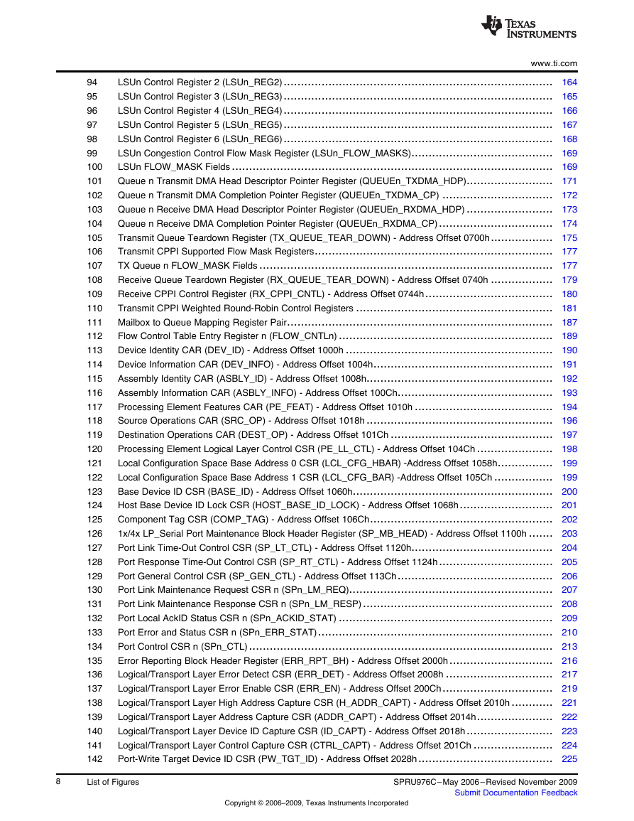
List of Figures www.ti.com RapidIO Architectural Hierarchy......................................................................................... 17 RapidIO Interconnect Architecture ...................................................................................... 18 Serial RapidIO Device-to-Device Interface Diagrams ................................................................ 19 SRIO Peripheral Block Diagram......................................................................................... 22 Operation Sequence ...................................................................................................... 23 1x/4x RapidIO Packet Data Stream (Streaming-Write Class) ....................................................... 24 Serial RapidIO Control Symbol Format................................................................................. 24 SRIO Component Block Diagram ....................................................................................... 27 SERDES Macro Configuration Register 0 (SERDES_CFG0_CNTL)............................................... 28 SERDES Receive Channel Configuration Register n (SERDES_CFGRXn_CNTL).............................. 32 SERDES Transmit Channel Configuration Register n (SERDES_CFGTXn_CNTL) ............................. 34 Load/Store Registers for RapidIO (Address Offset: LSU1 400h-418h, LSU2 420h-438h, LSU3 440h-458h, LSU4 460h-478h) ........................................................................................... 36 LSU Registers Timing..................................................................................................... 39 Example Burst NWRITE_R .............................................................................................. 40 Load/Store Module Data Flow Diagram ................................................................................ 41 CPPI RX Scheme for RapidIO........................................................................................... 45 Message Request Packet ................................................................................................ 46 Mailbox to Queue Mapping Register Pair .............................................................................. 47 RX Buffer Descriptor Fields .............................................................................................. 48 RX CPPI Mode Explanation.............................................................................................. 50 CPPI Boundary Diagram ................................................................................................. 52 TX Buffer Descriptor Fields .............................................................................................. 53 Weighted Round-Robin Programming Registers - Address Offset 7E0h-7ECh .................................. 56 RX Buffer Descriptors..................................................................................................... 63 TX Buffer Descriptors ..................................................................................................... 64 Doorbell Operation ........................................................................................................ 65 Flow Control Table Entry Registers - Address Offset 0900h-093Ch ............................................... 68 Transmit Source Flow Control Masks .................................................................................. 69 Fields Within Each Flow Mask........................................................................................... 69 Configuration Bus Example .............................................................................................. 70 DMA Example.............................................................................................................. 71 GBL_EN (Address 0030h) ............................................................................................... 73 GBL_EN_STAT (Address 0034h) ....................................................................................... 73 BLK0_EN (Address 0038h) .............................................................................................. 75 BLK0_EN_STAT (Address 003Ch) ..................................................................................... 75 BLK1_EN (Address 0040h) .............................................................................................. 75 BLK1_EN_STAT (Address 0044h)...................................................................................... 75 BLK8_EN (Address 0078h) .............................................................................................. 75 BLK8_EN_STAT (Address 007Ch) ..................................................................................... 75 Peripheral Control Register (PCR) - Address Offset 0004h ......................................................... 77 Bootload Operation........................................................................................................ 82 Logical/Transport Layer Error Detect CSR (ERR_DET) ............................................................. 88 RapidIO DOORBELL Packet for Interrupt Use ........................................................................ 90 Doorbell 0 Interrupt Condition Status and Clear Registers .......................................................... 92 Doorbell 1 Interrupt Condition Status and Clear Registers .......................................................... 92 Doorbell 2 Interrupt Condition Status and Clear Registers .......................................................... 93 1 2 3 4 5 6 7 8 9 10 11 12 13 14 15 16 17 18 19 20 21 22 23 24 25 26 27 28 29 30 31 32 33 34 35 36 37 38 39 40 41 42 43 44 45 46 6 List of Figures Copyright © 2006–2009, Texas Instruments Incorporated SPRU976C–May 2006– Revised November 2009 Submit Documentation Feedback
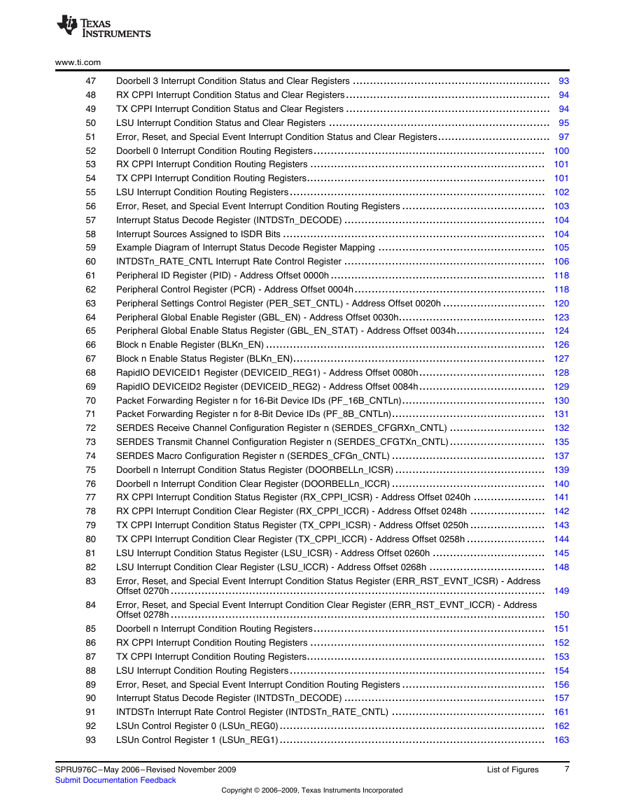
www.ti.com 47 48 49 50 51 52 53 54 55 56 57 58 59 60 61 62 63 64 65 66 67 68 69 70 71 72 73 74 75 76 77 78 79 80 81 82 83 84 85 86 87 88 89 90 91 92 93 Doorbell 3 Interrupt Condition Status and Clear Registers .......................................................... 93 RX CPPI Interrupt Condition Status and Clear Registers............................................................ 94 TX CPPI Interrupt Condition Status and Clear Registers ............................................................ 94 LSU Interrupt Condition Status and Clear Registers ................................................................. 95 Error, Reset, and Special Event Interrupt Condition Status and Clear Registers................................. 97 Doorbell 0 Interrupt Condition Routing Registers.................................................................... 100 RX CPPI Interrupt Condition Routing Registers ..................................................................... 101 TX CPPI Interrupt Condition Routing Registers...................................................................... 101 LSU Interrupt Condition Routing Registers........................................................................... 102 Error, Reset, and Special Event Interrupt Condition Routing Registers .......................................... 103 Interrupt Status Decode Register (INTDSTn_DECODE) ........................................................... 104 Interrupt Sources Assigned to ISDR Bits ............................................................................. 104 Example Diagram of Interrupt Status Decode Register Mapping ................................................. 105 INTDSTn_RATE_CNTL Interrupt Rate Control Register ........................................................... 106 Peripheral ID Register (PID) - Address Offset 0000h ............................................................... 118 Peripheral Control Register (PCR) - Address Offset 0004h........................................................ 118 Peripheral Settings Control Register (PER_SET_CNTL) - Address Offset 0020h .............................. 120 Peripheral Global Enable Register (GBL_EN) - Address Offset 0030h........................................... 123 Peripheral Global Enable Status Register (GBL_EN_STAT) - Address Offset 0034h.......................... 124 Block n Enable Register (BLKn_EN) .................................................................................. 126 Block n Enable Status Register (BLKn_EN).......................................................................... 127 RapidIO DEVICEID1 Register (DEVICEID_REG1) - Address Offset 0080h..................................... 128 RapidIO DEVICEID2 Register (DEVICEID_REG2) - Address Offset 0084h..................................... 129 Packet Forwarding Register n for 16-Bit Device IDs (PF_16B_CNTLn).......................................... 130 Packet Forwarding Register n for 8-Bit Device IDs (PF_8B_CNTLn)............................................. 131 SERDES Receive Channel Configuration Register n (SERDES_CFGRXn_CNTL) ............................ 132 SERDES Transmit Channel Configuration Register n (SERDES_CFGTXn_CNTL)............................ 135 SERDES Macro Configuration Register n (SERDES_CFGn_CNTL) ............................................. 137 Doorbell n Interrupt Condition Status Register (DOORBELLn_ICSR) ............................................ 139 Doorbell n Interrupt Condition Clear Register (DOORBELLn_ICCR) ............................................. 140 RX CPPI Interrupt Condition Status Register (RX_CPPI_ICSR) - Address Offset 0240h ..................... 141 RX CPPI Interrupt Condition Clear Register (RX_CPPI_ICCR) - Address Offset 0248h ...................... 142 TX CPPI Interrupt Condition Status Register (TX_CPPI_ICSR) - Address Offset 0250h ...................... 143 TX CPPI Interrupt Condition Clear Register (TX_CPPI_ICCR) - Address Offset 0258h ....................... 144 LSU Interrupt Condition Status Register (LSU_ICSR) - Address Offset 0260h ................................. 145 LSU Interrupt Condition Clear Register (LSU_ICCR) - Address Offset 0268h .................................. 148 Error, Reset, and Special Event Interrupt Condition Status Register (ERR_RST_EVNT_ICSR) - Address Offset 0270h .............................................................................................................. 149 Error, Reset, and Special Event Interrupt Condition Clear Register (ERR_RST_EVNT_ICCR) - Address Offset 0278h .............................................................................................................. 150 Doorbell n Interrupt Condition Routing Registers.................................................................... 151 RX CPPI Interrupt Condition Routing Registers ..................................................................... 152 TX CPPI Interrupt Condition Routing Registers...................................................................... 153 LSU Interrupt Condition Routing Registers........................................................................... 154 Error, Reset, and Special Event Interrupt Condition Routing Registers .......................................... 156 Interrupt Status Decode Register (INTDSTn_DECODE) ........................................................... 157 INTDSTn Interrupt Rate Control Register (INTDSTn_RATE_CNTL) ............................................. 161 LSUn Control Register 0 (LSUn_REG0).............................................................................. 162 LSUn Control Register 1 (LSUn_REG1).............................................................................. 163 SPRU976C–May 2006– Revised November 2009 Submit Documentation Feedback Copyright © 2006–2009, Texas Instruments Incorporated List of Figures 7
www.ti.com LSUn Control Register 2 (LSUn_REG2).............................................................................. 164 94 LSUn Control Register 3 (LSUn_REG3).............................................................................. 165 95 LSUn Control Register 4 (LSUn_REG4).............................................................................. 166 96 LSUn Control Register 5 (LSUn_REG5).............................................................................. 167 97 LSUn Control Register 6 (LSUn_REG6).............................................................................. 168 98 LSUn Congestion Control Flow Mask Register (LSUn_FLOW_MASKS)......................................... 169 99 LSUn FLOW_MASK Fields ............................................................................................. 169 100 Queue n Transmit DMA Head Descriptor Pointer Register (QUEUEn_TXDMA_HDP)......................... 171 101 Queue n Transmit DMA Completion Pointer Register (QUEUEn_TXDMA_CP) ................................ 172 102 Queue n Receive DMA Head Descriptor Pointer Register (QUEUEn_RXDMA_HDP) ......................... 173 103 Queue n Receive DMA Completion Pointer Register (QUEUEn_RXDMA_CP)................................. 174 104 Transmit Queue Teardown Register (TX_QUEUE_TEAR_DOWN) - Address Offset 0700h.................. 175 105 Transmit CPPI Supported Flow Mask Registers..................................................................... 177 106 TX Queue n FLOW_MASK Fields ..................................................................................... 177 107 Receive Queue Teardown Register (RX_QUEUE_TEAR_DOWN) - Address Offset 0740h .................. 179 108 Receive CPPI Control Register (RX_CPPI_CNTL) - Address Offset 0744h..................................... 180 109 Transmit CPPI Weighted Round-Robin Control Registers ......................................................... 181 110 111 Mailbox to Queue Mapping Register Pair............................................................................. 187 Flow Control Table Entry Register n (FLOW_CNTLn) .............................................................. 189 112 Device Identity CAR (DEV_ID) - Address Offset 1000h ............................................................ 190 113 Device Information CAR (DEV_INFO) - Address Offset 1004h.................................................... 191 114 Assembly Identity CAR (ASBLY_ID) - Address Offset 1008h...................................................... 192 115 Assembly Information CAR (ASBLY_INFO) - Address Offset 100Ch............................................. 193 116 Processing Element Features CAR (PE_FEAT) - Address Offset 1010h ........................................ 194 117 Source Operations CAR (SRC_OP) - Address Offset 1018h ...................................................... 196 118 Destination Operations CAR (DEST_OP) - Address Offset 101Ch ............................................... 197 119 Processing Element Logical Layer Control CSR (PE_LL_CTL) - Address Offset 104Ch ...................... 198 120 Local Configuration Space Base Address 0 CSR (LCL_CFG_HBAR) -Address Offset 1058h................ 199 121 Local Configuration Space Base Address 1 CSR (LCL_CFG_BAR) -Address Offset 105Ch ................. 199 122 Base Device ID CSR (BASE_ID) - Address Offset 1060h.......................................................... 200 123 Host Base Device ID Lock CSR (HOST_BASE_ID_LOCK) - Address Offset 1068h........................... 201 124 Component Tag CSR (COMP_TAG) - Address Offset 106Ch..................................................... 202 125 1x/4x LP_Serial Port Maintenance Block Header Register (SP_MB_HEAD) - Address Offset 1100h ....... 203 126 Port Link Time-Out Control CSR (SP_LT_CTL) - Address Offset 1120h......................................... 204 127 Port Response Time-Out Control CSR (SP_RT_CTL) - Address Offset 1124h................................. 205 128 Port General Control CSR (SP_GEN_CTL) - Address Offset 113Ch............................................. 206 129 Port Link Maintenance Request CSR n (SPn_LM_REQ)........................................................... 207 130 Port Link Maintenance Response CSR n (SPn_LM_RESP) ....................................................... 208 131 Port Local AckID Status CSR n (SPn_ACKID_STAT) .............................................................. 209 132 Port Error and Status CSR n (SPn_ERR_STAT).................................................................... 210 133 Port Control CSR n (SPn_CTL)........................................................................................ 213 134 Error Reporting Block Header Register (ERR_RPT_BH) - Address Offset 2000h.............................. 216 135 Logical/Transport Layer Error Detect CSR (ERR_DET) - Address Offset 2008h ............................... 217 136 Logical/Transport Layer Error Enable CSR (ERR_EN) - Address Offset 200Ch................................ 219 137 Logical/Transport Layer High Address Capture CSR (H_ADDR_CAPT) - Address Offset 2010h ............ 221 138 Logical/Transport Layer Address Capture CSR (ADDR_CAPT) - Address Offset 2014h...................... 222 139 Logical/Transport Layer Device ID Capture CSR (ID_CAPT) - Address Offset 2018h......................... 223 140 Logical/Transport Layer Control Capture CSR (CTRL_CAPT) - Address Offset 201Ch ....................... 224 141 Port-Write Target Device ID CSR (PW_TGT_ID) - Address Offset 2028h....................................... 225 142 8 List of Figures Copyright © 2006–2009, Texas Instruments Incorporated SPRU976C–May 2006– Revised November 2009 Submit Documentation Feedback
分享到:
收藏