Bluetooth® Measurement
Fundamentals
Application Note
Bluetooth® wireless technology is
an open specification for a wireless
personal area network (PAN). It
provides limited range wireless
connectivity for voice and data
transmissions between information
appliances. Bluetooth wireless
technology eliminates the need for
interconnecting cables. Unique for
most wireless communications
systems, Bluetooth enables ad hoc
networking among devices, without
the need for infrastructure such as
base stations or access points.
Named after a tenth-century Danish
King, Bluetooth invokes images of
Viking conquests and plundering;
notwithstanding this, the good King
Harald Blatand is credited with
uniting Denmark and Norway during
his reign. Similarly today, Bluetooth
unites devices through its wireless
communications link.
Bluetooth wireless technology allows
seamless interconnectivity among
devices. Imagine your computer
synchronizing files and databases
with your personal digital assistant
(PDA), simply because you carried
the PDA into the vicinity of the PC.
Wireless headsets can simplify
hands-free operation of mobile
phones as a convenient and safe way
to talk while driving. The potential
of this technology is limitless when
one considers the growing sector of
information appliances that would
benefit from wireless connectivity. This
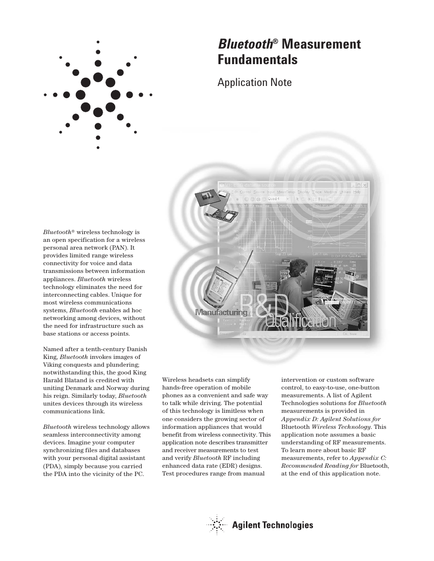
application note describes transmitter
and receiver measurements to test
and verify Bluetooth RF including
enhanced data rate (EDR) designs.
Test procedures range from manual
intervention or custom software
control, to easy-to-use, one-button
measurements. A list of Agilent
Technologies solutions for Bluetooth
measurements is provided in
Appendix D: Agilent Solutions for
Bluetooth Wireless Technology. This
application note assumes a basic
understanding of RF measurements.
To learn more about basic RF
measurements, refer to Appendix C:
Recommended Reading for Bluetooth,
at the end of this application note.
�
Table of Contents
Introduction . . . . . . . . . . . . . . . . . . . . .1
1. Basic Concepts of Bluetooth . . . . .3
1.1 Bluetooth radio unit . . . . . . . . . . . . . . .4
1.2 Bluetooth link control unit and link
management . . . . . . . . . . . . . . . . . . . . .6
1.3 Bluetooth RF test suite structure . . .8
2. Transmitter Measurements . . . . .10
2.1 Test conditions and setup . . . . . . . . .10
2.2 Power tests . . . . . . . . . . . . . . . . . . . . .13
2.3 Transmit output spectrum . . . . . . . . .16
2.4 Modulation tests . . . . . . . . . . . . . . . .18
2.5 Timing tests . . . . . . . . . . . . . . . . . . . . .23
3. Transceiver Measurements . . . . .26
3.1 EDR in-band spurious emissions . . .26
4. Receiver Measurements . . . . . . . .27
4.1 Test conditions and setup . . . . . . . . .27
4.2 Sensitivity - single-slot packets . . . .30
4.3 Sensitivity - multi-slot packets . . . . .31
4.4 EDR sensitivity . . . . . . . . . . . . . . . . . .31
4.5 EDR BER floor performance . . . . . . .31
4.6 Carrier-to-interference (C/I)
performance . . . . . . . . . . . . . . . . . . . .32
4.7 EDR carrier-to-interference (C/I)
performance . . . . . . . . . . . . . . . . . . . .32
4.8 Blocking performance . . . . . . . . . . . .33
4.9 Intermodulation performance . . . . . .33
4.10 Maximum input level . . . . . . . . . . . . .33
4.11 EDR maximum input level . . . . . . . . .33
5. Power Supply Measurements . . .34
Appendix A: Glossary . . . . . . . . . . . . . . . .35
Appendix B: Symbols and Acronyms . . .36
Appendix C: Recommended Reading . . .37
Appendix D: Agilent Solutions for
Bluetooth . . . . . . . . . . . . . . . . . . . . . .38
Appendix E: References . . . . . . . . . . . . . .39
2
�
1. Basic Concepts of Bluetooth
Bluetooth, in its most elementary
form, is defined as a global
specification for wireless connectivity.
Because it is intended to replace
cables, cost must be low and operation
must be intuitive and robust. These
requirements for Bluetooth create
many challenges. Bluetooth meets
these challenges by several means.
The radio unit employs frequency
hopping spread spectrum (FHSS),
and the design emphasis is on very
low power, extremely low cost,
and robust operation in the
uncoordinated, interference-dominated
RF environment of the industrial,
scientific, and medical (ISM) radio
band.
A wide variety of Bluetooth radio
block diagrams are in use. For
transmission, these range from direct
voltage controlled oscillator (VCO)
modulation to IQ mixing at the final
radio frequency (RF.) In the receiver, a
conventional frequency discriminator
or IQ down-conversion combined
with analog-to-digital conversion is
noted.
While many options can satisfy the
Bluetooth radio specifications, each
will have its own characteristics
if not operating correctly. The
Bluetooth system consists of a radio
unit, a baseband link control unit,
and link management software. It
also includes higher-level software
utilities that focus on interoperability
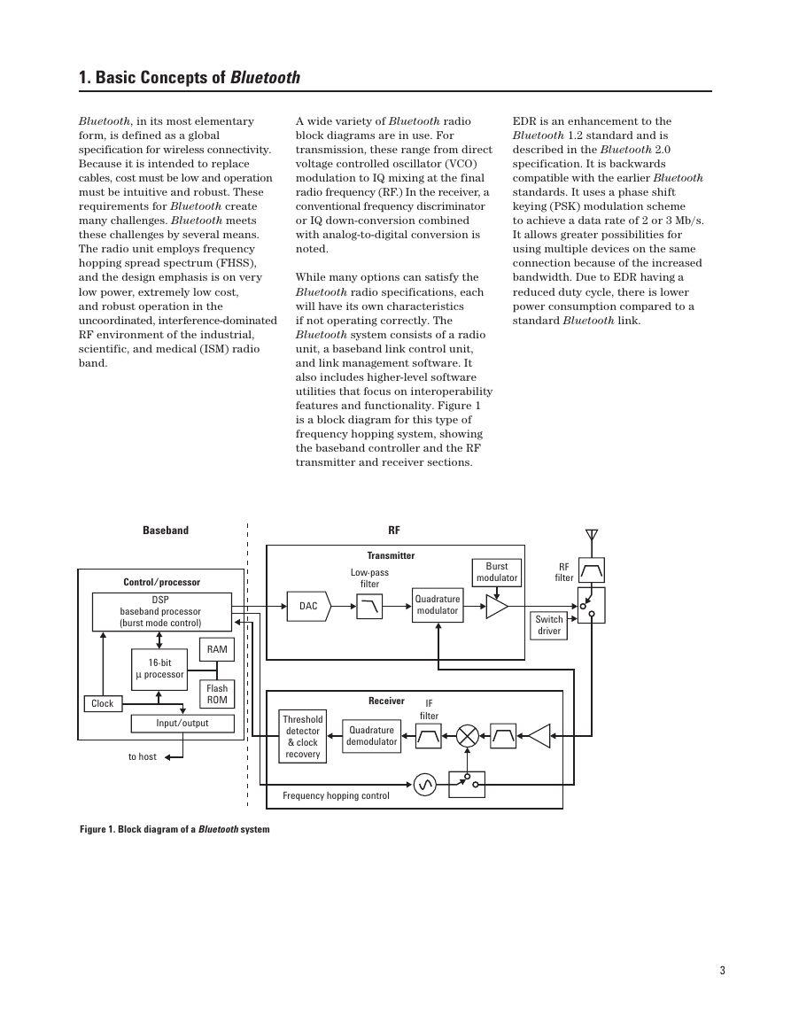
features and functionality. Figure 1
is a block diagram for this type of
frequency hopping system, showing
the baseband controller and the RF
transmitter and receiver sections.
EDR is an enhancement to the
Bluetooth 1.2 standard and is
described in the Bluetooth 2.0
specification. It is backwards
compatible with the earlier Bluetooth
standards. It uses a phase shift
keying (PSK) modulation scheme
to achieve a data rate of 2 or 3 Mb/s.
It allows greater possibilities for
using multiple devices on the same
connection because of the increased
bandwidth. Due to EDR having a
reduced duty cycle, there is lower
power consumption compared to a
standard Bluetooth link.
Baseband
Control/processor
DSP
baseband processor
(burst mode control)
16-bit
µ processor
RAM
Flash
ROM
Input/output
to host
Clock
Figure 1. Block diagram of a Bluetooth system
RF
Transmitter
Low-pass
filter
DAC
Quadrature
modulator
Burst
modulator
RF
filter
Switch
driver
Receiver
IF
filter
Quadrature
demodulator
Threshold
detector
& clock
recovery
Frequency hopping control
3
�
1.1 Bluetooth radio unit
The Bluetooth radio unit is shown
in Figure 1 as the transmitter and
receiver sections of the block
diagram. The transmitter up-converts
the baseband information to the
frequency-modulated carrier.
Frequency hopping and bursting are
performed at this level. Conversely,
the receiver down-converts and
demodulates the RF signal. Table 1
summarizes some of the key RF
characteristics of Bluetooth.
The Bluetooth channels are each
1 MHz wide. The frequency hopping
occurs over the 79 channels.
Figure 2 depicts the frequency
hopping channels, divided by
geographic regions.
The modulation in a standard
Bluetooth system is Gaussian
frequency shift keying (GFSK) this
gives a gross air data rate of 1 Mb/s.
This is a digital modulation format
in which the modulated carrier
shifts between two frequencies
representing a “1” and a “0”. As a
result, GFSK provides one bit of data
per symbol. Figure 3 is an example
of GFSK modulation illustrating
the two discrete frequencies.
Unlike many other forms of digital
modulation, such as GSM, amplitude
and phase are not of primary concern
in this type of modulation scheme.
Table 1. Key Bluetooth RF characteristics
Characteristic
Carrier frequency1
Modulation
Specification
2400 to 2483.5 MHz (ISM radio band)
Standard 0.5 BT Gaussian-filtered 2FSK at 1 Msymbol/s
Modulation index: 0.28 to 0.35 (0.32 nominal)
0.4 BT π/4-DQPSK at 2 Msymbol/s
0.4 BT 8DPSK at 3 Msymbol/s
1600 hops/s (in normal operation)2
1 MHz channel spacing
1) page hopping sequence
2) page response sequence
3) inquiry sequence
4) inquiry response sequence
5) channel hopping sequence
The first four are restricted hopping sequences used
during connection setup. The normal channel hopping
sequence is pseudorandom based on the master clock
value and device address.
Power class 1: 1 mW (0 dBm) to 100 mW (20 dBm)
Hopping
Transmit power
Operating range
Maximum data throughput
Power class 2: 0.25 mW (–6 dBm) to 2.5 mW (+4 dBm)
Power class 3: 1 mW (0 dBm) max power
10 cm to 10 m (100 m with power class 1)
The asynchronous channel can support an asymmetric
ink of maximally 721 kb/s in either direction while
permitting 57.6 kb/s in the return direction,
or a 432.6 kb/s symmetric link. EDR 3 Mb/s has a
real data throughput of 2.1 Mb/s
Notes
f = 2402 + k MHz, k = 0, 1, 2...,78
Digital FM scheme
The peak frequency deviation allowed is 175 kHz
The channel hopping sequence is designed to visit each
frequency regularly and with roughly equal probability.
The system has five different hopping sequences.
It has a periodicity of 23 hours and 18 minutes.
Class 1 power control:
+4 to +20 dBm (required)
–30 to +4 dBm (optional)
Class 2 power control:
–30 to 0 dBm (optional)
Class 3 power control:
–30 to 0 dBm (optional)
Range depends on amount of interference
Data throughput is lower than the 1 Msymbol/s rate as
a result of the overhead, which is inherent in the protocol
1. The Bluetooth specification includes a special frequency hopping pattern to provide provisions for compliance with national limitations such as
those in France. The frequency range for France is 2.4454 to 2.4835 GHz and the corresponding RF channels are f = 2454 + k MHz, k = 0,...,22.
2. Hop speed may vary, depending on packet length.
4
�
As an enhancement to the Bluetooth
standard, EDR uses different
modulation schemes so that data
can be sent at higher transmission
rates. There are two different types
of modulation that EDR utilizes,
π/4-DQPSK for 2 Mb/s and 8DPSK for
3 Mb/s gross air data transfer rates.
π/4-DQPSK uses changes in the
waveforms phase to carry information.
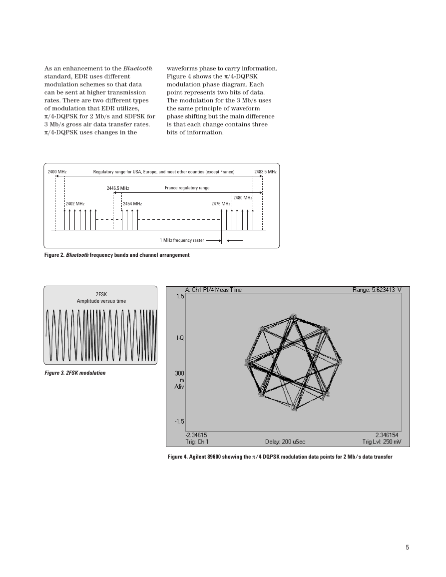
Figure 4 shows the π/4-DQPSK
modulation phase diagram. Each
point represents two bits of data.
The modulation for the 3 Mb/s uses
the same principle of waveform
phase shifting but the main difference
is that each change contains three
bits of information.
2400 MHz
Regulatory range for USA, Europe, and most other counties (except France)
2483.5 MHz
2446.5 MHz
France regulatory range
2402 MHz
2454 MHz
2480 MHz
2476 MHz
Figure 2. Bluetooth frequency bands and channel arrangement
1 MHz frequency raster
2FSK
Amplitude versus time
Figure 3. 2FSK modulation
Figure 4. Agilent 89600 showing the π/4 DQPSK modulation data points for 2 Mb/s data transfer
5
�
1.2 Bluetooth link control unit
and link management
The Bluetooth link control unit,
also known as the link controller,
determines the state of the device
and is responsible for establishing
the network connections as well as
power efficiency, error correction,
and encryption.
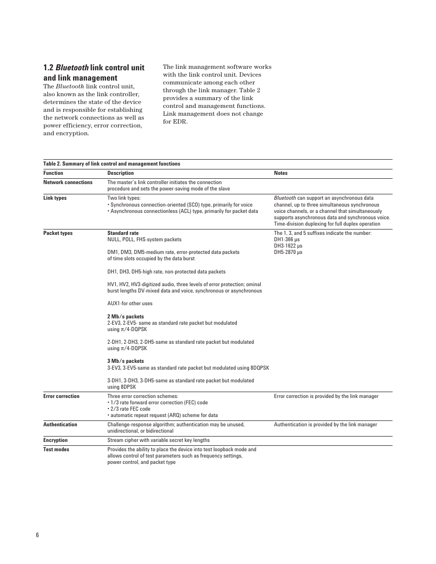
The link management software works
with the link control unit. Devices
communicate among each other
through the link manager. Table 2
provides a summary of the link
control and management functions.
Link management does not change
for EDR.
Table 2. Summary of link control and management functions
Function
Network connections
Description
The master’s link controller initiates the connection
procedure and sets the power-saving mode of the slave
Two link types:
• Synchronous connection-oriented (SCO) type, primarily for voice
• Asynchronous connectionless (ACL) type, primarily for packet data
Link types
Packet types
Standard rate
NULL, POLL, FHS-system packets
DM1, DM3, DM5-medium rate, error-protected data packets
of time slots occupied by the data burst
DH1, DH3, DH5-high rate, non-protected data packets
HV1, HV2, HV3-digitized audio, three levels of error protection; ominal
burst lengths DV-mixed data and voice, synchronous or asynchronous
AUX1-for other uses
2 Mb/s packets
2-EV3, 2-EV5- same as standard rate packet but modulated
using π/4-DQPSK
2-DH1, 2-DH3, 2-DH5-same as standard rate packet but modulated
using π/4-DQPSK
3 Mb/s packets
3-EV3, 3-EV5-same as standard rate packet but modulated using 8DQPSK
3-DH1, 3-DH3, 3-DH5-same as standard rate packet but modulated
using 8DPSK
Three error correction schemes:
• 1/3 rate forward error correction (FEC) code
• 2/3 rate FEC code
• automatic repeat request (ARQ) scheme for data
Challenge-response algorithm; authentication may be unused,
unidirectional, or bidirectional
Stream cipher with variable secret key lengths
Provides the ability to place the device into test loopback mode and
allows control of test parameters such as frequency settings,
power control, and packet type
Error correction
Authentication
Encryption
Test modes
6
Notes
Bluetooth can support an asynchronous data
channel, up to three simultaneous synchronous
voice channels, or a channel that simultaneously
supports asynchronous data and synchronous voice.
Time-division duplexing for full duplex operation
The 1, 3, and 5 suffixes indicate the number:
DH1-366 µs
DH3-1622 µs
DH5-2870 µs
Error correction is provided by the link manager
Authentication is provided by the link manager
�
Bluetooth radios may operate as
either master or slave units. The
link manager sets up the connection
between master and slave units
and also determines the slave’s
power-saving mode. A master can
be actively communicating with
up to seven slaves, while another
200+ slaves can be registered in a
non-communicating, power-saving
mode. This area of control is defined
as a piconet. A master in one piconet
may be a slave to a master from a
different piconet. Similarly, multiple
masters from different piconets may
control a single slave. This network of
piconets is referred to as a scatternet.
Figure 5 depicts two piconets
comprising a scatternet. Units that
are not part of either piconet remain
in standby mode.
The Bluetooth transmission is divided
into time slots, where each slot
corresponds to an RF hop frequency.
In the time division duplex (TDD)
scheme used, the master transmits
in even-numbered time slots, and the
slave in odd numbered time slots.
Voice bits or data bits within piconets
are transmitted in packets. Packets
transmitted by the master or the
slave may extend over one, three, or
five time slots. A packet for standard
Bluetooth transmission, shown in
Figure 6, contains an access code,
a header, and a payload. The access
code consists of a preamble, a sync
word, and an optional trailer. The
header contains piconet address
and packet information. The payload
carries the user’s voice or data
information. Refer to Specification
of the Bluetooth System, Part B:
Baseband Specification, [Reference
2] for further details on packet
construction.
S
S
ps
M
sb
sb
S
S
M
S
ps
S
Figure 5. Network topology
M – Master unit
S – Slave unit
ps – Slave unit in
power-saving mode
sb – Unit in standby mode
72 bits
54 bits
Access code
Header
LSB
0 – 2754 bits
Payload (w/CRC)
MSB
4 bits
Preamble
LSB
64 bits
Sync word (including 3D address)
3 bits
4 bits
1 bit
1 bit
AM_ADDR
Type
Flow
ARQN
LSB
4 bits
Trailer
1 bit
SEQN
8 bits
HEC
MSB
Figure 6. Standard Bluetooth general packet format showing contents of the access code and header
7
�
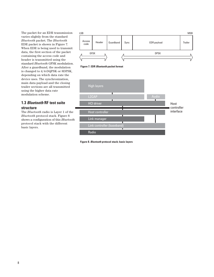
The packet for an EDR transmission
varies slightly from the standard
Bluetooth packet. The Bluetooth
EDR packet is shown in Figure 7.
When EDR is being used to transmit
data, the first section of the packet
containing the access code and
header is transmitted using the
standard Bluetooth GFSK modulation.
After a guardband, the modulation
is changed to π/4-DQPSK or 8DPSK,
depending on which data rate the
device uses. The synchronization,
main data payload and the closing
trailer sections are all transmitted
using the higher data rate
modulation scheme.
1.3 Bluetooth RF test suite
structure
The Bluetooth radio is Layer 1 of the
Bluetooth protocol stack. Figure 8
shows a configuration of this Bluetooth
protocol stack with the different
basic layers.
LSB
Access
code
Header
Guardband
Sync
EDR payload
Trailer
MSB
GFSK
DPSK
Figure 7. EDR Bluetooth packet format
High layers
L2CAP
HCI driver
Host controller
Link manager
Link controller (baseband)
Radio
Figure 8. Bluetooth protocol stack; basic layers
Audio
Host
controller
interface
8
�




 2023年江西萍乡中考道德与法治真题及答案.doc
 2012年重庆南川中考生物真题及答案.doc
 2013年江西师范大学地理学综合及文艺理论基础考研真题.doc
 2020年四川甘孜小升初语文真题及答案I卷.doc
 2020年注册岩土工程师专业基础考试真题及答案.doc
 2023-2024学年福建省厦门市九年级上学期数学月考试题及答案.doc
 2021-2022学年辽宁省沈阳市大东区九年级上学期语文期末试题及答案.doc
 2022-2023学年北京东城区初三第一学期物理期末试卷及答案.doc
 2018上半年江西教师资格初中地理学科知识与教学能力真题及答案.doc
 2012年河北国家公务员申论考试真题及答案-省级.doc
 2020-2021学年江苏省扬州市江都区邵樊片九年级上学期数学第一次质量检测试题及答案.doc
 2022下半年黑龙江教师资格证中学综合素质真题及答案.doc