ICN6211 Specification V0.4
ICN6211 Specification
MIPI® DSI BRIDGE TO RGB output
Revision 0.4
NOTICE NOTICENOTICENOTICENOTICE
This design and all of its related documentation constitutes valuable and confidential
property of Chipone Technology (Beijing) Co., Ltd. It is licensed for use as expressly
stated in the written license Agreement between Chipone Technology (Beijing) Co.,
Ltd and its customers. Any other use or redistribution of this design and all related
documentation is expressly prohibited.
This design and all related documentation have been released by Chipone Technology
(Beijing) Co., Ltd to its customers under a Non Disclosure Agreement (NDA).
Disclosure of this design outside of this agreement is expressly prohibited.
NOTICE NOTICENOTICENOTICENOTICE
香港众鑫微电子有限公司
金生 15013505758 q10862894
深圳市宝安区广源路宝安互联网产业基地A区A栋209D
- 1 -
�
ICN6211 Specification V0.4
Revision History
Rev Date
Author
Description
0.1 2014-03-25 Simon_Liu
0.2 2014-04-23 Simon_Liu
0.3 2014-06-19 Simon_Liu
0.4 2014-07-04 Simon_Liu
Initial version
1. Update pin diagram and pin description
2. Add FRC/Hi-FRC function
3. Add RGB out clock phase control description
Update package diagram
VDD2 & VDD3 should be in same domain.
香港众鑫微电子有限公司
金生 15013505758 q10862894
深圳市宝安区广源路宝安互联网产业基地A区A栋209D
- 2 -
�
ICN6211 Specification V0.4
Table of Contents
1
1.1
2
3
4
5
6
6.1
6.1.1
6.1.2
6.1.3
6.2
6.3
6.4
6.5
6.6
6.6.1
6.6.2
6.7
7
7.1
7.2
7.3
7.3.1
7.3.2
7.4
Introduction ................................................................................................................ - 5 -
Feature List ............................................................................................................................................ - 5 -
Functional Block Diagram ........................................................................................ - 6 -
System Application Diagram .................................................................................... - 7 -
Pin Diagram ................................................................................................................ - 8 -
Pin Description ........................................................................................................... - 9 -
Function Description ................................................................................................ - 11 -
MIPI Receiver ...................................................................................................................................... - 11 -
DSI Lane Merging ................................................................................................................................. - 11 -
DSI Pixel Stream Packets ...................................................................................................................... - 11 -
DSI Video Transmission sequence ........................................................................................................ - 13 -
RGB output .......................................................................................................................................... - 15 -
RGB Clock phase adjust ..................................................................................................................... - 16 -
Bist mode .............................................................................................................................................. - 16 -
FRC/Hi-FRC function ......................................................................................................................... - 17 -
DSI access local registers .................................................................................................................... - 17 -
Write local registers .............................................................................................................................. - 17 -
Read local registers ............................................................................................................................... - 17 -
I2C access local registers .................................................................................................................... - 18 -
DC and AC Electrical Characteristics ................................................................... - 19 -
ABSOLUTE MAXIMUM RATING .................................................................................................. - 19 -
RECOMMENDED OPERATING CONDITIONS .......................................................................... - 19 -
Electrical Characteristics.................................................................................................................... - 20 -
MIPI DSI INTERFACE ........................................................................................................................ - 20 -
RGB output ........................................................................................................................................... - 21 -
SWITCHING CHARACTERISTICS ............................................................................................... - 21 -
8
Package information ................................................................................................ - 23 -
Important Notice .................................................................................................................... - 24 -
香港众鑫微电子有限公司
金生 15013505758 q10862894
深圳市宝安区广源路宝安互联网产业基地A区A栋209D
- 3 -
�
ICN6211 Specification V0.4
Table of figures
Figure 2-1 ICN6211 function block diagram ..................................................................................................... - 6 -
Figure 3-1 ICN6211 system application diagram ............................................................................................... - 7 -
Figure 4-1 ICN6211 QFN48 pin diagram (Top View) ....................................................................................... - 8 -
Figure 6-1 DSI multi-lanes HS Transmission Example ................................................................................... - 11 -
Figure 6-2 DSI RGB666 Color format, Loosely Long Packet ......................................................................... - 12 -
Figure 6-3 DSI RGB666 Color format, Tightly Long Packet .......................................................................... - 12 -
Figure 6-4 DSI RGB888 Color format, Long Packet ....................................................................................... - 12 -
Figure 6-5 Non-Burst Mode with Sync Pulses ................................................................................................. - 13 -
Figure 6-6 Non-Burst Mode with Sync Events ................................................................................................ - 13 -
Figure 6-7 Burst mode ...................................................................................................................................... - 14 -
Figure 6-8 RGB output clock phase delay ........................................................................................................ - 16 -
Figure 6-9 Bist mode pattern sequence ............................................................................................................ - 16 -
Figure 7-1 DSI HS UI timing definition ........................................................................................................... - 20 -
Figure 7-2 DSI HS/LP signaling and Contention Voltage................................................................................ - 21 -
Figure 7-3 RGB output timing ......................................................................................................................... - 22 -
Figure 7-4 Power on and RESET and ULPS timing ........................................................................................ - 22 -
香港众鑫微电子有限公司
金生 15013505758 q10862894
深圳市宝安区广源路宝安互联网产业基地A区A栋209D
- 4 -
�
ICN6211 Specification V0.4
1 Introduction
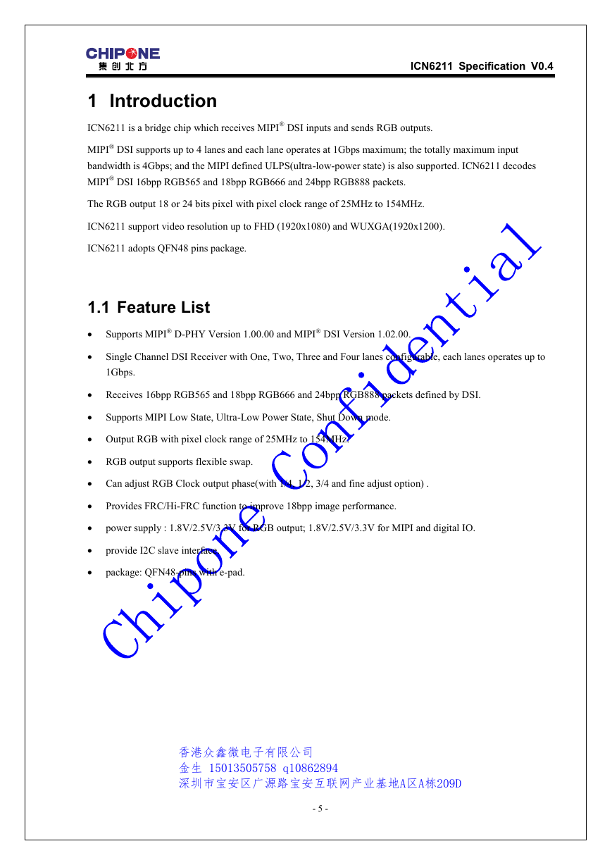
ICN6211 is a bridge chip which receives MIPI® DSI inputs and sends RGB outputs.
MIPI® DSI supports up to 4 lanes and each lane operates at 1Gbps maximum; the totally maximum input
bandwidth is 4Gbps; and the MIPI defined ULPS(ultra-low-power state) is also supported. ICN6211 decodes
MIPI® DSI 16bpp RGB565 and 18bpp RGB666 and 24bpp RGB888 packets.
The RGB output 18 or 24 bits pixel with pixel clock range of 25MHz to 154MHz.
ICN6211 support video resolution up to FHD (1920x1080) and WUXGA(1920x1200).
ICN6211 adopts QFN48 pins package.
1.1 Feature List
Supports MIPI® D-PHY Version 1.00.00 and MIPI® DSI Version 1.02.00.
Single Channel DSI Receiver with One, Two, Three and Four lanes configurable, each lanes operates up to
1Gbps.
Receives 16bpp RGB565 and 18bpp RGB666 and 24bpp RGB888 packets defined by DSI.
Supports MIPI Low State, Ultra-Low Power State, Shut Down mode.
Output RGB with pixel clock range of 25MHz to 154MHz.
RGB output supports flexible swap.
Can adjust RGB Clock output phase(with 1/4, 1/2, 3/4 and fine adjust option) .
Provides FRC/Hi-FRC function to improve 18bpp image performance.
power supply : 1.8V/2.5V/3.3V for RGB output; 1.8V/2.5V/3.3V for MIPI and digital IO.
provide I2C slave interface.
package: QFN48-pins with e-pad.
香港众鑫微电子有限公司
金生 15013505758 q10862894
深圳市宝安区广源路宝安互联网产业基地A区A栋209D
- 5 -
�
ICN6211 Specification V0.4
2 Functional Block Diagram
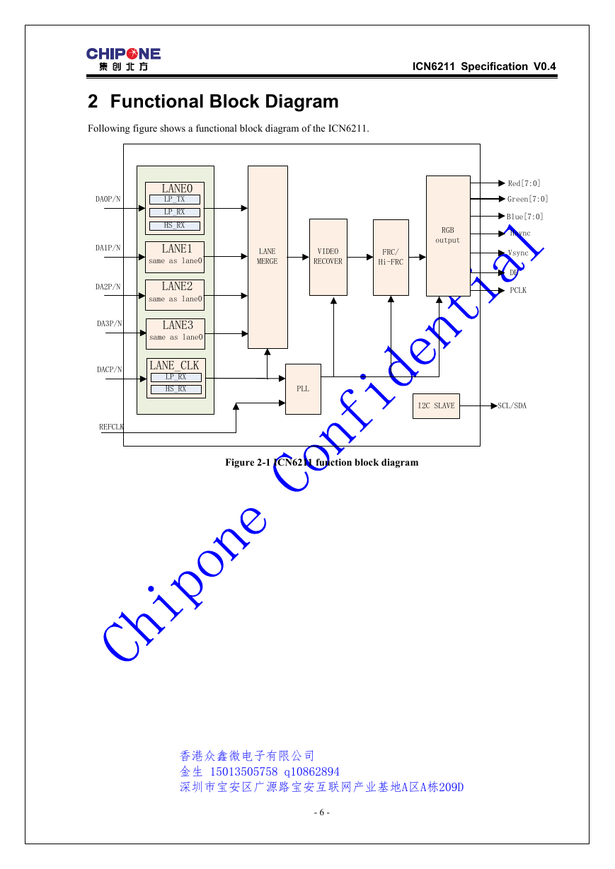
Following figure shows a functional block diagram of the ICN6211.
LANE0
LP_TX
LP_RX
HS_RX
LANE1
same as lane0
LANE2
same as lane0
LANE3
same as lane0
LANE_CLK
LP_RX
HS_RX
DA0P/N
DA1P/N
DA2P/N
DA3P/N
DACP/N
REFCLK
LANE
MERGE
VIDEO
RECOVER
FRC/
Hi-FRC
RGB
output
Red[7:0]
Green[7:0]
Blue[7:0]
Hsync
Vsync
DE
PCLK
PLL
I2C SLAVE
SCL/SDA
Figure 2-1 ICN6211 function block diagram
香港众鑫微电子有限公司
金生 15013505758 q10862894
深圳市宝安区广源路宝安互联网产业基地A区A栋209D
- 6 -
�
ICN6211 Specification V0.4
3 System Application Diagram
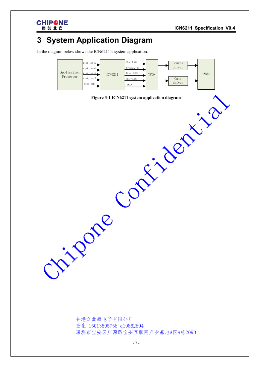
In the diagram below shows the ICN6211’s system application.
Application
Processor
mipi_lane0
mipi_lane1
mipi_lane2
mipi_lane3
mipi_clk
ICN6211
Red[7:0]
Green[7:0]
Blue[7:0]
HS/VS/DE
PCLK
TCON
Source
driver
Gate
driver
PANEL
Figure 3-1 ICN6211 system application diagram
香港众鑫微电子有限公司
金生 15013505758 q10862894
深圳市宝安区广源路宝安互联网产业基地A区A栋209D
- 7 -
�
4 Pin Diagram
ICN6211 Specification V0.4
D
A
T
A
6
G
N
D
D
A
T
A
5
D
A
T
A
4
D
A
T
A
3
D
A
T
A
2
D
A
T
A
1
D
A
T
A
0
D
A
T
A
_
D
E
V
S
Y
N
C
H
S
Y
N
C
P
C
L
K
36 35 34 33 32 31 30 29 28 27 26
25
CHIPONE
ICN6211 QFN48
24
23
22
21
20
19
18
17
16
15
14
13
VDD2
DA3N
DA3P
DA2N
DA2P
DACN
DACP
DA1N
DA1P
DA0N
DA0P
REF_CLK
DATA7
DATA8
DATA9
VCORE
DATA10
DATA11
DATA12
DATA13
DATA14
DATA15
DATA16
DATA17
37
38
39
40
41
42
43
44
45
46
47
48
1 2 3 4 5 6 7 8 9 10 11
12
D
A
T
A
1
8
D
A
T
A
1
9
V
D
D
3
D
A
T
A
2
0
D
A
T
A
2
1
D
A
T
A
2
2
D
A
T
A
2
3
T
E
S
T
S
C
L
S
D
A
E
N
V
D
D
1
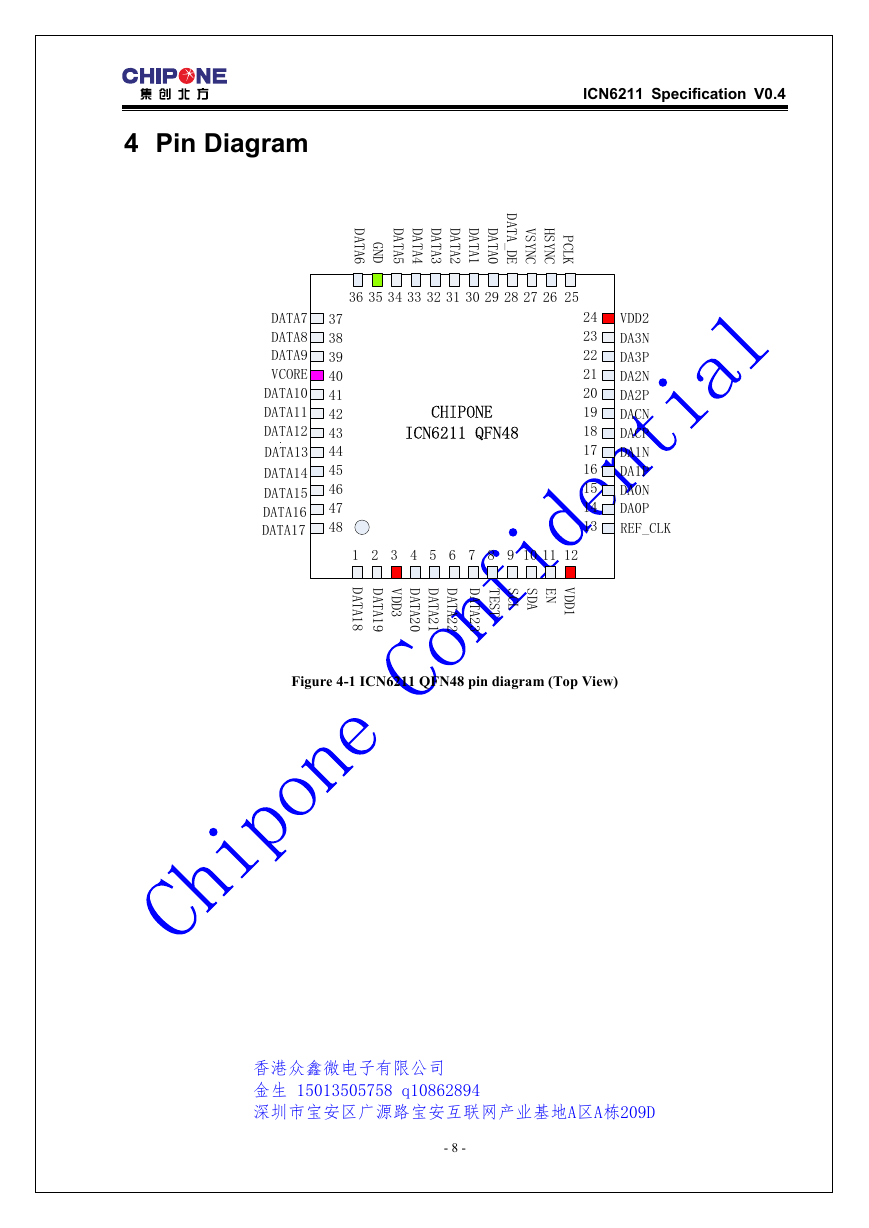
Figure 4-1 ICN6211 QFN48 pin diagram (Top View)
香港众鑫微电子有限公司
金生 15013505758 q10862894
深圳市宝安区广源路宝安互联网产业基地A区A栋209D
- 8 -
�


 2023年江西萍乡中考道德与法治真题及答案.doc
 2012年重庆南川中考生物真题及答案.doc
 2013年江西师范大学地理学综合及文艺理论基础考研真题.doc
 2020年四川甘孜小升初语文真题及答案I卷.doc
 2020年注册岩土工程师专业基础考试真题及答案.doc
 2023-2024学年福建省厦门市九年级上学期数学月考试题及答案.doc
 2021-2022学年辽宁省沈阳市大东区九年级上学期语文期末试题及答案.doc
 2022-2023学年北京东城区初三第一学期物理期末试卷及答案.doc
 2018上半年江西教师资格初中地理学科知识与教学能力真题及答案.doc
 2012年河北国家公务员申论考试真题及答案-省级.doc
 2020-2021学年江苏省扬州市江都区邵樊片九年级上学期数学第一次质量检测试题及答案.doc
 2022下半年黑龙江教师资格证中学综合素质真题及答案.doc