logo资料库

BCM54616S datasheet.pdf

第1页 / 共188页
第2页 / 共188页
第3页 / 共188页
第4页 / 共188页
第5页 / 共188页
第6页 / 共188页
第7页 / 共188页
第8页 / 共188页
资料共188页,剩余部分请下载后查看
BCM54616S Data Sheet
Revision History
Table of Contents
List of Figures
List of Tables
Section 1: Functional Description
Overview
Modes of Operation
Reduced Gigabit Media Independent Interface
Serial GMII Interface
SerDes Interface (Complies with IEEE 802.3™, Clauses 36 and 37)
Management Interface
Encoder
Decoder
Carrier Sense
Link Monitor
Digital Adaptive Equalizer
Echo Canceler
Crosstalk Canceler
Analog-to-Digital Converter
Clock Recovery/Generator
Baseline Wander Correction
Multimode TX Digital-to-Analog Converter
Stream Cipher
Wire Map and Pair Skew Correction
Automatic MDI Crossover
10/100BASE-T Forced Mode Auto-MDIX
Auto-Negotiation
Copper Mode
SGMII Mode
Ethernet@Wirespeed
Software Disable
Changing the Number of Failed Link Attempts Before Ethernet@Wirespeed Downgrade
Monitoring Ethernet@Wirespeed
Synchronous Ethernet
Energy Detect
Internal Voltage Regulator
Power-Down Modes
Jumbo Packets
Broadcom Serial Control Interface
BSC Master Mode
BSC Slave Mode
Section 2: Hardware Signal Descriptions
Section 3: Pinout
Section 4: Operational Description
Reset
PHY Address
Isolate Mode
Standby Power-Down Mode
Auto Power-Down Mode
CLK125 Clock Output
Ultra-Low Power-Down Mode
Reset Requirements
Internal Loopback Mode
Lineside (Remote) Loopback Mode
External Loopback Mode
Full-Duplex Operation
Master/Slave Configuration
Next Page Exchange
RGMII Interface
SGMII Interface
Control Information Exchange Between Links
Internal Voltage Regulator
Dual-Input Configuration/LED Output Function
General Purpose LED Programmability
Interrupt Function
LED Modes
Multicolor LED
Energy Link LED
Additional LED Modes
Section 5: Register Summary
MII Management Interface Register Programming
Preamble (PRE)
Start of Frame (ST)
Operation Code (OP)
PHY Address (PHYAD)
Register Address (REGAD)
Turnaround (TA)
Data
Register Map
Register Notations
1000BASE-T/100BASE-TX/10BASE-T Register Descriptions
Register 00h: 1000BASE-T/100BASE-TX/10BASE-T MII Control
Reset
Internal Loopback
Speed Selection (LSB)
Auto-Negotiation Enable
Power-Down
Isolate
Restart Auto-Negotiation
Duplex Mode
Speed Selection (MSB)
Collision Test
Register 01h: 1000BASE-T/100BASE-TX/10BASE-T MII Status
100BASE-T4 Capable
100BASE-TX Full-Duplex Capable
100BASE-TX Half-Duplex Capable
10BASE-T Full-Duplex Capable
10BASE-T Half-Duplex Capable
100BASE-T2 Full-Duplex Capable
100BASE-T2 Half-Duplex Capable
Extended Status
Management Frames Preamble Suppression
Auto-Negotiation Complete
Remote Fault
Auto-Negotiation Ability
Link Status
Jabber Detect
Extended Capability
Register 02h and 03h: 1000BASE-T/100BASE-TX/10BASE-T PHY Identifier
Register 04h: 1000BASE-T/100BASE-TX/10BASE-T Auto-Negotiation Advertisement
Next Page
Remote Fault
Reserved Technology
Asymmetric Pause
Pause Capable
100BASE-T4 Capable
100BASE-TX Full-Duplex Capable
100BASE-TX Half-Duplex Capable
10BASE-T Full-Duplex Capable
10BASE-T Half-Duplex Capable
Selector Field
Register 05h: 1000BASE-T/100BASE-TX/10BASE-T Auto-Negotiation Link Partner Ability
Next Page
Acknowledge
Remote Fault
Reserved Technology
Asymmetric Pause
Pause Capable
100BASE-T4 Capable
100BASE-TX Full-Duplex Capable
100BASE-TX Half-Duplex Capable
10BASE-T Full-Duplex Capable
10BASE-T Half-Duplex Capable
Protocol Selector Field
Register 06h: 1000BASE-T/100BASE-TX/10BASE-T Auto-Negotiation Expansion
NEXT_PAGE_RECEIVE_LOCATION_ABLE
NEXT_PAGE_RECEIVE_LOCATION
Parallel Detection Fault
Link Partner Next Page Ability
Next Page Capable
Page Received
Link Partner Auto-Negotiation Ability
Register 07h: 1000BASE-T/100BASE-TX/10BASE-T Next Page Transmit
Next Page
Message Page
Acknowledge2
Toggle
Message/Unformatted Code Field
Register 08h: 1000BASE-T/100BASE-TX/10BASE-T Link Partner Received Next Page
Next Page
Acknowledge
Message Page
Acknowledge2
Toggle
Message Code Field
Register 09h: 1000BASE-T Control
Test Mode
Master/Slave Configuration Enable
Master/Slave Configuration Value
Repeater/DTE
Advertise 1000BASE-T Full-Duplex Capability
Advertise 1000BASE-T Half-Duplex Capability
Register 0Ah: 1000BASE-T Status
Master/Slave Configuration Fault
Master/Slave Configuration Resolution
Local Receiver Status
Remote Receiver Status
1000BASE-T Full-Duplex Capability
1000BASE-T Half-Duplex Capability
Idle Error Count
Register 0Fh: 1000BASE-T/100BASE-TX/10BASE-T IEEE Extended Status
1000BASE-X Full-Duplex Capable
1000BASE-X Half-Duplex Capable
1000BASE-T Full-Duplex Capable
1000BASE-T Half-Duplex Capable
Auxiliary Register DescriptionsRegister 10h: 1000BASE-T/ 100BASE-TX/10BASE-T PHY Extended Control
MAC/PHY Interface Mode
Disable Automatic MDI Crossover
Transmit Disable
Interrupt Disable
Force Interrupt
Bypass 4B/5B Encoder/Decoder (100BASE-TX)
Bypass Scrambler/Descrambler (100BASE-TX)
Bypass MLT3 Encoder/Decoder (100BASE-TX)
Bypass Receive Symbol Alignment (100BASE-TX)
Reset Scrambler (100BASE-TX)
Enable LED Traffic Mode
Force LEDs On
Force LEDs Off
1000BASE-T PCS Transmit FIFO Elasticity (Copper Mode)
Register 11h: 1000BASE-T/100BASE-TX/10BASE-T PHY Extended Status
Auto-Negotiation Base Page Selector Field Mismatch
MDI Crossover State
Interrupt Status
Remote Receiver Status
Local Receiver Status
Locked
Link Status
CRC Error Detected
Carrier Extension Error Detected
Bad SSD Detected (False Carrier)
Bad ESD Detected (Premature End)
Receive Error Detected
Transmit Error Detected
Lock Error Detected
MLT3 Code Error Detected
Register 12h: 1000BASE-T/100BASE-TX/10BASE-T Receive Error Counter
Receive Error Counter
Register 13h: 1000BASE-T/100BASE-TX/10BASE-T False Carrier Sense Counter
False Carrier Sense Counter
Register 14h: 1000BASE-T/100BASE-TX/10BASE-T Receiver NOT_OK Counter
Local Receiver NOT_OK Counter
Remote Receiver NOT_OK Counter
Register 17h: Expansion Register Access
Expansion Register Select
Expansion Register Address
Register 18h: Shadow Access
Register 18h (Shadow 000): Auxiliary Control Register
External Loopback
Extended Packet Length
Edge Rate Control (1000BASE-T)
Transmit Mode
Disable Partial Response Filter
Edge Rate Control (100BASE-TX)
Shadow Register Select
Register 18h (Shadow 001): 10BASE-T
Manchester Code Error
EOF Error
Polarity Error
Block RX_DV Extension (IPG)
10BASE-T TXC Invert Mode
Jabber Disable
1000BASE-T Signal Detect Threshold
10BASE-T Signal Detect Threshold
10BASE-T Echo Mode
SQE Enable Mode
10BASE-T No Dribble
Shadow Register Select
Register 18h (Shadow 010): Power/MII Control
Super Isolate
Shadow Register Select
Register 18h (Shadow 100): Miscellaneous Test Register
Lineside [Remote] Loopback Enable
Lineside [Remote] Loopback Tristate
Swap RX MDIX
10BASE-T Half-Out
Shadow Register Select
Register 18h (Shadow 111): Miscellaneous Control
Write Enable (Bits 11:3)
Shadow Register Read Selector
Packet Counter Mode
Bypass Wirespeed Timer
Force Auto-MDIX Mode
RGMII RXD to RXC Skew
RGMII Enable
RGMII out-of-band status disable
Ethernet @Wirespeed Enable
Shadow Register Select
Register 19h: Auxiliary Status Summary
Auto-Negotiation Complete
Auto-Negotiation Complete Acknowledge
Auto-Negotiation Acknowledge Detect
Auto-Negotiation Ability Detect
Auto-Negotiation Next Page Wait
Auto-Negotiation HCD (Current Operating Speed and Duplex Mode)
Parallel Detection Fault
Remote Fault
Auto-Negotiation Page Received
Link Partner Auto-Negotiation Ability
Link Partner Next Page Ability
Link Status
Pause Resolution—Receive Direction and Transmit Direction
Register 1Ah: Interrupt Status
Energy Detect Change
Illegal Pair Swap
MDIX Status Change
Exceeded High Counter Threshold
Exceeded Low Counter Threshold
Auto-Negotiation Page Received
No HCD Link
No HCD
Negotiated Unsupported HCD
Scrambler Synchronization Error
Remote Receiver Status Change
Local Receiver Status Change
Duplex Mode Change
Link Speed Change
Link Status Change
CRC Error
Register 1Bh: Interrupt Mask
Interrupt Mask Vector
Register 1Ch Access
Register 1Ch (Shadow 00010): Spare Control 1
Write Enable
Shadow Register Selector
100BASE-FX Mode Copper Path
Link LED Mode
Register 1Ch (Shadow 00011): Clock Alignment Control
Write Enable
Shadow Register Selector
GTXCLK Clock Delay Enable
Register 1Ch (Shadow 00100): Spare Control 2
Write Enable
Shadow Register Selector
Energy Detect on INTR Pin
Register 1Ch (Shadow 00101): Spare Control 3
Write Enable
Shadow Register Selector
TXC/RXC Disable During Auto Power-Down
CLK125 Auto Power-Down
CLK125 Output
Register 1Ch (Shadow 01000): LED Status
Write Enable
Shadow Register Selector
Slave Indicator
FDX Indicator
INTR Indicator
LINKSPD Indicator
Transmit Indicator
Receive Indicator
Quality Indicator
Register 1Ch (Shadow 01001): LED Control
Write Enable
Shadow Register Selector
Activity/Link LED Enable
ACTIVITY LED Enable
Remote Fault LED Enable
Link Utilization LED Selector
Register 1Ch (Shadow 01010): Auto Power-Down
Write Enable
Shadow Register Selector
Auto Power-Down Mode
Sleep Timer Select
Wake-up Timer Select
Register 1Ch (Shadow 01100): External Control 2 Register
Write Enable
Shadow Register Selector
Enable IDDQ
Register 1Ch (Shadow 01101): LED Selector 1
Write Enable
Shadow Register Selector
LED2 Selector
LED1 Selector
Register 1Ch (Shadow 01110): LED Selector 2
Write Enable
Shadow Register Selector
LED4 Selector
LED3 Selector
Register 1Ch (Shadow 01111): LED GPIO Control/Status
Write Enable
Shadow Register Selector
LED I/O Status
Programmable LED I/O Control
Register 1Ch (Shadow 10001): SerDes 100-FX Status Register
Write Enable
Shadow Register Selector
100FX Link Status Change
Bad ESD Detected
False Carrier Detected
Transmit Error Detected
Receive Error Detected
Lock Timer Expired
Lost Lock
Faulting
Locked
100FX Link
Register 1Ch (Shadow 10011): SerDes 100-FX Control Register
Write Enable
Shadow Register Selector
100-FX Auto-Detect Timer Select
Disable RX Qualify
Force RX Qualify
Far End Fault Enable
Auto-Detect 100-FX SerDes
100-FX SerDes Full-Duplex
100-FX SerDes Enable
Register 1Ch (Shadow 10101): SGMII Slave Register
Write Enable
Shadow Register Selector
SerDes Link
SerDes Duplex
SerDes Speed
SerDes Link Status Change
Interface Select
RGMII SGMII Freq Lock Mode
SGMII Slave Mode
SGMII Slave Auto-Detection
Register 1Ch (Shadow 11000): 1000BASE-X Auto-Detect SGMII
Write Enable
Shadow Register Selector
SerDes Resolution Fault
1000BASE-T PCS Transmit FIFO Elasticity
SGMII 10/100BASE-T RX FIFO Frequency Lock Mode
Register 1Ch (Shadow 11110): Auto-Detect Medium Register
Write Enable
Shadow Register Selector
Invert Fiber SD From Pin
Fiber In Use LED Mode
Fiber LED Mode
Fiber Auto-Power Down Mode
Auto-Detect Medium Default
Auto-Detect Medium Priority
Auto-Detect Medium Enable
Register 1Ch (Shadow 11111): Mode Control Register
Write Enable
Shadow Register Selector
Interface Mode Select Change
Copper Link
SerDes link
Copper Energy Detect
Fiber Signal Detect
Interface Select
Enable 1000-X Registers
Register 1Dh (Bit 15 = 0): Master/Slave Seed
Enable Shadow Register
Master/Slave Seed Match
Link Partner Repeater/DTE Bit
Link Partner Manual Master/Slave Configuration Value
Link Partner Manual Master/Slave Configuration Enable
Local Master/Slave Seed Value
Register 1Dh (Bit 15 = 1): HCD Status
Enable Shadow Register
HCD 1000BASE-T FDX
HCD 1000BASE-T
HCD 100BASE-TX FDX
HCD 100BASE-TX
HCD 10BASE-T FDX
HCD 10BASE-T
HCD 1000BASE-T FDX (Link Never Came Up)
HCD 1000BASE-T (Link Never Came Up)
HCD 100BASE-TX FDX (Link Never Came Up)
HCD 100BASE-TX (Link Never Came Up)
HCD 10BASE-T FDX (Link Never Came Up)
Register 1Eh: Test Register 1
CRC Error Counter Selector
Force Link
Manual Swap MDI State
SerDes Register Descriptions
1000BASE-X MII Control
Reset
Internal Loopback
Auto-Negotiation Enable
Power-Down
Isolate
Restart Auto-negotiation
Duplex Mode
Collision Test
1000BASE-X MII Status
100BASE-T4 Capable
100BASE-X Full-Duplex Capable
100BASE-X Half-Duplex Capable
10BASE-T Full-Duplex Capable
10BASE-T Half-Duplex Capable
100BASE-T2 Full-Duplex Capable
100BASE-T2 Half-Duplex Capable
Extended Status
Management Frames Preamble Suppression
Auto-Negotiation Complete
Remote Fault
Auto-negotiation Ability
Link Status
Jabber Detect
Extended Capability
1000BASE-X Auto-Negotiation Advertisement
Remote Fault
Pause
Half-Duplex Capable
Full-Duplex Capable
1000BASE-X Auto-Negotiation Link Partner Ability
1000BASE-X Mode
Next Page
Acknowledge
Remote Fault
Pause
Half-Duplex Capable
Full-Duplex Capable
SGMII Mode
Copper Link
Acknowledge
Copper Duplex
Copper Speed
1000BASE-X Auto-Negotiation Extended Status
Next Page Capable
Page Received
1000BASE-X IEEE Extended Status
1000BASE-X Full-Duplex Capable
1000BASE-X Half-Duplex Capable
1000BASE-T Full-Duplex Capable
1000BASE-T Half-Duplex Capable
Expansion Registers
Expansion Register 00h: Receive/Transmit Packet Counter
Packet Counter
Expansion Register 04h: Multicolor LED Selector
Flash Now
In Phase
MULTICOLOR[2] LED Selector
MULTICOLOR[1] LED Selector
Expansion Register 05h: Multicolor LED Flash Rate Controls
Alternating Rate
Flash Rate
Expansion Register 06h: Multicolor LED Programmable Blink Controls
Blink Update Now
Blink Rate
Expansion Register 08h: 10BT Controls
Auto Early DAC Wake
Expansion Register 0Eh: Synchronous Ethernet Controls
MII-Lite Enable
TX SOP Enable
TX SOP Select
RX SOP Enable
RX SOP Select
RXCLK Select
RX_ER Mux Control
Expansion Register 44h: Recovered Clock Controls
Recovered Clock Enable
Section 6: Timing and AC Characteristics
Section 7: Electrical Characteristics
Section 8: Mechanical and Thermal
RoHS-Compliant Packaging
Mechanical Information
Thermal Information
Section 9: Ordering Information
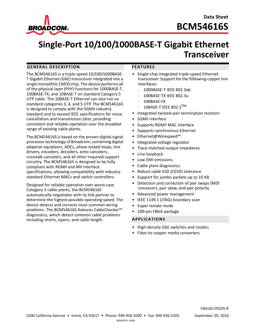
Data Sheet BCM54616S Single-Port 10/100/1000BASE-T Gigabit Ethernet Transceiver GENERAL DESCRIPTION The BCM54616S is a triple-speed 10/100/1000BASE- T Gigabit Ethernet (GbE) transceiver integrated into a single monolithic CMOS chip. The device performs all of the physical layer (PHY) functions for 1000BASE-T, 100BASE-TX, and 10BASE-T on standard Category 5 UTP cable. The 10BASE-T Ethernet can also run on standard categories 3, 4, and 5 UTP. The BCM54616S is designed to comply with the SGMII industry standard and to exceed IEEE specifications for noise cancellation and transmission jitter, providing consistent and reliable operation over the broadest range of existing cable plants. The BCM54616S is based on the proven digital-signal processor technology of Broadcom, combining digital adaptive equalizers, ADCs, phase locked loops, line drivers, encoders, decoders, echo cancelers, crosstalk cancelers, and all other required support circuitry. The BCM54616S is designed to be fully compliant with RGMII and MII interface specifications, allowing compatibility with industry- standard Ethernet MACs and switch controllers. Designed for reliable operation over worst-case Category 5 cable plants, the BCM54616S automatically negotiates with its link partner to determine the highest possible operating speed. The device detects and corrects most common wiring problems. The BCM54616S features CableChecker™ diagnostics, which detect common cable problems including shorts, opens, and cable length. FEATURES • Single-chip integrated triple-speed Ethernet transceiver. Support for the following copper line interfaces: - 1000BASE-T IEEE 802.3ab - 100BASE-TX IEEE 802.3u - 100BASE-FX - 10BASE-T IEEE 802.3TM • Integrated twisted-pair termination resistors • SGMII interface • Supports RGMII MAC interface • Supports synchronous Ethernet • Ethernet@Wirespeed™ • Integrated voltage regulator • Trace matched output impedance • Line loopback • Low EMI emissions • Cable plant diagnostics • Robust cable ESD (CESD) tolerance • Support for jumbo packets up to 10 KB • Detection and correction of pair swaps (MDI crossover), pair skew, and pair polarity • Advanced power management • IEEE 1149.1 (JTAG) boundary scan • Super Isolate mode • 100-pin FBGA package APPLICATIONS • High-density GbE switches and routers • Fiber-to-copper media converters 5300 California Avenue • Irvine, CA 92617 • Phone: 949-926-5000 • Fax: 949-926-5203 9/24/2010 1539I 54616S-DS205-R September 20, 2010
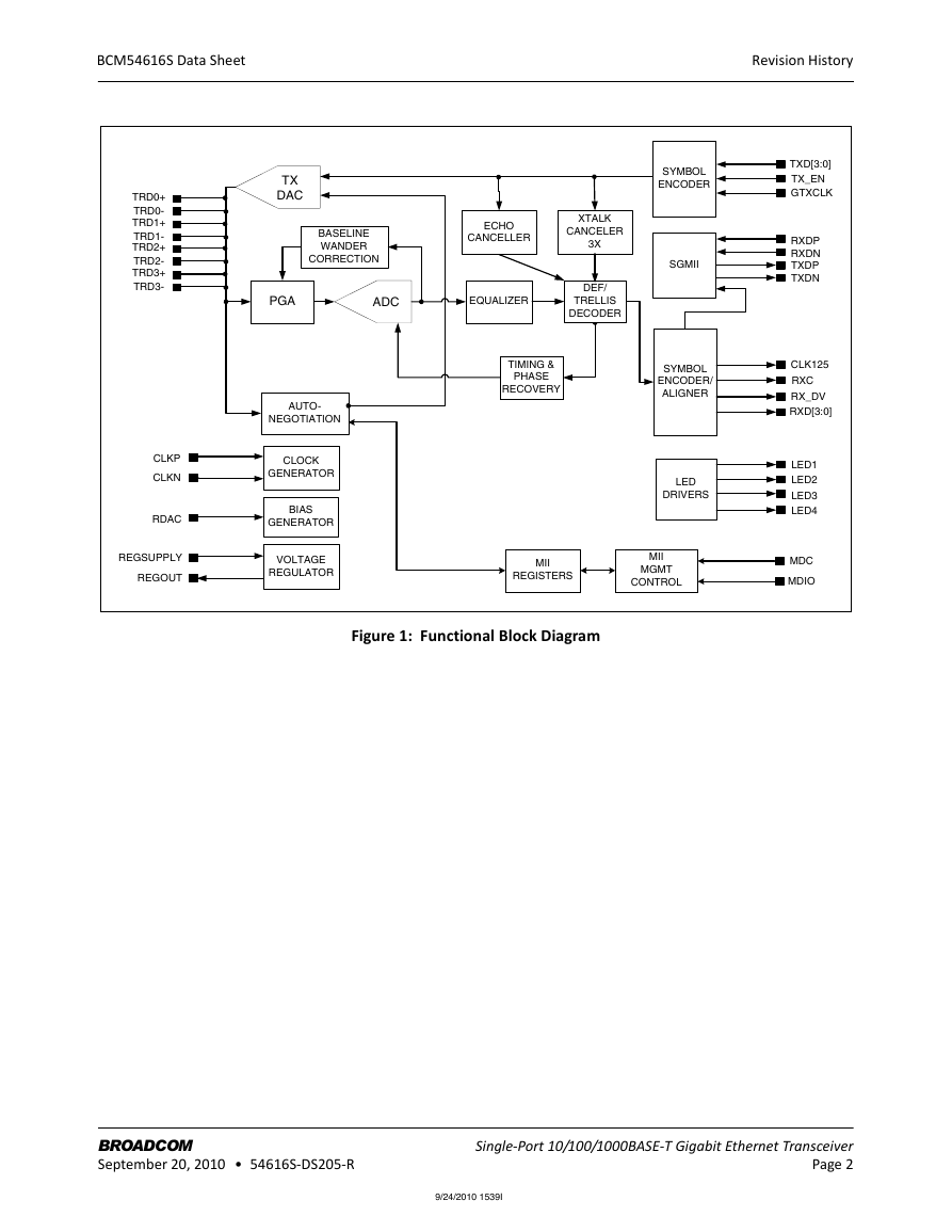
BCM54616S Data Sheet Revision History TRD0+ TRD0- TRD1+ TRD1- TRD2+ TRD2- TRD3+ TRD3- CLKP CLKN RDAC REGSUPPLY REGOUT AUTO- NEGOTIATION CLOCK GENERATOR BIAS GENERATOR VOLTAGE REGULATOR SYMBOL ENCODER SGMII SYMBOL ENCODER/ ALIGNER LED DRIVERS TXD[3:0] TX_EN GTXCLK RXDP RXDN TXDP TXDN CLK125 RXC RX_DV RXD[3:0] LED1 LED2 LED3 LED4 MDC MDIO TX DAC BASELINE WANDER CORRECTION ECHO CANCELLER PGA ADC EQUALIZER XTALK CANCELER 3X DEF/ TRELLIS DECODER TIMING & PHASE RECOVERY MII REGISTERS MII MGMT CONTROL Figure 1: Functional Block Diagram BROADCOM September 20, 2010 • 54616S-DS205-R Single-Port 10/100/1000BASE-T Gigabit Ethernet Transceiver Page 2 9/24/2010 1539I
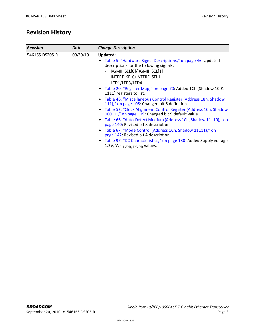
BCM54616S Data Sheet Revision History Revision 54616S-DS205-R Date 09/20/10 Revision History Change Description Updated: • Table 5: “Hardware Signal Descriptions,” on page 46: Updated descriptions for the following signals: - RGMII_SEL[0]/RGMII_SEL[1] - INTERF_SEL0/INTERF_SEL1 LED1/LED3/LED4 - • Table 20: “Register Map,” on page 70: Added 1Ch (Shadow 1001– 1111) registers to list. • Table 46: “Miscellaneous Control Register (Address 18h, Shadow 111),” on page 108: Changed bit 5 definition. • Table 52: “Clock Alignment Control Register (Address 1Ch, Shadow 00011),” on page 119: Changed bit 9 default value. • Table 66: “Auto-Detect Medium (Address 1Ch, Shadow 11110),” on page 140: Revised bit 8 description. • Table 67: “Mode Control (Address 1Ch, Shadow 11111),” on page 142: Revised bit 4 description. • Table 97: “DC Characteristics,” on page 180: Added Supply voltage 1.2V, VSPLLVDD, TXVDD values. BROADCOM September 20, 2010 • 54616S-DS205-R Single-Port 10/100/1000BASE-T Gigabit Ethernet Transceiver Page 3 9/24/2010 1539I
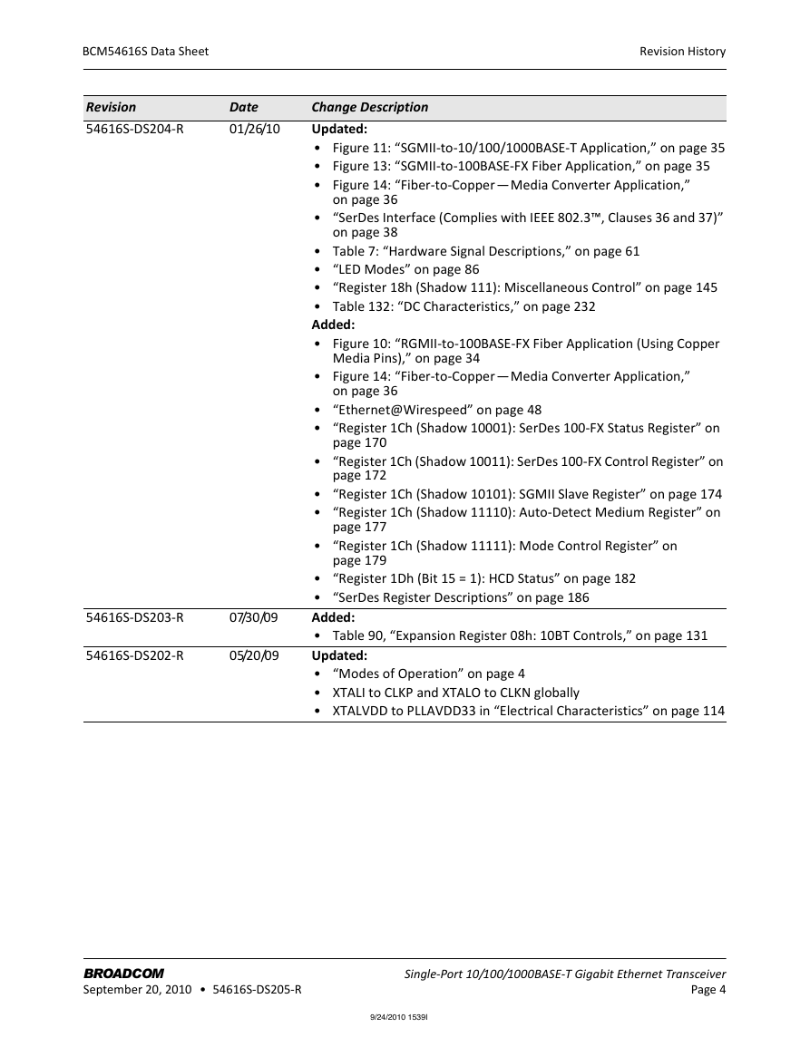
BCM54616S Data Sheet Revision History Revision 54616S-DS204-R Date 01/26/10 54616S-DS203-R 07/30/09 54616S-DS202-R 05/20/09 Change Description Updated: • Figure 11: “SGMII-to-10/100/1000BASE-T Application,” on page 35 • Figure 13: “SGMII-to-100BASE-FX Fiber Application,” on page 35 • Figure 14: “Fiber-to-Copper — Media Converter Application,” on page 36 • “SerDes Interface (Complies with IEEE 802.3™, Clauses 36 and 37)” on page 38 • Table 7: “Hardware Signal Descriptions,” on page 61 • “LED Modes” on page 86 • “Register 18h (Shadow 111): Miscellaneous Control” on page 145 • Table 132: “DC Characteristics,” on page 232 Added: • Figure 10: “RGMII-to-100BASE-FX Fiber Application (Using Copper Media Pins),” on page 34 • Figure 14: “Fiber-to-Copper — Media Converter Application,” on page 36 • “Ethernet@Wirespeed” on page 48 • “Register 1Ch (Shadow 10001): SerDes 100-FX Status Register” on page 170 • “Register 1Ch (Shadow 10011): SerDes 100-FX Control Register” on page 172 • “Register 1Ch (Shadow 10101): SGMII Slave Register” on page 174 • “Register 1Ch (Shadow 11110): Auto-Detect Medium Register” on page 177 • “Register 1Ch (Shadow 11111): Mode Control Register” on page 179 • “Register 1Dh (Bit 15 = 1): HCD Status” on page 182 • “SerDes Register Descriptions” on page 186 Added: • Table 90, “Expansion Register 08h: 10BT Controls,” on page 131 Updated: • “Modes of Operation” on page 4 • XTALI to CLKP and XTALO to CLKN globally • XTALVDD to PLLAVDD33 in “Electrical Characteristics” on page 114 BROADCOM September 20, 2010 • 54616S-DS205-R Single-Port 10/100/1000BASE-T Gigabit Ethernet Transceiver Page 4 9/24/2010 1539I
BCM54616S Data Sheet Revision History Revision 54616S-DS201-R Date 04/14/09 Change Description Updated: • Figure 8, “RGMII-to-1000BASE-X Fiber Application,” on page 3 • Table 6, “Hardware Signal Descriptions,” on page 28 • Figure 15, “100-Pin FBGA SerDes Pinout Diagram, Top View,” on page 35 • “100BASE-TX Half-Duplex Capable” on page 65 • “10BASE-T Half-Duplex Capable” on page 65 • “Register 06h: 1000BASE-T/100BASE-TX/10BASE-T Auto- Negotiation Expansion” on page 67 • Bit 8 default in Table 37, “1000BASE-T Control Register (Address 09h),” on page 71 • Bits 15:6 default in Table 65, “1000BASE-T/100BASE-TX/10BASE-T Power/MII Control Register (Address 18h, Shadow 010),” on page 97 • Bits 14:12 default in Table 66, “Miscellaneous Test Register (Address 18h, Shadow 100),” on page 98 • Bits 8:3 default in Table 67, “Miscellaneous Control Register (Address 18h, Shadow 111),” on page 99 • Bits 9:5 and 3:1 defaults in Table 72, “Spare Control 1 Register (Address 1Ch, Shadow 00010),” on page 106 • Default values in Table 76, “LED Status Register (Address 1Ch, Shadow 01000),” on page 111 • Bit 2 default in Table 77, “LED Control Register (Address 1Ch, Shadow 01001),” on page 113 • Table 112, “Main Differences Between Standard and RoHS- Compliant Packages,” on page 150 54616S-DS200-R 10/22/08 • “Ordering Information” on page 154 Initial release BROADCOM September 20, 2010 • 54616S-DS205-R Single-Port 10/100/1000BASE-T Gigabit Ethernet Transceiver Page 5 9/24/2010 1539I
Broadcom Corporation 5300 California Avenue Irvine, CA 92617 © 2010 by Broadcom Corporation All rights reserved Printed in the U.S.A. Broadcom®, the pulse logo, Connecting everything®, the Connecting everything logo, and CableChecker™ are among the trademarks of Broadcom Corporation and/or its affiliates in the United States, certain other countries and/or the EU. Any other trademarks or trade names mentioned are the property of their respective owners. This data sheet (including, without limitation, the Broadcom component(s) identified herein) is not designed, intended, or certified for use in any military, nuclear, medical, mass transportation, aviation, navigations, pollution control, hazardous substances management, or other high-risk application. BROADCOM PROVIDES THIS DATA SHEET “AS-IS,” WITHOUT WARRANTY OF ANY KIND. BROADCOM DISCLAIMS ALL WARRANTIES, EXPRESSED AND IMPLIED, INCLUDING, WITHOUT LIMITATION, THE IMPLIED WARRANTIES OF MERCHANTABILITY, FITNESS FOR A PARTICULAR PURPOSE, AND NON-INFRINGEMENT. 9/24/2010 1539I
BCM54616S Data Sheet Table of Contents Table of Contents Section 1: Functional Description .................................................................................... 27 Overview.......................................................................................................................................................27 Modes of Operation .....................................................................................................................................31 Reduced Gigabit Media Independent Interface ..........................................................................................31 Serial GMII Interface ....................................................................................................................................31 SerDes Interface (Complies with IEEE 802.3™, Clauses 36 and 37) .......................................................32 Management Interface.................................................................................................................................33 Encoder .........................................................................................................................................................33 Decoder.........................................................................................................................................................34 Carrier Sense.................................................................................................................................................34 Link Monitor .................................................................................................................................................35 Digital Adaptive Equalizer ............................................................................................................................35 Echo Canceler ...............................................................................................................................................35 Crosstalk Canceler ........................................................................................................................................36 Analog-to-Digital Converter .........................................................................................................................36 Clock Recovery/Generator...........................................................................................................................36 Baseline Wander Correction ........................................................................................................................36 Multimode TX Digital-to-Analog Converter.................................................................................................37 Stream Cipher ...............................................................................................................................................37 Wire Map and Pair Skew Correction............................................................................................................38 Automatic MDI Crossover ............................................................................................................................38 10/100BASE-T Forced Mode Auto-MDIX .....................................................................................................39 Auto-Negotiation..........................................................................................................................................39 Copper Mode .........................................................................................................................................39 SGMII Mode ...........................................................................................................................................39 Ethernet@Wirespeed...................................................................................................................................40 Software Disable....................................................................................................................................41 Changing the Number of Failed Link Attempts Before Ethernet@Wirespeed Downgrade ...........41 Monitoring Ethernet@Wirespeed..................................................................................................41 Synchronous Ethernet ..................................................................................................................................42 Energy Detect ...............................................................................................................................................42 Internal Voltage Regulator...........................................................................................................................42 Power-Down Modes.....................................................................................................................................43 Jumbo Packets ..............................................................................................................................................43 BROADCOM September 20, 2010 • 54616S-DS205-R ® Single-Port 10/100/1000BASE-T Gigabit Ethernet Transceiver Page 7 9/24/2010 1539I
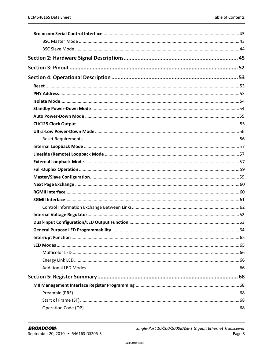
BCM54616S Data Sheet Table of Contents Broadcom Serial Control Interface...............................................................................................................43 BSC Master Mode ..................................................................................................................................43 BSC Slave Mode .....................................................................................................................................44 Section 2: Hardware Signal Descriptions.......................................................................... 45 Section 3: Pinout ............................................................................................................. 52 Section 4: Operational Description .................................................................................. 53 Reset .............................................................................................................................................................53 PHY Address..................................................................................................................................................53 Isolate Mode.................................................................................................................................................54 Standby Power-Down Mode........................................................................................................................54 Auto Power-Down Mode .............................................................................................................................55 CLK125 Clock Output ....................................................................................................................................55 Ultra-Low Power-Down Mode .....................................................................................................................56 Reset Requirements...............................................................................................................................56 Internal Loopback Mode ..............................................................................................................................57 Lineside (Remote) Loopback Mode .............................................................................................................57 External Loopback Mode..............................................................................................................................57 Full-Duplex Operation ..................................................................................................................................59 Master/Slave Configuration.........................................................................................................................59 Next Page Exchange .....................................................................................................................................60 RGMII Interface ............................................................................................................................................60 SGMII Interface.............................................................................................................................................61 Control Information Exchange Between Links.......................................................................................62 Internal Voltage Regulator...........................................................................................................................62 Dual-Input Configuration/LED Output Function..........................................................................................63 General Purpose LED Programmability .......................................................................................................64 Interrupt Function ........................................................................................................................................65 LED Modes ....................................................................................................................................................65 Multicolor LED .......................................................................................................................................66 Energy Link LED......................................................................................................................................66 Additional LED Modes............................................................................................................................66 Section 5: Register Summary........................................................................................... 68 MII Management Interface Register Programming ....................................................................................68 Preamble (PRE) ......................................................................................................................................68 Start of Frame (ST) .................................................................................................................................68 Operation Code (OP)..............................................................................................................................68 BROADCOM September 20, 2010 • 54616S-DS205-R ® Single-Port 10/100/1000BASE-T Gigabit Ethernet Transceiver Page 8 9/24/2010 1539I
分享到:
收藏