ST7703 Data Sheet
TFT Mobile Single Chip Driver
For 720RGB x 1280 dot, a-Si TFT LCD, 16.7M color
With MIPI Interface
Version 01 Preliminary
October 2015
�
a-Si TFT LCD Single Chip Driver
720RGB x 1280 dot with 16.7M color
ST7703
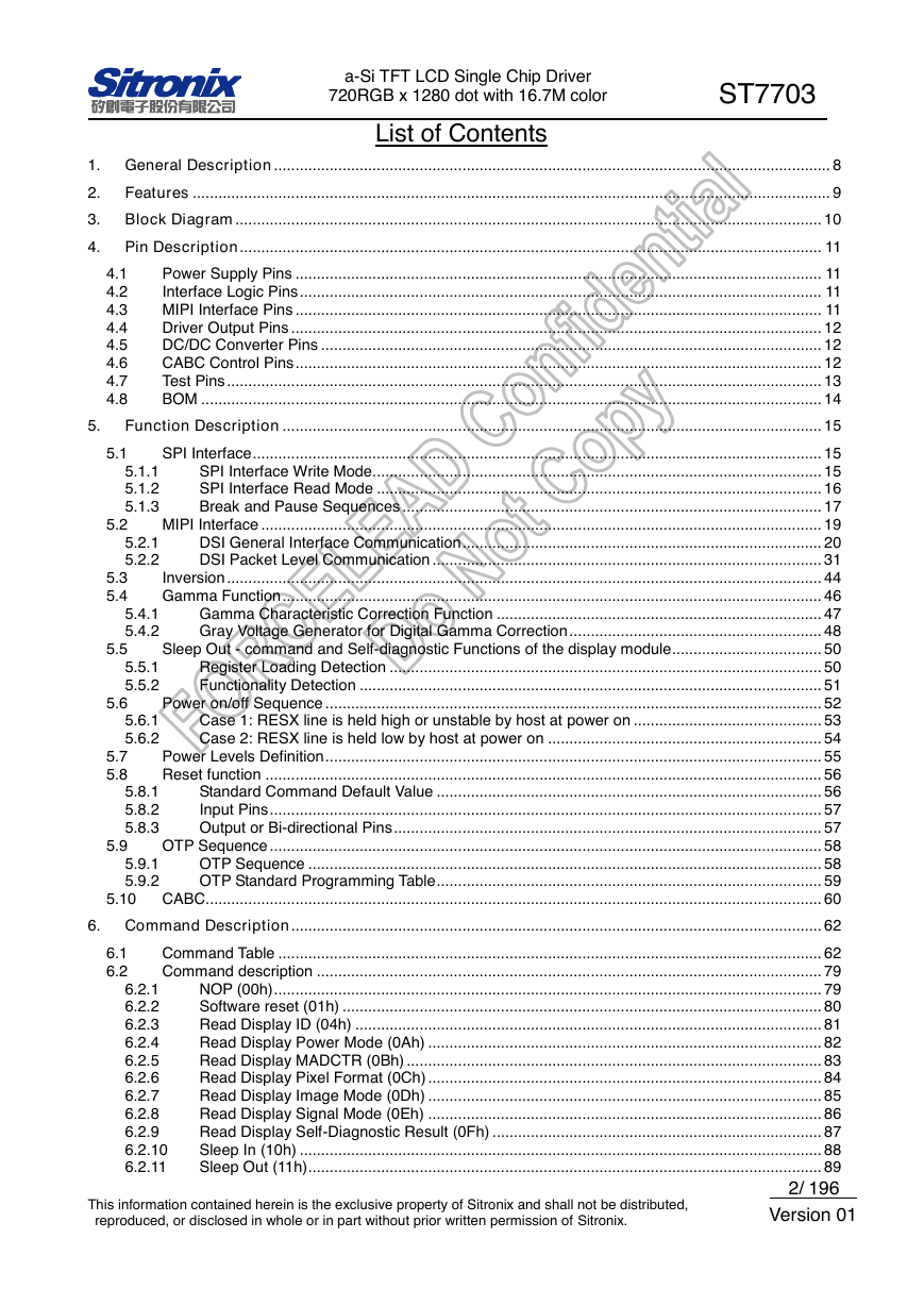
List of Contents
1. General Description .................................................................................................................................. 8
2.
Features ..................................................................................................................................................... 9
3. Block Diagram ......................................................................................................................................... 10
4. Pin Description ........................................................................................................................................ 11
4.1
4.2
4.3
4.4
4.5
4.6
4.7
4.8
Power Supply Pins ........................................................................................................................... 11
Interface Logic Pins .......................................................................................................................... 11
MIPI Interface Pins ........................................................................................................................... 11
Driver Output Pins ............................................................................................................................ 12
DC/DC Converter Pins ..................................................................................................................... 12
CABC Control Pins ........................................................................................................................... 12
Test Pins ........................................................................................................................................... 13
BOM ................................................................................................................................................. 14
5.
Function Description .............................................................................................................................. 15
5.1
5.2
5.3
5.4
5.5
5.2.1
5.2.2
5.1.1
5.1.2
5.1.3
SPI Interface ..................................................................................................................................... 15
SPI Interface Write Mode......................................................................................................... 15
SPI Interface Read Mode ........................................................................................................ 16
Break and Pause Sequences .................................................................................................. 17
MIPI Interface ................................................................................................................................... 19
DSI General Interface Communication .................................................................................... 20
DSI Packet Level Communication ........................................................................................... 31
Inversion ........................................................................................................................................... 44
Gamma Function .............................................................................................................................. 46
Gamma Characteristic Correction Function ............................................................................ 47
Gray Voltage Generator for Digital Gamma Correction ........................................................... 48
Sleep Out - command and Self-diagnostic Functions of the display module ................................... 50
Register Loading Detection ..................................................................................................... 50
Functionality Detection ............................................................................................................ 51
Power on/off Sequence .................................................................................................................... 52
Case 1: RESX line is held high or unstable by host at power on ............................................ 53
Case 2: RESX line is held low by host at power on ................................................................ 54
Power Levels Definition .................................................................................................................... 55
Reset function .................................................................................................................................. 56
Standard Command Default Value .......................................................................................... 56
Input Pins ................................................................................................................................. 57
Output or Bi-directional Pins .................................................................................................... 57
OTP Sequence ................................................................................................................................. 58
OTP Sequence ........................................................................................................................ 58
OTP Standard Programming Table .......................................................................................... 59
5.10 CABC................................................................................................................................................ 60
5.8.1
5.8.2
5.8.3
5.9.1
5.9.2
5.4.1
5.4.2
5.5.1
5.5.2
5.6.1
5.6.2
5.6
5.7
5.8
6. Command Description ............................................................................................................................ 62
5.9
6.1
6.2
Command Table ............................................................................................................................... 62
Command description ...................................................................................................................... 79
NOP (00h) ................................................................................................................................ 79
Software reset (01h) ................................................................................................................ 80
Read Display ID (04h) ............................................................................................................. 81
Read Display Power Mode (0Ah) ............................................................................................ 82
Read Display MADCTR (0Bh) ................................................................................................. 83
Read Display Pixel Format (0Ch) ............................................................................................ 84
Read Display Image Mode (0Dh) ............................................................................................ 85
Read Display Signal Mode (0Eh) ............................................................................................ 86
Read Display Self-Diagnostic Result (0Fh) ............................................................................. 87
Sleep In (10h) .......................................................................................................................... 88
Sleep Out (11h) ........................................................................................................................ 89
2/ 196
6.2.1
6.2.2
6.2.3
6.2.4
6.2.5
6.2.6
6.2.7
6.2.8
6.2.9
6.2.10
6.2.11
This information contained herein is the exclusive property of Sitronix and shall not be distributed,
reproduced, or disclosed in whole or in part without prior written permission of Sitronix.
Version 01
�
a-Si TFT LCD Single Chip Driver
720RGB x 1280 dot with 16.7M color
ST7703
6.2.12
Normal Display Mode On (13h) ............................................................................................... 91
6.2.13
Display Inversion Off (20h) ...................................................................................................... 92
6.2.14
Display Inversion On (21h) ...................................................................................................... 93
6.2.15
All Pixel Off (22h) ..................................................................................................................... 94
6.2.16
All Pixel On (23h) ..................................................................................................................... 95
6.2.17
Display Off (28h) ...................................................................................................................... 96
6.2.18
Display On (29h) ...................................................................................................................... 97
6.2.19
Memory Access Control (36h) ................................................................................................. 98
6.2.20
Idle Mode Off (38h) .................................................................................................................. 99
6.2.21
Idle Mode On (39h) ................................................................................................................ 100
6.2.22 Write Display Brightness (51h) .............................................................................................. 102
6.2.23
Read Display Brightness (52h) .............................................................................................. 103
6.2.24 Write CTRL Display (53h) ...................................................................................................... 104
6.2.25
Read CTRL Display Value (54h) ............................................................................................ 105
6.2.26 Write Content Adaptive Brightness Control (55h) .................................................................. 106
6.2.27
Read Content Adaptive Brightness Control (56h) ................................................................. 107
6.2.28 Write CABC Minimum Brightness (5Eh) ................................................................................ 108
6.2.29
Read CABC minimum brightness (5Fh) ................................................................................ 109
Read Black/White Low Bits (70h) .......................................................................................... 110
6.2.30
Read Bkx (71h) ....................................................................................................................... 111
6.2.31
Read Bky (72h) ...................................................................................................................... 112
6.2.32
Read Wx (73h) ....................................................................................................................... 113
6.2.33
6.2.34
Read Wy (74h) ....................................................................................................................... 114
Read Red/Green Low Bits (75h) ........................................................................................... 115
6.2.35
Read Rx (76h) ....................................................................................................................... 116
6.2.36
Read Ry (77h) ....................................................................................................................... 117
6.2.37
6.2.38
Read Gx (78h) ....................................................................................................................... 118
Read Gy (79h) ....................................................................................................................... 119
6.2.39
Read Blue/AColor Low Bits (7Ah) ......................................................................................... 120
6.2.40
Read Bx (7Bh) ....................................................................................................................... 121
6.2.41
6.2.42
Read By (7Ch) ....................................................................................................................... 122
Read Ax (7Dh) ....................................................................................................................... 123
6.2.43
Read Ay (7Eh) ....................................................................................................................... 124
6.2.44
Read DDB Start (A1h) ........................................................................................................... 125
6.2.45
Read DDB Continue (A8h) .................................................................................................... 127
6.2.46
6.2.47
Read ID1 Value (DAh) ........................................................................................................... 128
Read ID2 Value (DBh) ........................................................................................................... 129
6.2.48
Read ID3 Value (DCh) ........................................................................................................... 130
6.2.49
SETEXTC (B9h) .................................................................................................................... 131
6.2.50
6.2.51
SETDISP (B2h) ...................................................................................................................... 132
SETRGBIF (B3h) ................................................................................................................... 134
6.2.52
SETCYC (B4h) ...................................................................................................................... 135
6.2.53
SETBGP (B5h) ...................................................................................................................... 136
6.2.54
6.2.55
SETVCOM (B6h) ................................................................................................................... 137
SETOTP (B7h) ....................................................................................................................... 140
6.2.56
SETPOWER_EXT (B8h) ....................................................................................................... 142
6.2.57
SETMIPI (BAh) ...................................................................................................................... 144
6.2.58
SETVDC (BCh) ...................................................................................................................... 146
6.2.59
6.2.60
SETSCR (C0h) ...................................................................................................................... 147
SETPOWER (C1h) ................................................................................................................ 149
6.2.61
SETID (C3h) .......................................................................................................................... 152
6.2.62
SETDDB (C4h) ...................................................................................................................... 152
6.2.63
6.2.64
SETIO (C7h) .......................................................................................................................... 153
SETCABC (C8h) .................................................................................................................... 154
6.2.65
SETPANEL (CCh) .................................................................................................................. 154
6.2.66
DGC_R (CDh) ........................................................................................................................ 155
6.2.67
6.2.68
DGC_G (CEh) ........................................................................................................................ 156
DGC_B (CFh) ........................................................................................................................ 157
6.2.69
6.2.70
SETGAMMA (E0h)................................................................................................................. 158
This information contained herein is the exclusive property of Sitronix and shall not be distributed,
reproduced, or disclosed in whole or in part without prior written permission of Sitronix.
3/ 196
Version 01
�
a-Si TFT LCD Single Chip Driver
720RGB x 1280 dot with 16.7M color
ST7703
6.2.71
6.2.72
6.2.73
6.2.74
6.2.75
6.2.76
6.2.77
6.2.78
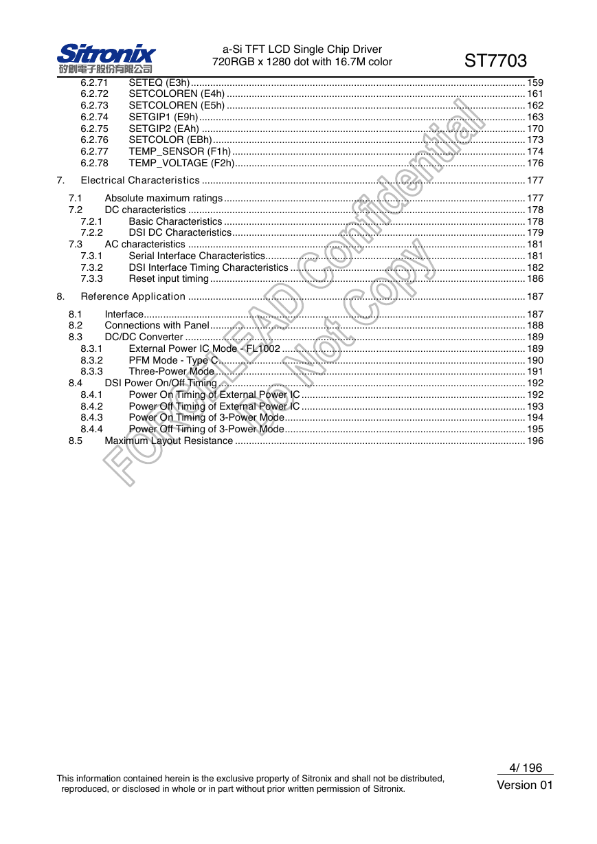
SETEQ (E3h) ......................................................................................................................... 159
SETCOLOREN (E4h) ............................................................................................................ 161
SETCOLOREN (E5h) ............................................................................................................ 162
SETGIP1 (E9h) ...................................................................................................................... 163
SETGIP2 (EAh) ..................................................................................................................... 170
SETCOLOR (EBh) ................................................................................................................. 173
TEMP_SENSOR (F1h) .......................................................................................................... 174
TEMP_VOLTAGE (F2h) ......................................................................................................... 176
7. Electrical Characteristics ..................................................................................................................... 177
7.1
7.2
7.3
Absolute maximum ratings ............................................................................................................. 177
DC characteristics .......................................................................................................................... 178
Basic Characteristics ............................................................................................................. 178
DSI DC Characteristics .......................................................................................................... 179
AC characteristics .......................................................................................................................... 181
Serial Interface Characteristics .............................................................................................. 181
DSI Interface Timing Characteristics ..................................................................................... 182
Reset input timing .................................................................................................................. 186
7.2.1
7.2.2
7.3.1
7.3.2
7.3.3
8. Reference Application .......................................................................................................................... 187
Interface.......................................................................................................................................... 187
Connections with Panel .................................................................................................................. 188
DC/DC Converter ........................................................................................................................... 189
External Power IC Mode - FL1002 ........................................................................................ 189
PFM Mode - Type C ............................................................................................................... 190
Three-Power Mode ................................................................................................................ 191
DSI Power On/Off Timing ............................................................................................................... 192
Power On Timing of External Power IC ................................................................................. 192
Power Off Timing of External Power IC ................................................................................. 193
Power On Timing of 3-Power Mode ....................................................................................... 194
Power Off Timing of 3-Power Mode ....................................................................................... 195
Maximum Layout Resistance ......................................................................................................... 196
8.3.1
8.3.2
8.3.3
8.4.1
8.4.2
8.4.3
8.4.4
8.1
8.2
8.3
8.4
8.5
This information contained herein is the exclusive property of Sitronix and shall not be distributed,
reproduced, or disclosed in whole or in part without prior written permission of Sitronix.
4/ 196
Version 01
�
a-Si TFT LCD Single Chip Driver
720RGB x 1280 dot with 16.7M color
ST7703
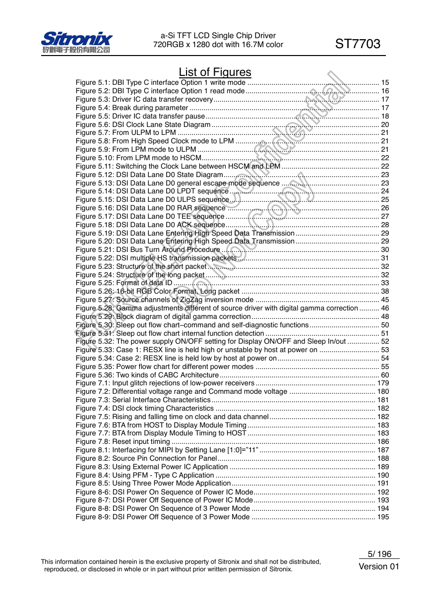
List of Figures
Figure 5.1: DBI Type C interface Option 1 write mode .................................................................. 15
Figure 5.2: DBI Type C interface Option 1 read mode ................................................................... 16
Figure 5.3: Driver IC data transfer recovery ................................................................................... 17
Figure 5.4: Break during parameter ............................................................................................... 17
Figure 5.5: Driver IC data transfer pause ....................................................................................... 18
Figure 5.6: DSI Clock Lane State Diagram .................................................................................... 20
Figure 5.7: From ULPM to LPM ..................................................................................................... 21
Figure 5.8: From High Speed Clock mode to LPM ........................................................................ 21
Figure 5.9: From LPM mode to ULPM ........................................................................................... 21
Figure 5.10: From LPM mode to HSCM ......................................................................................... 22
Figure 5.11: Switching the Clock Lane between HSCM and LPM ................................................. 22
Figure 5.12: DSI Data Lane D0 State Diagram .............................................................................. 23
Figure 5.13: DSI Data Lane D0 general escape mode sequence ................................................. 23
Figure 5.14: DSI Data Lane D0 LPDT sequence ........................................................................... 24
Figure 5.15: DSI Data Lane D0 ULPS sequence ........................................................................... 25
Figure 5.16: DSI Data Lane D0 RAR sequence ............................................................................ 26
Figure 5.17: DSI Data Lane D0 TEE sequence ............................................................................. 27
Figure 5.18: DSI Data Lane D0 ACK sequence ............................................................................. 28
Figure 5.19: DSI Data Lane Entering High Speed Data Transmission .......................................... 29
Figure 5.20: DSI Data Lane Entering High Speed Data Transmission .......................................... 29
Figure 5.21: DSI Bus Turn Around Procedure ............................................................................... 30
Figure 5.22: DSI multiple HS transmission packets ....................................................................... 31
Figure 5.23: Structure of the short packet ...................................................................................... 32
Figure 5.24: Structure of the long packet ....................................................................................... 32
Figure 5.25: Format of data ID ....................................................................................................... 33
Figure 5.26: 16-bit RGB Color Format, Long packet ..................................................................... 38
Figure 5.27: Source channels of ZigZag inversion mode .............................................................. 45
Figure 5.28: Gamma adjustments different of source driver with digital gamma correction .......... 46
Figure 5.29: Block diagram of digital gamma correction ................................................................ 48
Figure 5.30: Sleep out flow chart–command and self-diagnostic functions ................................... 50
Figure 5.31: Sleep out flow chart internal function detection ......................................................... 51
Figure 5.32: The power supply ON/OFF setting for Display ON/OFF and Sleep In/out ................ 52
Figure 5.33: Case 1: RESX line is held high or unstable by host at power on .............................. 53
Figure 5.34: Case 2: RESX line is held low by host at power on ................................................... 54
Figure 5.35: Power flow chart for different power modes .............................................................. 55
Figure 5.36: Two kinds of CABC Architecture ................................................................................ 60
Figure 7.1: Input glitch rejections of low-power receivers ............................................................ 179
Figure 7.2: Differential voltage range and Command mode voltage ........................................... 180
Figure 7.3: Serial Interface Characteristics .................................................................................. 181
Figure 7.4: DSI clock timing Characteristics ................................................................................ 182
Figure 7.5: Rising and falling time on clock and data channel ..................................................... 182
Figure 7.6: BTA from HOST to Display Module Timing ................................................................ 183
Figure 7.7: BTA from Display Module Timing to HOST ................................................................ 183
Figure 7.8: Reset input timing ...................................................................................................... 186
Figure 8.1: Interfacing for MIPI by Setting Lane [1:0]=”11” .......................................................... 187
Figure 8.2: Source Pin Connection for Panel ............................................................................... 188
Figure 8.3: Using External Power IC Application ......................................................................... 189
Figure 8.4: Using PFM - Type C Application ................................................................................ 190
Figure 8.5: Using Three Power Mode Application ........................................................................ 191
Figure 8-6: DSI Power On Sequence of Power IC Mode ............................................................. 192
Figure 8-7: DSI Power Off Sequence of Power IC Mode ............................................................. 193
Figure 8-8: DSI Power On Sequence of 3 Power Mode .............................................................. 194
Figure 8-9: DSI Power Off Sequence of 3 Power Mode .............................................................. 195
This information contained herein is the exclusive property of Sitronix and shall not be distributed,
reproduced, or disclosed in whole or in part without prior written permission of Sitronix.
5/ 196
Version 01
�
a-Si TFT LCD Single Chip Driver
720RGB x 1280 dot with 16.7M color
ST7703
List of Tables
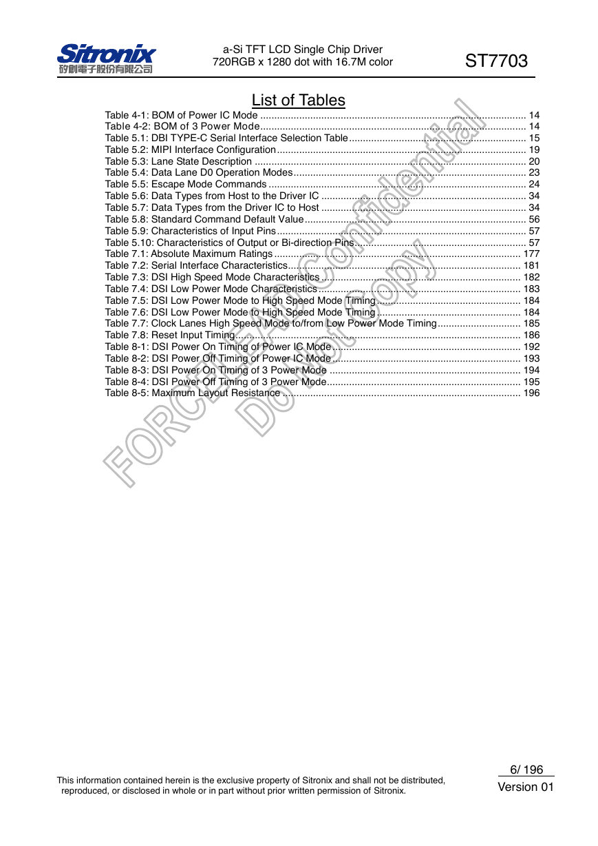
Table 4-1: BOM of Power IC Mode ................................................................................................ 14
Table 4-2: BOM of 3 Power Mode ................................................................................................ 14
Table 5.1: DBI TYPE-C Serial Interface Selection Table ................................................................ 15
Table 5.2: MIPI Interface Configuration .......................................................................................... 19
Table 5.3: Lane State Description .................................................................................................. 20
Table 5.4: Data Lane D0 Operation Modes .................................................................................... 23
Table 5.5: Escape Mode Commands ............................................................................................. 24
Table 5.6: Data Types from Host to the Driver IC .......................................................................... 34
Table 5.7: Data Types from the Driver IC to Host .......................................................................... 34
Table 5.8: Standard Command Default Value ................................................................................ 56
Table 5.9: Characteristics of Input Pins .......................................................................................... 57
Table 5.10: Characteristics of Output or Bi-direction Pins .............................................................. 57
Table 7.1: Absolute Maximum Ratings ......................................................................................... 177
Table 7.2: Serial Interface Characteristics .................................................................................... 181
Table 7.3: DSI High Speed Mode Characteristics ........................................................................ 182
Table 7.4: DSI Low Power Mode Characteristics ......................................................................... 183
Table 7.5: DSI Low Power Mode to High Speed Mode Timing .................................................... 184
Table 7.6: DSI Low Power Mode to High Speed Mode Timing .................................................... 184
Table 7.7: Clock Lanes High Speed Mode to/from Low Power Mode Timing .............................. 185
Table 7.8: Reset Input Timing ....................................................................................................... 186
Table 8-1: DSI Power On Timing of Power IC Mode .................................................................... 192
Table 8-2: DSI Power Off Timing of Power IC Mode .................................................................... 193
Table 8-3: DSI Power On Timing of 3 Power Mode ..................................................................... 194
Table 8-4: DSI Power Off Timing of 3 Power Mode...................................................................... 195
Table 8-5: Maximum Layout Resistance ...................................................................................... 196
This information contained herein is the exclusive property of Sitronix and shall not be distributed,
reproduced, or disclosed in whole or in part without prior written permission of Sitronix.
6/ 196
Version 01
�
a-Si TFT LCD Single Chip Driver
720RGB x 1280 dot with 16.7M color
ST7703
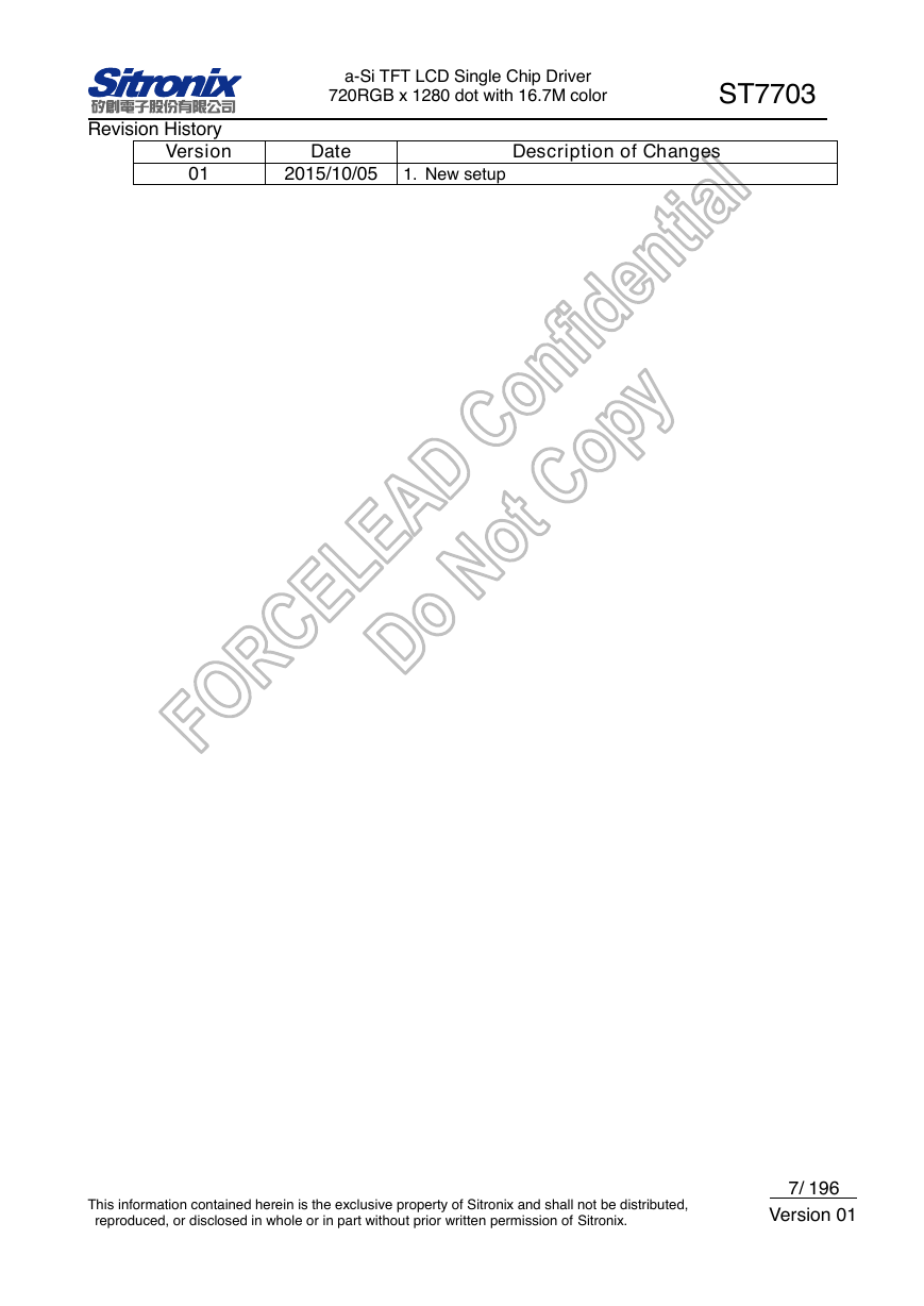
Revision History
Version
01
Date
Description of Changes
2015/10/05
1. New setup
This information contained herein is the exclusive property of Sitronix and shall not be distributed,
reproduced, or disclosed in whole or in part without prior written permission of Sitronix.
7/ 196
Version 01
�
a-Si TFT LCD Single Chip Driver
720RGB x 1280 dot with 16.7M color
ST7703
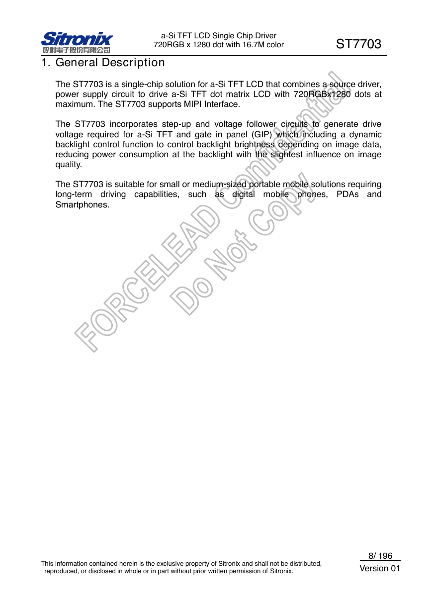
1. General Description
The ST7703 is a single-chip solution for a-Si TFT LCD that combines a source driver,
power supply circuit to drive a-Si TFT dot matrix LCD with 720RGBx1280 dots at
maximum. The ST7703 supports MIPI Interface.
The ST7703 incorporates step-up and voltage follower circuits to generate drive
voltage required for a-Si TFT and gate in panel (GIP) which including a dynamic
backlight control function to control backlight brightness depending on image data,
reducing power consumption at the backlight with the slightest influence on image
quality.
The ST7703 is suitable for small or medium-sized portable mobile solutions requiring
long-term driving capabilities, such as digital mobile phones, PDAs and
Smartphones.
This information contained herein is the exclusive property of Sitronix and shall not be distributed,
reproduced, or disclosed in whole or in part without prior written permission of Sitronix.
8/ 196
Version 01
�



 2023年江西萍乡中考道德与法治真题及答案.doc
 2012年重庆南川中考生物真题及答案.doc
 2013年江西师范大学地理学综合及文艺理论基础考研真题.doc
 2020年四川甘孜小升初语文真题及答案I卷.doc
 2020年注册岩土工程师专业基础考试真题及答案.doc
 2023-2024学年福建省厦门市九年级上学期数学月考试题及答案.doc
 2021-2022学年辽宁省沈阳市大东区九年级上学期语文期末试题及答案.doc
 2022-2023学年北京东城区初三第一学期物理期末试卷及答案.doc
 2018上半年江西教师资格初中地理学科知识与教学能力真题及答案.doc
 2012年河北国家公务员申论考试真题及答案-省级.doc
 2020-2021学年江苏省扬州市江都区邵樊片九年级上学期数学第一次质量检测试题及答案.doc
 2022下半年黑龙江教师资格证中学综合素质真题及答案.doc