C H A P T E R 1
Introduction to 3G CDMA
1.1 Third Generation Systems
While there are several wireless standards and systems that qualify as third genera-
tion (3G) systems, this book specifically deals with the IS-2000 implementation of
3G. In the mid-1990s, the International Telecommunication Union (ITU) initiated
an effort to develop a framework of standards and systems that will provide wireless
and ubiquitous telecommunications services to users anywhere at anytime. Subse-
quently, International Mobile Telecommunications-2000 (IMT-2000), a subgroup
of the ITU, published a set of performance requirements of 3G. It is useful to review
the performance requirements of a 3G wireless system, which are as follows (for
both packet-switched and circuit-switched data):
A minimum data rate of 144 Kbps in the vehicular environment;
A minimum data rate of 384 Kbps in the pedestrian environment;
A minimum data rate of 2 Mbps in the fixed indoor and picocell environment.
In addition, in all environments the system must support same data rates for
both forward and reverse links (symmetric data rates), as well as support different
data rates for both forward and reverse links (asymmetric data rates) [1].
Some standards and systems such as Universal Mobile Telephone System
(UMTS) are implemented in the new 3G spectrum (e.g., in Europe). While other
standards and systems such as IS-2000 can introduce 3G services in spectrums
already used by second generation (2G) systems (e.g., in North America). The latter
case takes into account those investments already deployed in the field where useful
and necessary [2]. The correction in the valuation of high-technology assets in early
2000 underscores the importance of making calculated infrastructure investment
while taking into account the market demand for these services. This consideration
is one reason why IS-2000 has gained popularity in the initial deployment of 3G [3].
In addition, as will be seen in later chapters of this book, IS-2000 is backward
compatible with existing 2G IS-95 systems. This backward compatibility gives
IS-2000 two important advantages. First, IS-2000 is able to support the reuse of
existing IS-95 infrastructure equipment and hence requires only incremental invest-
ment to provide 3G services. Second, because IS-2000 represents a natural technical
evolution from its predecessor, there is a lower implementation risk when transi-
tioning to 3G.
1
�
2
Introduction to 3G CDMA
1.2 Protocol Architecture
One architectural difference between the IS-2000 standard and the IS-95 standard is
that IS-2000 calls out explicitly the functions of four different protocol layers. These
layers are the physical layer, medium access control, signaling link access control,
and upper layer.
The physical layer is responsible for transmitting
Physical layer (Layer 1) [4]:
and receiving bits over the physical medium. Since the physical medium in this case
is over the air, the layer would have to convert bits into waveforms (i.e., modulation)
to enable their transmission through air. In addition to modulation, the physical
layer also carries out coding functions to perform error control functions at the bit
and frame levels.
The MAC sublayer con-
Medium access control (MAC) sublayer (Layer 2) [5]:
trols higher layers’ access to the physical medium that is shared among different
users. In this regard, MAC carries out analogous functions as a MAC entity that
controls a local area network (LAN). Whereas a LAN MAC controls different com-
puters’ access to the shared bus, the IS-2000 MAC sublayer manages the access of
different (low-speed voice and high-speed data) users to the shared air interface.
The LAC sublayer
Signaling link access control (LAC) sublayer (Layer 2) [6]:
is responsible for the reliability of signaling (or overhead) messages that are
exchanged. Recall that the over-the-air medium is extremely error-prone, and infor-
mation messages are at times received (and accepted) with errors. On the other
hand, since signaling messages provide important control functions, these messages
have to be reliably transmitted and received. The LAC sublayer performs a set of
functions that ensure the reliable delivery of signaling messages.
The upper layer carries out the overall control of the
Upper layer (Layer 3) [7]:
IS-2000 system. It exercises this control by serving as the point that processes all and
originates new signaling messages. The information (both data and voice) messages
are also passed through Layer 3.
Recall that the IS-95 standard does not explicitly and separately describe the
functions of each layer. However in IS-95 those functions that are carried out by the
layers do exist. For example, in IS-95 mobile access is logically a function of the
MAC sublayer, but its descriptions are lumped together with the other functions
within a single standard.
At this point the reader may ask why the layered architecture was not employed
in IS-95 but now used in IS-2000. The layered architecture is now used in IS-2000
because it brings the system into conformance with the 3G architecture delineated in
IMT-2000. The IMT-2000 framework calls for different networks to cooperate to
provide services to end users, and the level and extent of these cooperation are more
clearly organized if viewed from the perspective of the layered architecture. Well-
defined layer functions provide modularity to the system. As long as a layer still per-
forms its functions and provides the expected services, the specific implementation
�
1.3 Other Elements of Protocol Architecture
3
of its functions can be modified or replaced without requiring changes to the layers
above and below it [8].
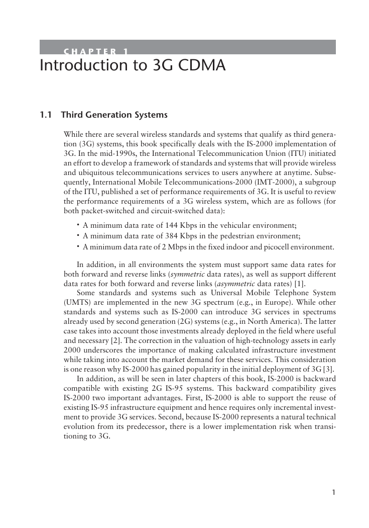
Figure 1.1 shows the structure of the protocol architecture used by IS-2000.
Without a loss of generality, this figure is shown from the perspective of the mobile
station; a similar figure can also be drawn from the perspective of the base station by
reversing the direction of some arrows and changing the placement of some entities.
Figure 1.1 is a rather important figure and we will refer to it from time to time
throughout the book. For now, note the three different layers (Layers 1, 2, and 3),
the two sublayers in Layer 2 (MAC and LAC), the entities in the layers [e.g., Signal-
ing Radio Burst Protocol (SRBP)], and the communication paths among the layers
and entities. Also note that the layer structure shown in Figure 1.1 resembles that of
the Open Systems Interconnection (OSI) Reference Model [9].
1.3 Other Elements of Protocol Architecture
In addition to the individual layers themselves, other important elements of the pro-
tocol architecture are described as follows:
The physical channels are the communication paths between
Physical channels:
the physical layer and the common/dedicated channel multiplex sublayers. The
physical channels are designated by uppercase letters. In the designation, the first
3
r
e
y
a
L
s
r
e
y
a
l
r
e
p
p
U
r
e
y
a
b
u
s
l
C
A
L
2
r
e
y
a
L
r
e
y
a
b
u
s
l
C
A
M
Data burst
Signaling
Data burst
Data
services
Voice
services
i
e
c
o
v
h
c
t
d
-
r
i
e
c
o
v
h
c
t
d
-
f
U
D
P
3
L
U
D
P
3
L
U
D
S
U
D
S
P
L
R
P
L
R
Signaling LAC
U
D
P
C
A
L
SRBP
h
c
s
c
-
r
h
c
s
c
-
f
h
c
s
c
-
f
h
c
s
d
-
r
h
c
s
d
-
f
RLP
h
c
t
d
-
r
h
c
t
d
-
f
Common channel
multiplex sublayer
Dedicated channel
multiplex sublayer
H
C
A
E
-
R
H
C
A
-
R
H
C
C
C
-
R
H
C
N
Y
S
-
F
H
C
C
P
C
-
F
H
C
A
C
-
F
H
C
C
C
-
F
H
C
C
B
-
F
H
C
P
-
F
H
C
F
-
R
H
C
C
D
-
R
H
C
S
-
R
H
C
C
D
-
F
H
C
F
-
F
H
C
S
-
F
Reverse link: coding and modulation
Forward link: demodulation and decoding
1
r
e
y
a
L
r
e
y
a
l
l
a
c
i
s
y
h
P
RL
FL
Figure 1.1 Structure of the protocol architecture used by IS-2000. (Note that this structure is
shown from the perspective of the mobile station. After: [5].)
�
4
Introduction to 3G CDMA
letter and the dash stand for either forward link (F-) or reverse link (R-), and the last
two letters “CH” always stand for “channel.” For example, R-ACH stands for
reverse access channel, and F-FCH stands for forward fundamental channel. A list
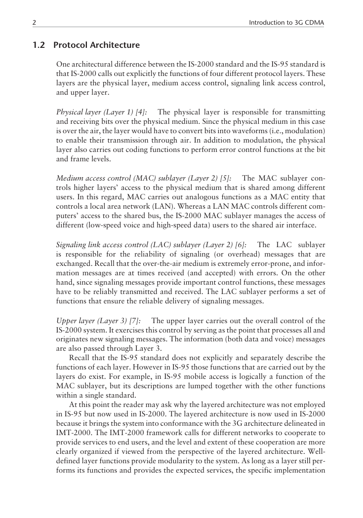
of physical channel names and their designations is shown in Table 1.1; note that
legacy IS-95 physical channels are denoted with asterisks.
The logical channels are the communication paths between the
Logical channels:
common/dedicated channel multiplex sublayers and higher layer entities. One can
think of logical channels as carrying the logical units of signaling or user informa-
tion. Contrast those with physical channels which can be thought of as the actual
physical vehicles that transport the signaling or user information over the air.
The logical channels are designated by lower-case letters. The first letter and the
dash stand for either forward link (f-) or reverse link (r-), and the last two letters
“ch” always stand for “channel.” For example, r-csch stands for reverse common
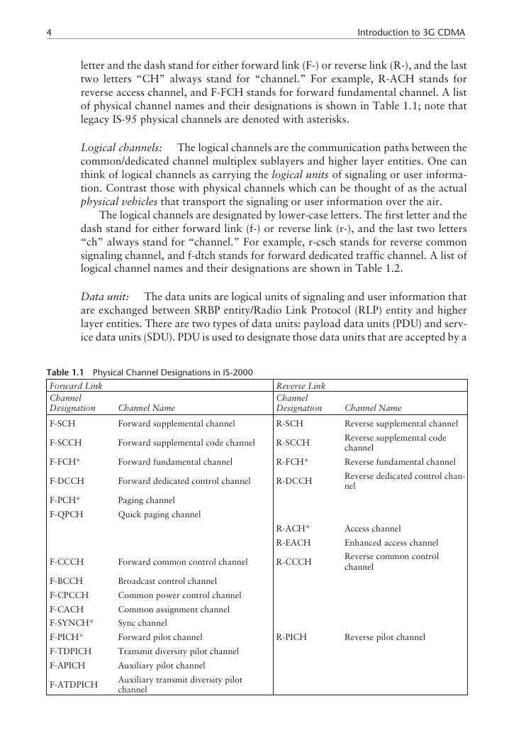
signaling channel, and f-dtch stands for forward dedicated traffic channel. A list of
logical channel names and their designations are shown in Table 1.2.
The data units are logical units of signaling and user information that
Data unit:
are exchanged between SRBP entity/Radio Link Protocol (RLP) entity and higher
layer entities. There are two types of data units: payload data units (PDU) and serv-
ice data units (SDU). PDU is used to designate those data units that are accepted by a
Table 1.1 Physical Channel Designations in IS-2000
Forward Link
Channel
Designation
F-SCH
Channel Name
Forward supplemental channel
Reverse Link
Channel
Designation
R-SCH
F-SCCH
F-FCH*
F-DCCH
F-PCH*
F-QPCH
Forward supplemental code channel
R-SCCH
Forward fundamental channel
R-FCH*
Forward dedicated control channel
R-DCCH
Paging channel
Quick paging channel
R-ACH*
R-EACH
F-CCCH
Forward common control channel
R-CCCH
Channel Name
Reverse supplemental channel
Reverse supplemental code
channel
Reverse fundamental channel
Reverse dedicated control chan-
nel
Access channel
Enhanced access channel
Reverse common control
channel
F-BCCH
F-CPCCH
F-CACH
F-SYNCH*
F-PICH*
F-TDPICH
F-APICH
F-ATDPICH
Broadcast control channel
Common power control channel
Common assignment channel
Sync channel
Forward pilot channel
Transmit diversity pilot channel
Auxiliary pilot channel
Auxiliary transmit diversity pilot
channel
R-PICH
Reverse pilot channel
�
1.4 Spreading Rate 1 and Spreading Rate 3
5
Table 1.2
Forward Link
Channel
Designation
Logical Channel Designations in IS-2000
Channel Name
Reverse Link
Channel
Designation
f-csch
f-dsch
f-dtch
Forward common signaling channel
r-csch
Forward dedicated signaling channel
r-dsch
Forward dedicated traffic channel
r-dtch
Channel Name
Reverse common signaling
channel
Reverse dedicated signaling
channel
Reverse dedicated traffic channel
provider of service from a requester of service, and SDU those data units that are
given to a provider of service by a requester of service1. The use of PDUs and SDUs is
discussed in more detail later in Chapter 4 (medium access control), Chapter 5 (link
access control), and Chapter 6 (upper layer signaling).
In the MAC sublayer, there are four different entities: SRBP, RLP, common
channel multiplex sublayer, and dedicated channel multiplex sublayer. Common
channel multiplex sublayer performs the mapping between the logical com-
mon channels (channels that are shared among multiple users) and the physical
common channels. Dedicated channel multiplex sublayer performs the mapping
between the logical dedicated channels (channels that are dedicated to specific
users) and the physical dedicated channels. Note that while dedicated channels
can be used for both signaling and user data, common channels are only used
for signaling.
SRBP and RLP are protocol entities in the MAC sublayer. They are described in
more detail in Chapter 4. It suffices to say now that SRBP handles common-channel
signaling (as opposed to dedicated-channel signaling) and RLP handles user infor-
mation that is packetized in nature.
1.4 Spreading Rate 1 and Spreading Rate 3
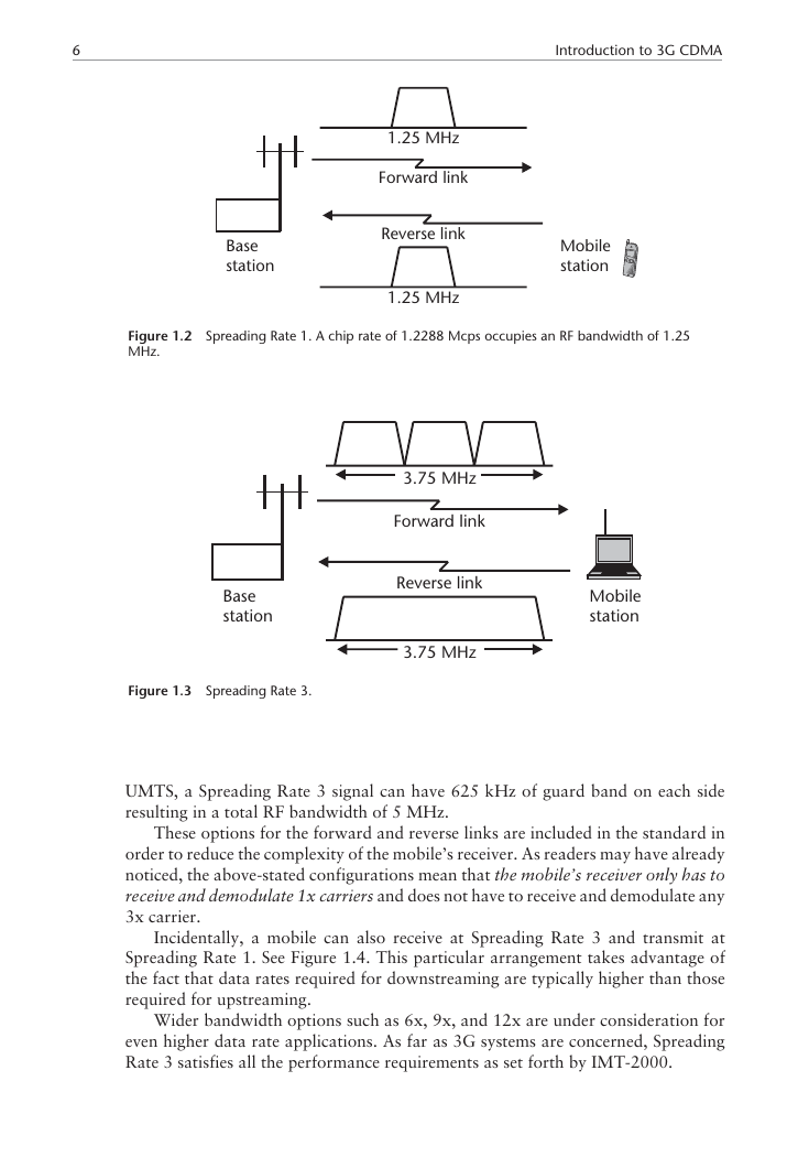
Without a loss of generality, this book will focus on Spreading Rate 1 (also known
as “1x”) of IS-2000. Spreading Rate 1 by definition uses one times the chip rate of
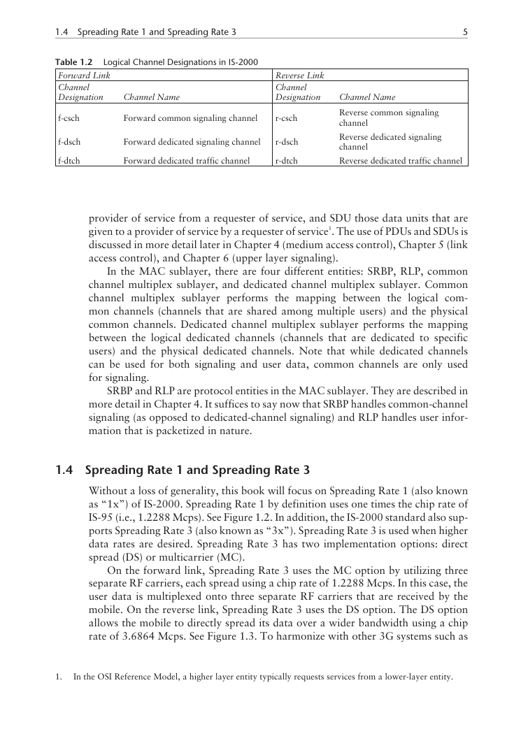
IS-95 (i.e., 1.2288 Mcps). See Figure 1.2. In addition, the IS-2000 standard also sup-
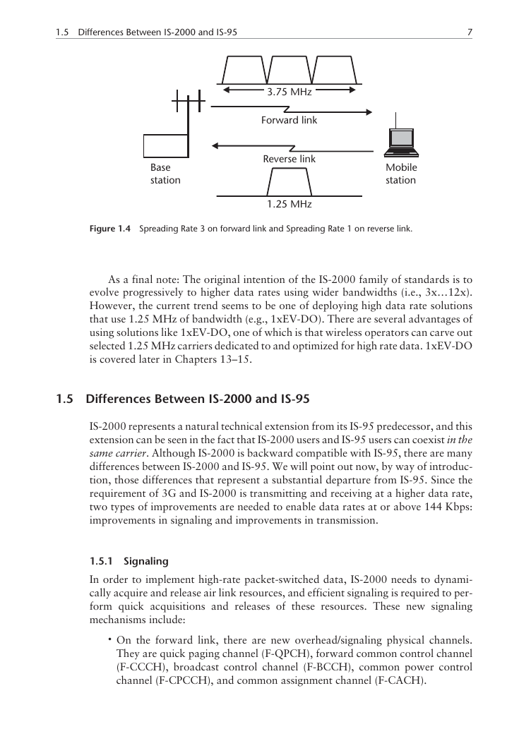
ports Spreading Rate 3 (also known as “3x”). Spreading Rate 3 is used when higher
data rates are desired. Spreading Rate 3 has two implementation options: direct
spread (DS) or multicarrier (MC).
On the forward link, Spreading Rate 3 uses the MC option by utilizing three
separate RF carriers, each spread using a chip rate of 1.2288 Mcps. In this case, the
user data is multiplexed onto three separate RF carriers that are received by the
mobile. On the reverse link, Spreading Rate 3 uses the DS option. The DS option
allows the mobile to directly spread its data over a wider bandwidth using a chip
rate of 3.6864 Mcps. See Figure 1.3. To harmonize with other 3G systems such as
1.
In the OSI Reference Model, a higher layer entity typically requests services from a lower-layer entity.
�
6
Introduction to 3G CDMA
1.25 MHz
Forward link
Reverse link
1.25 MHz
Mobile
station
Base
station
Figure 1.2 Spreading Rate 1. A chip rate of 1.2288 Mcps occupies an RF bandwidth of 1.25
MHz.
3.75 MHz
Forward link
Reverse link
3.75 MHz
Mobile
station
Base
station
Figure 1.3 Spreading Rate 3.
UMTS, a Spreading Rate 3 signal can have 625 kHz of guard band on each side
resulting in a total RF bandwidth of 5 MHz.
These options for the forward and reverse links are included in the standard in
order to reduce the complexity of the mobile’s receiver. As readers may have already
noticed, the above-stated configurations mean that the mobile’s receiver only has to
receive and demodulate 1x carriers and does not have to receive and demodulate any
3x carrier.
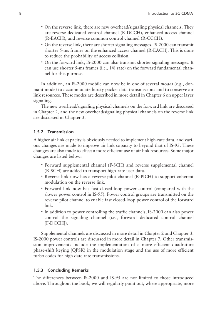
Incidentally, a mobile can also receive at Spreading Rate 3 and transmit at
Spreading Rate 1. See Figure 1.4. This particular arrangement takes advantage of
the fact that data rates required for downstreaming are typically higher than those
required for upstreaming.
Wider bandwidth options such as 6x, 9x, and 12x are under consideration for
even higher data rate applications. As far as 3G systems are concerned, Spreading
Rate 3 satisfies all the performance requirements as set forth by IMT-2000.
�
1.5 Differences Between IS-2000 and IS-95
7
3.75 MHz
Forward link
Reverse link
1.25 MHz
Mobile
station
Base
station
Figure 1.4 Spreading Rate 3 on forward link and Spreading Rate 1 on reverse link.
As a final note: The original intention of the IS-2000 family of standards is to
evolve progressively to higher data rates using wider bandwidths (i.e., 3x…12x).
However, the current trend seems to be one of deploying high data rate solutions
that use 1.25 MHz of bandwidth (e.g., 1xEV-DO). There are several advantages of
using solutions like 1xEV-DO, one of which is that wireless operators can carve out
selected 1.25 MHz carriers dedicated to and optimized for high rate data. 1xEV-DO
is covered later in Chapters 13–15.
1.5 Differences Between IS-2000 and IS-95
IS-2000 represents a natural technical extension from its IS-95 predecessor, and this
extension can be seen in the fact that IS-2000 users and IS-95 users can coexist in the
same carrier. Although IS-2000 is backward compatible with IS-95, there are many
differences between IS-2000 and IS-95. We will point out now, by way of introduc-
tion, those differences that represent a substantial departure from IS-95. Since the
requirement of 3G and IS-2000 is transmitting and receiving at a higher data rate,
two types of improvements are needed to enable data rates at or above 144 Kbps:
improvements in signaling and improvements in transmission.
1.5.1 Signaling
In order to implement high-rate packet-switched data, IS-2000 needs to dynami-
cally acquire and release air link resources, and efficient signaling is required to per-
form quick acquisitions and releases of these resources. These new signaling
mechanisms include:
On the forward link, there are new overhead/signaling physical channels.
They are quick paging channel (F-QPCH), forward common control channel
(F-CCCH), broadcast control channel (F-BCCH), common power control
channel (F-CPCCH), and common assignment channel (F-CACH).
�
8
Introduction to 3G CDMA
On the reverse link, there are new overhead/signaling physical channels. They
are reverse dedicated control channel (R-DCCH), enhanced access channel
(R-EACH), and reverse common control channel (R-CCCH).
On the reverse link, there are shorter signaling messages. IS-2000 can transmit
shorter 5-ms frames on the enhanced access channel (R-EACH). This is done
to reduce the probability of access collision.
On the forward link, IS-2000 can also transmit shorter signaling messages. It
can use shorter 5-ms frames (i.e., 1/8 rate) on the forward fundamental chan-
nel for this purpose.
In addition, an IS-2000 mobile can now be in one of several modes (e.g., dor-
mant mode) to accommodate bursty packet data transmissions and to conserve air
link resources. These modes are described in more detail in Chapter 6 on upper layer
signaling.
The new overhead/signaling physical channels on the forward link are discussed
in Chapter 2, and the new overhead/signaling physical channels on the reverse link
are discussed in Chapter 3.
1.5.2 Transmission
A higher air link capacity is obviously needed to implement high-rate data, and vari-
ous changes are made to improve air link capacity to beyond that of IS-95. These
changes are also made to effect a more efficient use of air link resources. Some major
changes are listed below:
Forward supplemental channel (F-SCH) and reverse supplemental channel
(R-SCH) are added to transport high-rate user data.
Reverse link now has a reverse pilot channel (R-PICH) to support coherent
modulation on the reverse link.
Forward link now has fast closed-loop power control (compared with the
slower power control in IS-95). Power control groups are transmitted on the
reverse pilot channel to enable fast closed-loop power control of the forward
link.
In addition to power controlling the traffic channels, IS-2000 can also power
forward dedicated control channel
the signaling channel
control
[F-DCCH]).
(i.e.,
Supplemental channels are discussed in more detail in Chapter 2 and Chapter 3.
IS-2000 power controls are discussed in more detail in Chapter 7. Other transmis-
sion improvements include the implementation of a more efficient quadrature
phase-shift keying (QPSK) in the modulation stage and the use of more efficient
turbo codes for high date rate transmissions.
1.5.3 Concluding Remarks
The differences between IS-2000 and IS-95 are not limited to those introduced
above. Throughout the book, we will regularly point out, where appropriate, more
�



 2023年江西萍乡中考道德与法治真题及答案.doc
 2012年重庆南川中考生物真题及答案.doc
 2013年江西师范大学地理学综合及文艺理论基础考研真题.doc
 2020年四川甘孜小升初语文真题及答案I卷.doc
 2020年注册岩土工程师专业基础考试真题及答案.doc
 2023-2024学年福建省厦门市九年级上学期数学月考试题及答案.doc
 2021-2022学年辽宁省沈阳市大东区九年级上学期语文期末试题及答案.doc
 2022-2023学年北京东城区初三第一学期物理期末试卷及答案.doc
 2018上半年江西教师资格初中地理学科知识与教学能力真题及答案.doc
 2012年河北国家公务员申论考试真题及答案-省级.doc
 2020-2021学年江苏省扬州市江都区邵樊片九年级上学期数学第一次质量检测试题及答案.doc
 2022下半年黑龙江教师资格证中学综合素质真题及答案.doc