1Gbit Serial NAND Flash Memory
ATO25D1GA
3.3V 1G-BIT
Serial NAND Flash Memory with Quad SPI
�
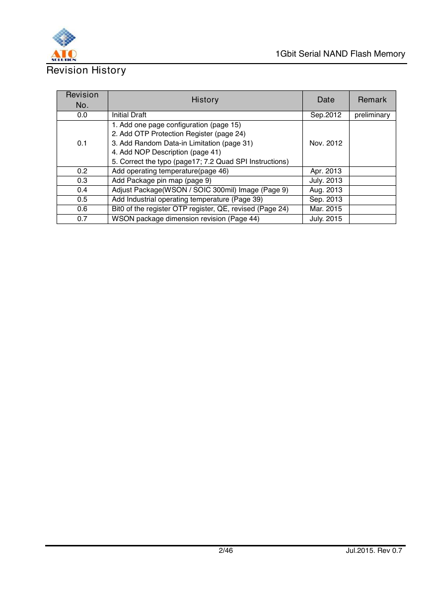
Revision History
1Gbit Serial NAND Flash Memory
Revision
No.
0.0
0.1
0.2
0.3
0.4
0.5
0.6
0.7
History
Date
Remark
Initial Draft
1. Add one page configuration (page 15)
2. Add OTP Protection Register (page 24)
3. Add Random Data-in Limitation (page 31)
4. Add NOP Description (page 41)
5. Correct the typo (page17; 7.2 Quad SPI Instructions)
Add operating temperature(page 46)
Add Package pin map (page 9)
Adjust Package(WSON / SOIC 300mil) Image (Page 9)
Add Industrial operating temperature (Page 39)
Bit0 of the register OTP register, QE, revised (Page 24)
WSON package dimension revision (Page 44)
Sep.2012
preliminary
Nov. 2012
Apr. 2013
July. 2013
Aug. 2013
Sep. 2013
Mar. 2015
July. 2015
2/46 Jul.2015. Rev 0.7
�
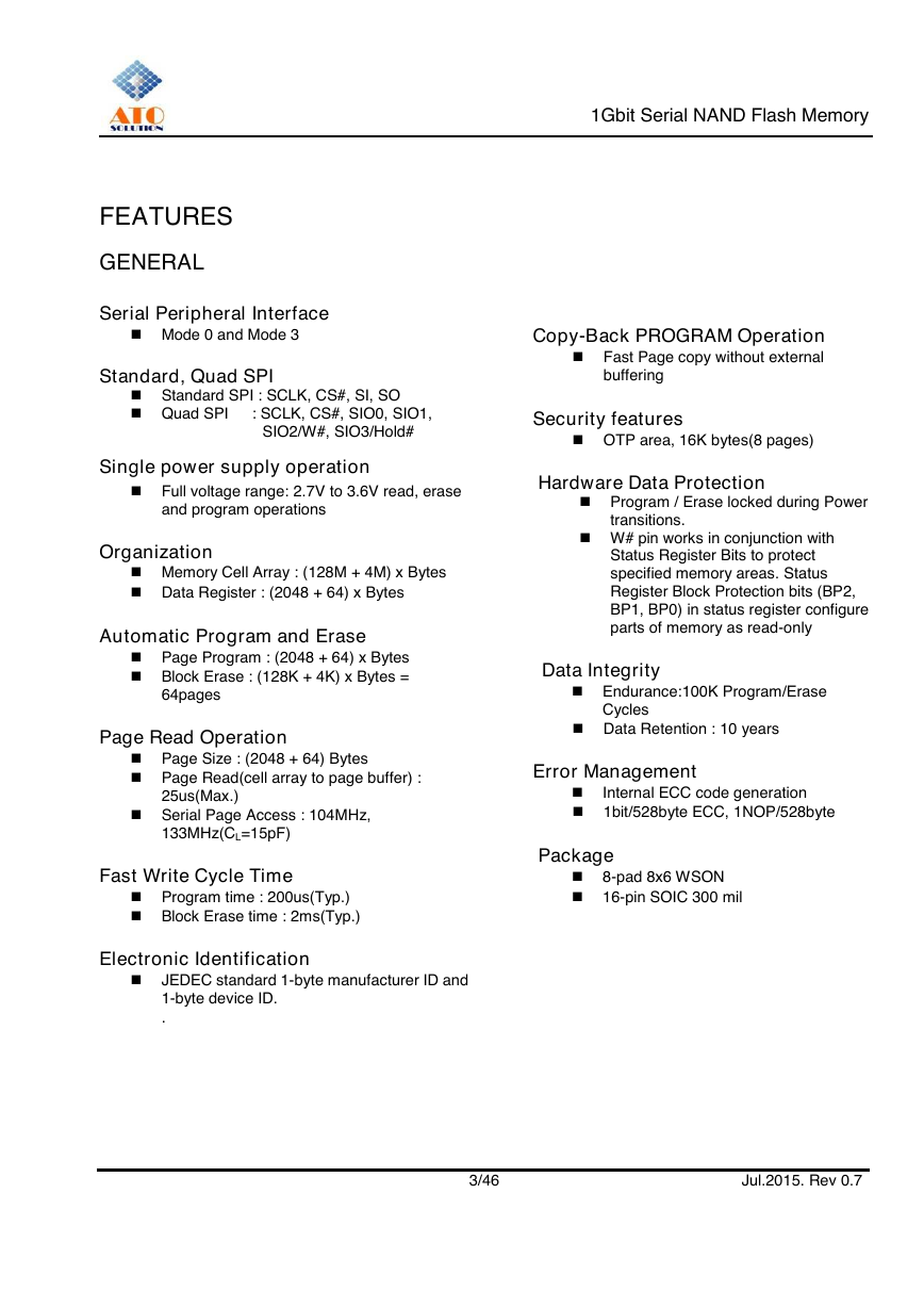
FEATURES
GENERAL
Serial Peripheral Interface
Mode 0 and Mode 3
Standard, Quad SPI
Standard SPI : SCLK, CS#, SI, SO
Quad SPI : SCLK, CS#, SIO0, SIO1,
SIO2/W#, SIO3/Hold#
Single power supply operation
Full voltage range: 2.7V to 3.6V read, erase
and program operations
Organization
Memory Cell Array : (128M + 4M) x Bytes
Data Register : (2048 + 64) x Bytes
Automatic Program and Erase
Page Program : (2048 + 64) x Bytes
Block Erase : (128K + 4K) x Bytes =
64pages
Page Read Operation
Page Size : (2048 + 64) Bytes
Page Read(cell array to page buffer) :
25us(Max.)
Serial Page Access : 104MHz,
133MHz(CL=15pF)
Fast Write Cycle Time
Program time : 200us(Typ.)
Block Erase time : 2ms(Typ.)
Electronic Identification
JEDEC standard 1-byte manufacturer ID and
1-byte device ID.
.
1Gbit Serial NAND Flash Memory
Copy-Back PROGRAM Operation
Fast Page copy without external
buffering
Security features
OTP area, 16K bytes(8 pages)
Hardware Data Protection
Program / Erase locked during Power
transitions.
W# pin works in conjunction with
Status Register Bits to protect
specified memory areas. Status
Register Block Protection bits (BP2,
BP1, BP0) in status register configure
parts of memory as read-only
Data Integrity
Endurance:100K Program/Erase
Cycles
Data Retention : 10 years
Error Management
Internal ECC code generation
1bit/528byte ECC, 1NOP/528byte
Package
8-pad 8x6 WSON
16-pin SOIC 300 mil
3/46 Jul.2015. Rev 0.7
�
1Gbit Serial NAND Flash Memory
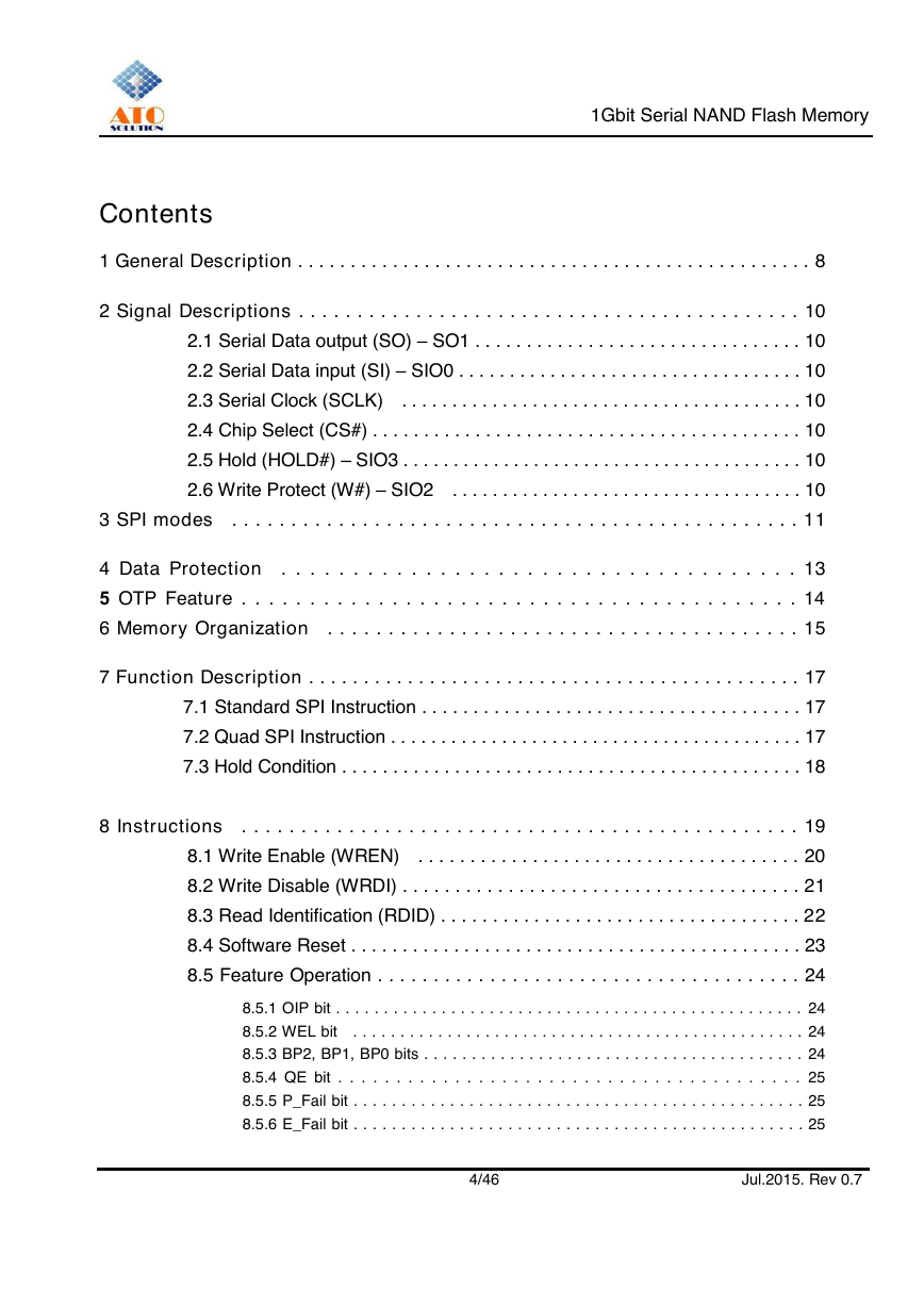
Contents
1 General Description . . . . . . . . . . . . . . . . . . . . . . . . . . . . . . . . . . . . . . . . . . . . . . . . . 8
2 Signal Descriptions . . . . . . . . . . . . . . . . . . . . . . . . . . . . . . . . . . . . . . . . . . . 10
2.1 Serial Data output (SO) – SO1 . . . . . . . . . . . . . . . . . . . . . . . . . . . . . . . . 10
2.2 Serial Data input (SI) – SIO0 . . . . . . . . . . . . . . . . . . . . . . . . . . . . . . . . . . 10
2.3 Serial Clock (SCLK) . . . . . . . . . . . . . . . . . . . . . . . . . . . . . . . . . . . . . . . . 10
2.4 Chip Select (CS#) . . . . . . . . . . . . . . . . . . . . . . . . . . . . . . . . . . . . . . . . . . 10
2.5 Hold (HOLD#) – SIO3 . . . . . . . . . . . . . . . . . . . . . . . . . . . . . . . . . . . . . . . . 10
2.6 Write Protect (W#) – SIO2 . . . . . . . . . . . . . . . . . . . . . . . . . . . . . . . . . . . 10
3 SPI modes . . . . . . . . . . . . . . . . . . . . . . . . . . . . . . . . . . . . . . . . . . . . . . . . 11
4 Data Protection . . . . . . . . . . . . . . . . . . . . . . . . . . . . . . . . . . . . 13
5 OTP Feature . . . . . . . . . . . . . . . . . . . . . . . . . . . . . . . . . . . . . . . . . 14
6 Memory Organization . . . . . . . . . . . . . . . . . . . . . . . . . . . . . . . . . . . . . . . 15
7 Function Description . . . . . . . . . . . . . . . . . . . . . . . . . . . . . . . . . . . . . . . . . . . . . 17
7.1 Standard SPI Instruction . . . . . . . . . . . . . . . . . . . . . . . . . . . . . . . . . . . . . 17
7.2 Quad SPI Instruction . . . . . . . . . . . . . . . . . . . . . . . . . . . . . . . . . . . . . . . . . 17
7.3 Hold Condition . . . . . . . . . . . . . . . . . . . . . . . . . . . . . . . . . . . . . . . . . . . . . 18
8 Instructions . . . . . . . . . . . . . . . . . . . . . . . . . . . . . . . . . . . . . . . . . . . . . . . 19
8.1 Write Enable (WREN) . . . . . . . . . . . . . . . . . . . . . . . . . . . . . . . . . . . . . 20
8.2 Write Disable (WRDI) . . . . . . . . . . . . . . . . . . . . . . . . . . . . . . . . . . . . . . 21
8.3 Read Identification (RDID) . . . . . . . . . . . . . . . . . . . . . . . . . . . . . . . . . . . 22
8.4 Software Reset . . . . . . . . . . . . . . . . . . . . . . . . . . . . . . . . . . . . . . . . . . . . 23
8.5 Feature Operation . . . . . . . . . . . . . . . . . . . . . . . . . . . . . . . . . . . . . . 24
8.5.1 OIP bit . . . . . . . . . . . . . . . . . . . . . . . . . . . . . . . . . . . . . . . . . . . . . . . . . 24
8.5.2 WEL bit . . . . . . . . . . . . . . . . . . . . . . . . . . . . . . . . . . . . . . . . . . . . . . . . 24
8.5.3 BP2, BP1, BP0 bits . . . . . . . . . . . . . . . . . . . . . . . . . . . . . . . . . . . . . . . . 24
8.5.4 QE bit . . . . . . . . . . . . . . . . . . . . . . . . . . . . . . . . . . . . . . . . 25
8.5.5 P_Fail bit . . . . . . . . . . . . . . . . . . . . . . . . . . . . . . . . . . . . . . . . . . . . . . . 25
8.5.6 E_Fail bit . . . . . . . . . . . . . . . . . . . . . . . . . . . . . . . . . . . . . . . . . . . . . . . 25
4/46
Jul.2015. Rev 0.7
�
1Gbit Serial NAND Flash Memory
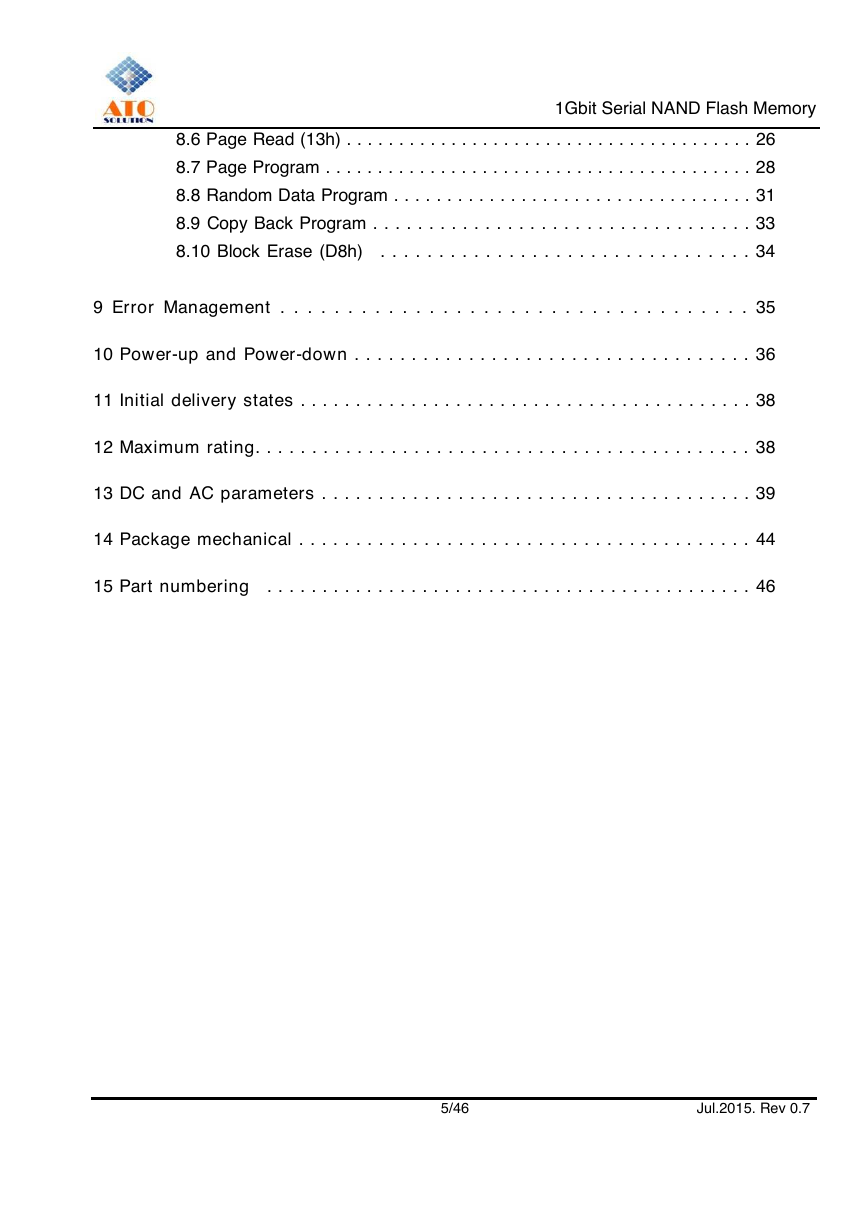
8.6 Page Read (13h) . . . . . . . . . . . . . . . . . . . . . . . . . . . . . . . . . . . . . . . 26
8.7 Page Program . . . . . . . . . . . . . . . . . . . . . . . . . . . . . . . . . . . . . . . . . 28
8.8 Random Data Program . . . . . . . . . . . . . . . . . . . . . . . . . . . . . . . . . . 31
8.9 Copy Back Program . . . . . . . . . . . . . . . . . . . . . . . . . . . . . . . . . . 33
8.10 Block Erase (D8h) . . . . . . . . . . . . . . . . . . . . . . . . . . . . . . . . 34
9 Error Management . . . . . . . . . . . . . . . . . . . . . . . . . . . . . . . . . . . 35
10 Power-up and Power-down . . . . . . . . . . . . . . . . . . . . . . . . . . . . . . . . . . . 36
11 Initial delivery states . . . . . . . . . . . . . . . . . . . . . . . . . . . . . . . . . . . . . . . . . 38
12 Maximum rating. . . . . . . . . . . . . . . . . . . . . . . . . . . . . . . . . . . . . . . . . . . . 38
13 DC and AC parameters . . . . . . . . . . . . . . . . . . . . . . . . . . . . . . . . . . . . . . 39
14 Package mechanical . . . . . . . . . . . . . . . . . . . . . . . . . . . . . . . . . . . . . . . . 44
15 Part numbering . . . . . . . . . . . . . . . . . . . . . . . . . . . . . . . . . . . . . . . . . . . . 46
5/46 Jul.2015. Rev 0.7
�
1Gbit Serial NAND Flash Memory
List of tables
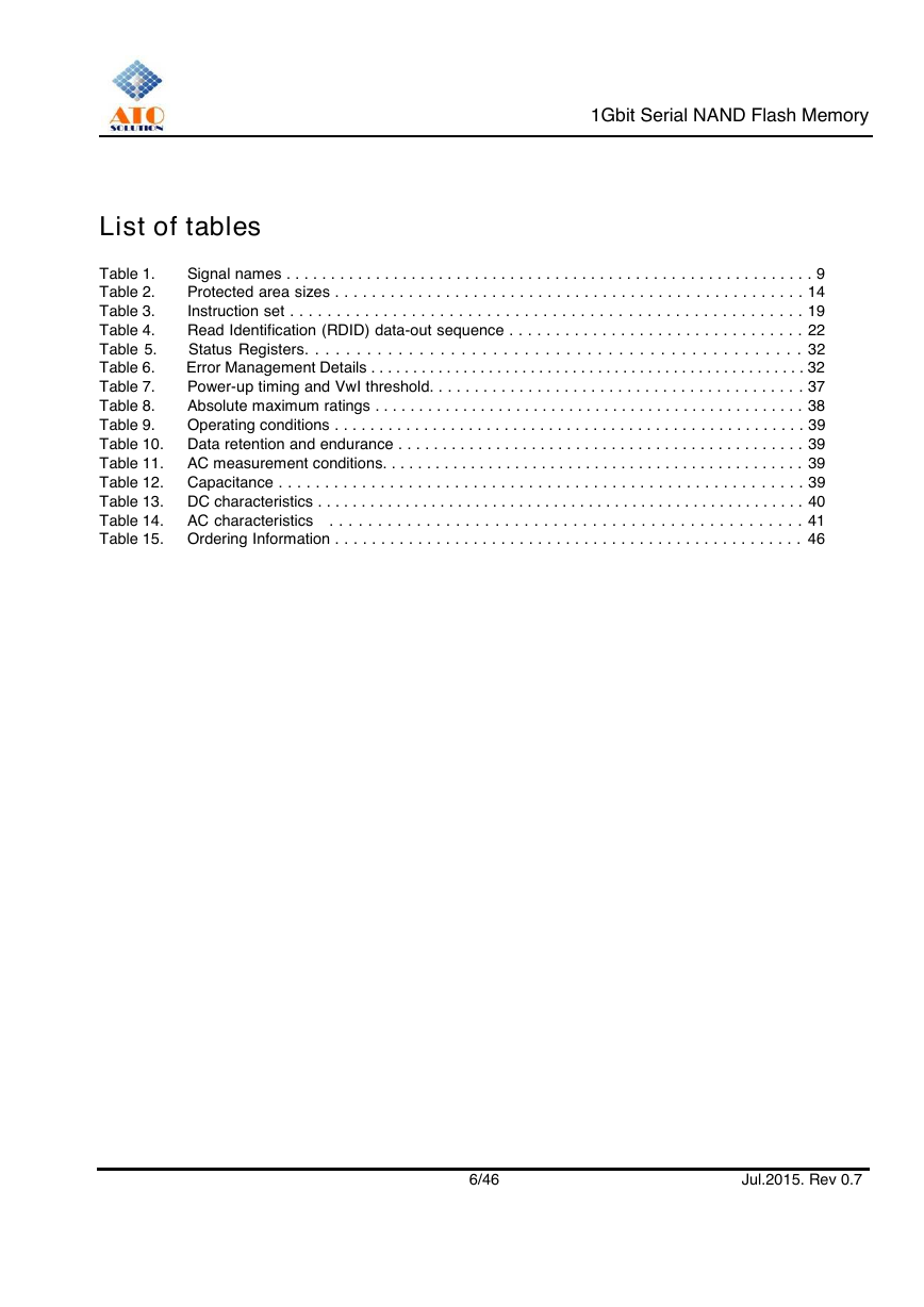
Table 1. Signal names . . . . . . . . . . . . . . . . . . . . . . . . . . . . . . . . . . . . . . . . . . . . . . . . . . . . . . . . . . . 9
Protected area sizes . . . . . . . . . . . . . . . . . . . . . . . . . . . . . . . . . . . . . . . . . . . . . . . . . . . 14
Table 2.
Table 3.
Instruction set . . . . . . . . . . . . . . . . . . . . . . . . . . . . . . . . . . . . . . . . . . . . . . . . . . . . . . . 19
Table 4. Read Identification (RDID) data-out sequence . . . . . . . . . . . . . . . . . . . . . . . . . . . . . . . . 22
Table 5. Status Registers. . . . . . . . . . . . . . . . . . . . . . . . . . . . . . . . . . . . . . . . . . . . . . . . 32
Table 6. Error Management Details . . . . . . . . . . . . . . . . . . . . . . . . . . . . . . . . . . . . . . . . . . . . . . . . . . . . 32
Table 7.
Power-up timing and VwI threshold. . . . . . . . . . . . . . . . . . . . . . . . . . . . . . . . . . . . . . . . . . 37
Table 8. Absolute maximum ratings . . . . . . . . . . . . . . . . . . . . . . . . . . . . . . . . . . . . . . . . . . . . . . . . . 38
Table 9. Operating conditions . . . . . . . . . . . . . . . . . . . . . . . . . . . . . . . . . . . . . . . . . . . . . . . . . . . . . 39
Table 10. Data retention and endurance . . . . . . . . . . . . . . . . . . . . . . . . . . . . . . . . . . . . . . . . . . . . . . 39
Table 11. AC measurement conditions. . . . . . . . . . . . . . . . . . . . . . . . . . . . . . . . . . . . . . . . . . . . . . . . 39
Table 12. Capacitance . . . . . . . . . . . . . . . . . . . . . . . . . . . . . . . . . . . . . . . . . . . . . . . . . . . . . . . . . 39
Table 13. DC characteristics . . . . . . . . . . . . . . . . . . . . . . . . . . . . . . . . . . . . . . . . . . . . . . . . . . . . . . . . 40
Table 14. AC characteristics . . . . . . . . . . . . . . . . . . . . . . . . . . . . . . . . . . . . . . . . . . . . . . . . . 41
Table 15. Ordering Information . . . . . . . . . . . . . . . . . . . . . . . . . . . . . . . . . . . . . . . . . . . . . . . . . . . 46
6/46 Jul.2015. Rev 0.7
�
1Gbit Serial NAND Flash Memory
List of figures
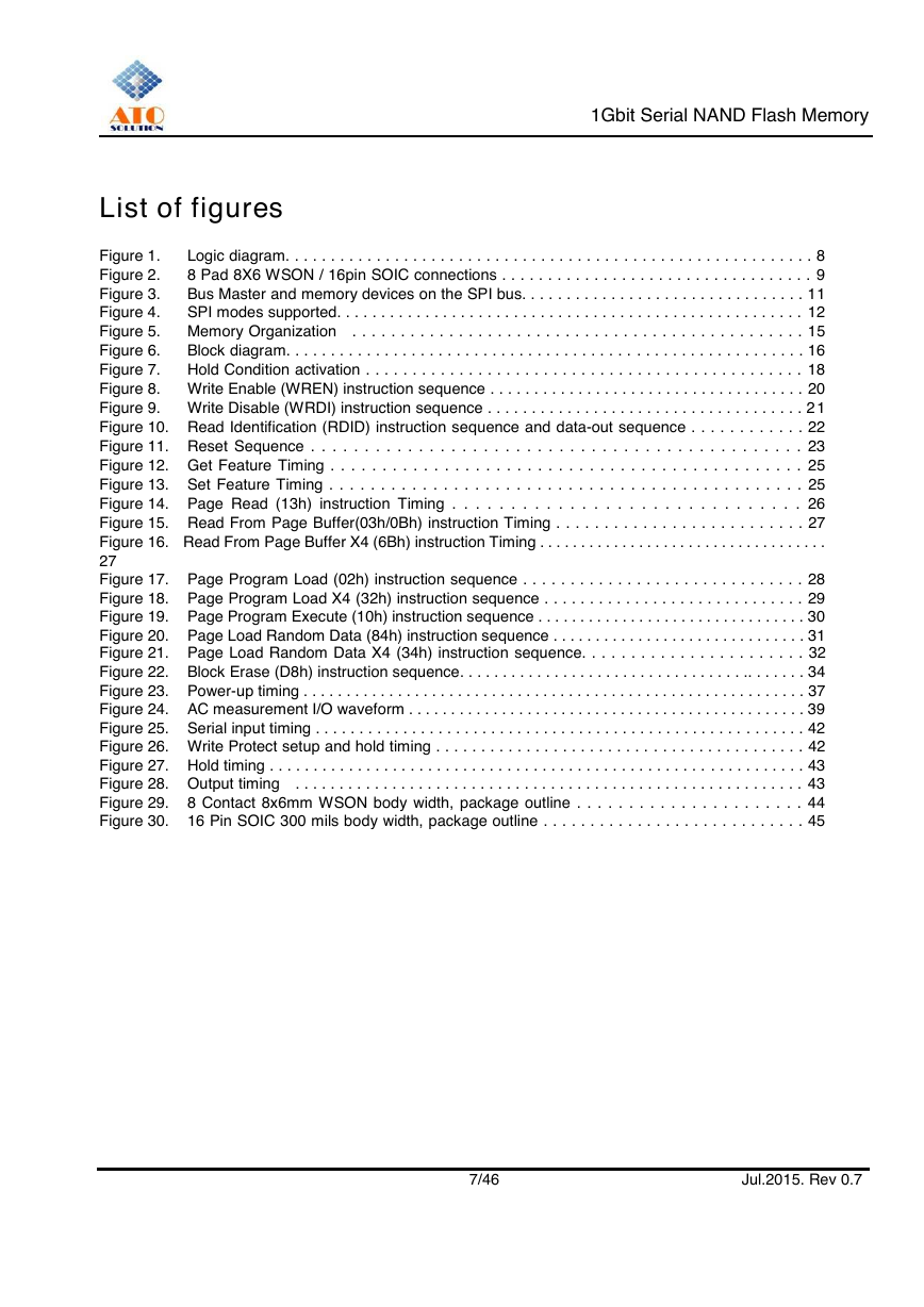
Figure 1. Logic diagram. . . . . . . . . . . . . . . . . . . . . . . . . . . . . . . . . . . . . . . . . . . . . . . . . . . . . . . . . . 8
Figure 2. 8 Pad 8X6 WSON / 16pin SOIC connections . . . . . . . . . . . . . . . . . . . . . . . . . . . . . . . . . . 9
Figure 3. Bus Master and memory devices on the SPI bus. . . . . . . . . . . . . . . . . . . . . . . . . . . . . . . . 11
Figure 4.
SPI modes supported. . . . . . . . . . . . . . . . . . . . . . . . . . . . . . . . . . . . . . . . . . . . . . . . . . . . . 12
Figure 5. Memory Organization . . . . . . . . . . . . . . . . . . . . . . . . . . . . . . . . . . . . . . . . . . . . . . . 15
Figure 6. Block diagram. . . . . . . . . . . . . . . . . . . . . . . . . . . . . . . . . . . . . . . . . . . . . . . . . . . . . . . . . . 16
Figure 7.
Hold Condition activation . . . . . . . . . . . . . . . . . . . . . . . . . . . . . . . . . . . . . . . . . . . . . . . 18
Figure 8. Write Enable (WREN) instruction sequence . . . . . . . . . . . . . . . . . . . . . . . . . . . . . . . . . . . . 20
Figure 9. Write Disable (WRDI) instruction sequence . . . . . . . . . . . . . . . . . . . . . . . . . . . . . . . . . . . . 2 1
Figure 10. Read Identification (RDID) instruction sequence and data-out sequence . . . . . . . . . . . . 22
Figure 11. Reset Sequence . . . . . . . . . . . . . . . . . . . . . . . . . . . . . . . . . . . . . . . . . . . . . . 23
Figure 12. Get Feature Timing . . . . . . . . . . . . . . . . . . . . . . . . . . . . . . . . . . . . . . . . . . . . . . 25
Figure 13. Set Feature Timing . . . . . . . . . . . . . . . . . . . . . . . . . . . . . . . . . . . . . . . . . . . . . . 25
Figure 14. Page Read (13h) instruction Timing . . . . . . . . . . . . . . . . . . . . . . . . . . . . . . 26
Figure 15. Read From Page Buffer(03h/0Bh) instruction Timing . . . . . . . . . . . . . . . . . . . . . . . . . . 27
Figure 16. Read From Page Buffer X4 (6Bh) instruction Timing . . . . . . . . . . . . . . . . . . . . . . . . . . . . . . . . . . .
27
Figure 17. Page Program Load (02h) instruction sequence . . . . . . . . . . . . . . . . . . . . . . . . . . . . . . 28
Figure 18. Page Program Load X4 (32h) instruction sequence . . . . . . . . . . . . . . . . . . . . . . . . . . . . . 29
Figure 19. Page Program Execute (10h) instruction sequence . . . . . . . . . . . . . . . . . . . . . . . . . . . . . . . . 30
Figure 20. Page Load Random Data (84h) instruction sequence . . . . . . . . . . . . . . . . . . . . . . . . . . . . . . 31
Figure 21. Page Load Random Data X4 (34h) instruction sequence. . . . . . . . . . . . . . . . . . . . . . . 32
Figure 22. Block Erase (D8h) instruction sequence. . . . . . . . . . . . . . . . . . . . . . . . . . . . . . . . . .. . . . . . . 34
Figure 23. Power-up timing . . . . . . . . . . . . . . . . . . . . . . . . . . . . . . . . . . . . . . . . . . . . . . . . . . . . . . . . . . . 37
Figure 24. AC measurement I/O waveform . . . . . . . . . . . . . . . . . . . . . . . . . . . . . . . . . . . . . . . . . . . . . . . 39
Figure 25. Serial input timing . . . . . . . . . . . . . . . . . . . . . . . . . . . . . . . . . . . . . . . . . . . . . . . . . . . . . . . . 42
Figure 26. Write Protect setup and hold timing . . . . . . . . . . . . . . . . . . . . . . . . . . . . . . . . . . . . . . . . . 42
Figure 27. Hold timing . . . . . . . . . . . . . . . . . . . . . . . . . . . . . . . . . . . . . . . . . . . . . . . . . . . . . . . . . . . . . 43
Figure 28. Output timing . . . . . . . . . . . . . . . . . . . . . . . . . . . . . . . . . . . . . . . . . . . . . . . . . . . . . . . . . . 43
Figure 29. 8 Contact 8x6mm WSON body width, package outline . . . . . . . . . . . . . . . . . . . . . . 44
Figure 30. 16 Pin SOIC 300 mils body width, package outline . . . . . . . . . . . . . . . . . . . . . . . . . . . . 45
7/46 Jul.2015. Rev 0.7
�
1. General Description
1Gbit Serial NAND Flash Memory
The ATO25D1GA is 1G-bit with spare 32Mbit capacity. The device is offered in 3.3V power
supply. Its NAND cell provides the most cost-effective solution for the solid state mass storage
market. The memory is divided into blocks that can be erased independently so it possible to
preserve valid data while old data is erased. The device contains 1024 blocks, composed by
64 pages consisting in two NAND structures of 32series connected Flash Cells. A program
operation can be performed in typical 200us on the 2048-bytes and an erase operation can be
performed in typical 2ms on a 128K-bytes block. Data in the page can be read out at 25ns
cycle time per byte. The on-chip write control automates all program and erase functions
including pulse repetition, where required, and internal verification and margining of data. Even
the write-intensive systems can take advantage of the ATO25D1GA’s extended reliability of
100K program/erase cycles by providing ECC(Error Correction Code) with real time
mapping-out algorithm.
ATO25D1GA features a serial peripheral interface and software protocol allowing operation
on a simple 3-wire bus while it is in single I/O mode. The three signals are a clock input(SCLK),
a serial data input(SI), and a serial data output(SO). Serial access to the device is enabled by
CS# input. When it is in four I/O read mode, the SI pin, SO pin, WP# pin and HOLD# pin
become SIO0 pin, SIO1 pin, SIO2 pin SIO3 pin for address/dummy bits input and data output.
The copy back function allows the optimization of defective blocks management : when a page
program operation fails the data can be directly programmed in another page inside the same
array section without the time consuming serial data insertion phase. The ATO25D1GA is an
optimum solution for large nonvolatile storage applications such as solid state file storage and
other portable applications requiring non-volatility.
After program/erase command
issued, auto program/erase algorithms which
program/erase and verify the specified page or sector/block locations will be executed. Up to
2Kbytes can be programmed at a time. Pages can be erased in groups of 128KB erase. To
provide user with ease of interface, a status register is included to indicate the status of the
chip. The status read command can be issued to detect completion status of a program or
erase operation via OIP bit. Advanced security features enhance the protection and security
functions, please see security features section for more details.
is
The ATO25D1GA supports JEDEC standard manufacturer and device identification with a
16Kbytes(8 pages) Secured OTP.
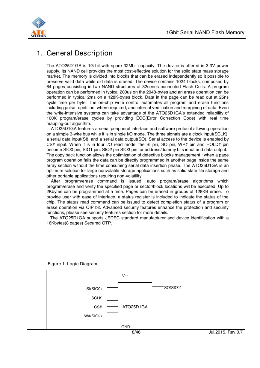
Figure 1. Logic Diagram
VCC
GND
SO(SIO1)
SI(SIO0)
SCLK
CS#
W#(SIO2)
HOLD#(SIO3)
8/46 Jul.2015. Rev 0.7
ATO25D1GA
�


 2023年江西萍乡中考道德与法治真题及答案.doc
 2012年重庆南川中考生物真题及答案.doc
 2013年江西师范大学地理学综合及文艺理论基础考研真题.doc
 2020年四川甘孜小升初语文真题及答案I卷.doc
 2020年注册岩土工程师专业基础考试真题及答案.doc
 2023-2024学年福建省厦门市九年级上学期数学月考试题及答案.doc
 2021-2022学年辽宁省沈阳市大东区九年级上学期语文期末试题及答案.doc
 2022-2023学年北京东城区初三第一学期物理期末试卷及答案.doc
 2018上半年江西教师资格初中地理学科知识与教学能力真题及答案.doc
 2012年河北国家公务员申论考试真题及答案-省级.doc
 2020-2021学年江苏省扬州市江都区邵樊片九年级上学期数学第一次质量检测试题及答案.doc
 2022下半年黑龙江教师资格证中学综合素质真题及答案.doc