Interface for SPECCTRA®
�
Copyrights
Software, documentation and related materials:
Copyright © 2006 Altium Limited
This software product is copyrighted and all rights are reserved. The distribution and sale of this
product are intended for the use of the original purchaser only per the terms of the License Agreement.
This document may not, in whole or part, be copied, photocopied, reproduced, translated, reduced or
transferred to any electronic medium or machine-readable form without prior consent in writing from
Altium Limited.
U.S. Government use, duplication or disclosure is subject to RESTRICTED RIGHTS under applicable
government regulations pertaining to trade secret, commercial computer software developed at private
expense, including FAR 227-14 subparagraph (g)(3)(i), Alternative III and DFAR 252.227-7013
subparagraph (c)(1)(ii).
P-CAD is a registered trademark and P-CAD Schematic, P-CAD Relay, P-CAD PCB, P-CAD ProRoute,
P-CAD QuickRoute, P-CAD InterRoute, P-CAD InterRoute Gold, P-CAD Library Manager, P-CAD
Library Executive, P-CAD Document Toolbox, P-CAD InterPlace, P-CAD Parametric Constraint Solver,
P-CAD Signal Integrity, P-CAD DesignFlow, P-CAD ViewCenter, Master Designer, and Associate
Designer are trademarks of Altium Limited. SPECCTRA in a registered trademark of
Cadence Design Systems, Inc. All other brand names are trademarks of their respective companies.
Altium Limited
www.altium.com
�
P-CAD Interface for SPECCTRA®
This manual explains how to use the P-CAD SPECCTRA�
autorouter (SP6, SP10, SP4, and SP2) interface. These
autorouters work differently than other P-CAD autorouters.
For SPECCTRA, there are no interactive functions as with P-
CAD PRO Route. SPECCTRA is driven by a command file
called a DO file. You set up a DO file using the Route
Autorouters dialog. When you start running SPECCTRA, P-
CAD PCB runs the autorouter as a separate Windows
process.
Saving your Design
You must save your design in P-CAD ASCII format. P-CAD
PCB then translates this format into the native SPECCTRA
format. Upon termination of the autorouter, PCB merges the
original PCB ASCII file with the routes produced by the
autorouter. The resultant file is your routed design.
If you start running SPECCTRA and the design is not
currently in P-CAD ASCII format, you are given the option to
have P-CAD automatically save the design in ASCII format
or abort the routing operation.
P-CAD Interface for SPECCTRA®
1
�
Route Autorouters Dialog
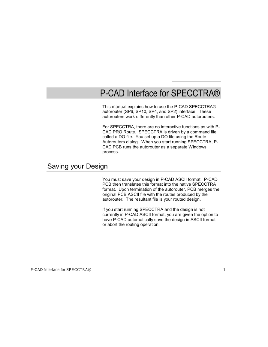
When you select the SPECCTRA autorouter from the
Autorouters combobox, the Route Autorouters dialog
appears as follows:
setting up the SPECCTRA
autorouter
This dialog is designed to simplify creating DO files, building
net classes, and specifying command line options.
SPECCTRA uses a different command file format called a
DO file to define the routing strategy. The Strategy button in
this dialog is replaced with a DO File button.
DO File Button
The DO File is an ASCII file that contains SPECCTRA
commands that execute in sequence to control autorouting.
It includes all data needed by the autorouter to route the
board. The DO filename initially appears as the same name
as the current design file, but with an .DO extension. This is
the default filename.
2 P-CAD Interface for SPECCTRA®
�
Output PCB File Button
The Output PCB File button displays a dialog in which you
can specify the name and location of your output design file
after it has been routed. Here too, a default name has been
provided. The letter R (for routed) precedes the current
design filename. The last character is dropped if the new
name exceeds eight characters. The default file extension is
.PCB.
The default name can be overridden by clicking the Output
PCB File button. The dialog which appears allows you to
specify the name and location of your routed PCB board.
Output Log File Button
In addition to the output file, the SPECCTRA autorouter
generates a report file at the end of the routing session,
detailing the results of the session. The Output Log File
button displays the Select Output Log File dialog, in which
you can specify the name and location of your report file.
Load Button
Select the Load button to restore saved DO files. Choose
the DO filename, then click Load. The DO file is then read
into memory and may be edited as text or through the DO
Wizard.
Save Button
Anytime after you have selected a DO filename, you can
save the file by clicking Save. The DO file is also saved
automatically when you start the route.
Set Base Button
The Set Base button returns the DO and output files to their
default filenames. This is a simple way to go back and start
P-CAD Interface for SPECCTRA® 3
�
over again when assigning filenames. The default names
are derived from the design filename, including the full path.
DO Wizard
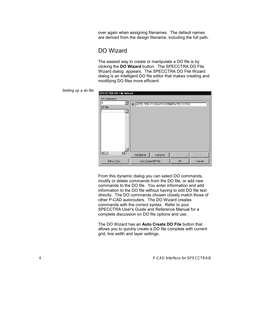
The easiest way to create or manipulate a DO file is by
clicking the DO Wizard button. The SPECCTRA DO File
Wizard dialog appears. The SPECCTRA DO File Wizard
dialog is an intelligent DO file editor that makes creating and
modifying DO files more efficient.
Setting up a do file
From this dynamic dialog you can select DO commands,
modify or delete commands from the DO file, or add new
commands to the DO file. You enter information and add
information to the DO file without having to edit DO file text
directly. The DO commands chosen closely match those of
other P-CAD autorouters. The DO Wizard creates
commands with the correct syntax. Refer to your
SPECCTRA User's Guide and Reference Manual for a
complete discussion on DO file options and use.
The DO Wizard has an Auto Create DO File button that
allows you to quickly create a DO file complete with current
grid, line width and layer settings.
4 P-CAD Interface for SPECCTRA®
�
Edit as Text
You can click the Edit as Text button to bring up the file in a
text editor. The DO file created or modified in this manner is
used verbatim as input to the SPECCTRA autorouter.
Net Classes Button
The option lets you define a group of nets that share
common rules. Collections of nets sharing the same rules
are referred to as a net class.
When you click the Net Classes button, the Net Classes
dialog appears.
Defining net classes
P-CAD Interface for SPECCTRA® 5
�
This class editor allows you to create named net classes
using pre-defined clearance rules or pre-defined SPECCTRA
autorouter clearance rules and then assign nets to that class.
You can also add user-defined attributes to the net classes
for your own use.
PCB Design Rules Checking verifies clearances and the
attributes listed below when they have been defined in the
net class:
� MaxNetLength
� MaxVias
� MinNetLength
� ViaStyle
� Width
For net clearances the rules can be further refined by
specifying clearance rules for pairs of objects, like pad to pad
clearances or line to via clearances.
To create named net classes:
1. Enter a class name in the Classes box.
2. Click Add.
3. To include a net from the Unassigned Nets area to
the new net class you may use any of the following
methods:
� Select a single net and click the Add button.
� Double click on a net to move it from Unassigned
to Nets in this Class and vice versa.
6 P-CAD Interface for SPECCTRA®
�



 2023年江西萍乡中考道德与法治真题及答案.doc
 2012年重庆南川中考生物真题及答案.doc
 2013年江西师范大学地理学综合及文艺理论基础考研真题.doc
 2020年四川甘孜小升初语文真题及答案I卷.doc
 2020年注册岩土工程师专业基础考试真题及答案.doc
 2023-2024学年福建省厦门市九年级上学期数学月考试题及答案.doc
 2021-2022学年辽宁省沈阳市大东区九年级上学期语文期末试题及答案.doc
 2022-2023学年北京东城区初三第一学期物理期末试卷及答案.doc
 2018上半年江西教师资格初中地理学科知识与教学能力真题及答案.doc
 2012年河北国家公务员申论考试真题及答案-省级.doc
 2020-2021学年江苏省扬州市江都区邵樊片九年级上学期数学第一次质量检测试题及答案.doc
 2022下半年黑龙江教师资格证中学综合素质真题及答案.doc