save as: 101-200 Transistor circuits.pdf
Go to: 1 - 100 Transistor Circuits
Go to: 100 IC Circuits
80 CIRCUITS as of 7-3-2011
See TALKING ELECTRONICS WEBSITE
email Colin Mitchell:
talking@tpg.com.au
INTRODUCTION
�
This is the second half of our Transistor Circuits e-book. It contains a further 100
circuits, with many of them containing one or more Integrated Circuits (ICs).
It's amazing what you can do with transistors but when Integrated Circuits came
along, the whole field of electronics exploded.
IC's can handle both analogue as well as digital signals but before their arrival, nearly
all circuits were analogue or very simple "digital" switching circuits.
Let's explain what we mean.
The word analogue is a waveform or signal that is changing (increasing and
decreasing) at a constant or non constant rate. Examples are voice, music, tones,
sounds and frequencies. Equipment such as radios, TV's and amplifiers process
analogue signals.
Then digital came along.
Digital is similar to a switch turning something on and off.
The advantage of digital is two-fold.
Firstly it is a very reliable and accurate way to send a signal. The signal is either HIGH
or LOW (ON or OFF). It cannot be half-on or one quarter off.
And secondly, a circuit that is ON, consumes the least amount of energy in the
controlling device. In other words, a transistor that is fully turned ON and driving a
motor, dissipates the least amount of heat. If it is slightly turned ON or nearly fully
turned ON, it gets very hot.
And obviously a transistor that is not turned on at all will consume no energy.
A transistor that turns ON fully and OFF fully is called a SWITCH.
When two transistors are cross-coupled in the form of a flip flop, any pulses entering
the circuit cause it to flip and flop and the output goes HIGH on every second pulse.
This means the circuit halves the input pulses and is the basis of counting or dividing.
Digital circuits also introduce the concept of two inputs creating a HIGH output when
both are HIGH and variations of this.
This is called "logic" and introduces terms such as "Boolean algebra" and "gates."
Integrated Circuits started with a few transistors in each "chip" and increased to whole
mini or micro computers in a single chip. These chips are called Microcontrollers and a
single chip with a few surrounding components can be programmed to play games,
monitor heart-rate and do all sorts of amazing things. Because they can process
information at high speed, the end result can appear to have intelligence and this is
where we are heading: AI (Artificial Intelligence).
But let's crawl before we walk and come to understand how to interface some of
these chips to external components.
In this Transistor Circuits ebook, we have presented about 100 interesting circuits
using transistors and chips.
In most cases the IC will contain 10 - 100 transistors, cost less than the individual
components and take up much less board-space. They also save a lot of circuit
designing and quite often consume less current than discrete components.
In all, they are a fantastic way to get something working with the least componentry.
A list of of Integrated Circuits (Chips) is provided at the end of this book to help you
identify the pins and show you what is inside the chip.
Some of the circuits are available from Talking Electronics as a kit, but others will
have to be purchased as individual components from your local electronics store.
Electronics is such an enormous field that we cannot provide kits for everything. But if
you have a query about one of the circuits, you can contact me.
Colin Mitchell
TALKING ELECTRONICS.
talking@tpg.com.au
To save space we have not provided lengthy explanations of how the circuits work.
This has already been covered in TALKING ELECTRONICS Basic Electronics Course, and
can be obtained on a CD for $10.00 (posted to anywhere in the world) See Talking
Electronics website for more details: http://www.talkingelectronics.com
MORE INTRO
�
There are two ways to learn electronics.
One is to go to school and study theory for 4 years and come out with all the
theoretical knowledge in the world but almost no practical experience.
We know this type of person. We employed them (for a few weeks!). They think
everything they design WILL WORK because their university professor said so.
The other way is to build circuit after circuit and get things to work. You may not
know the in-depth theory of how it works but trial and error gets you there.
We know. We employed this type of person for up to 12 years.
I am not saying one is better than the other but most electronics enthusiasts are not
"book worms" and anyone can succeed in this field by constantly applying themselves
with "constructing projects." You actually learn 10 times faster by applying yourself
and we have had technicians repairing equipment after only a few weeks on the job.
It would be nothing for an enthusiast to build 30 - 40 circuits from our previous
Transistor eBook and a similar number from this book. Many of the circuits are
completely different to each other and all have a building block or two that you can
learn from.
Electronics enthusiasts have an uncanny understanding of how a circuit works and if
you have this ability, don't let it go to waste.
Electronics will provide you a comfortable living for the rest of your life and I mean
this quite seriously. The market is very narrow but new designs are coming along all
the time and new devices are constantly being invented and more are always needed.
Once you get past this eBook of "Chips and Transistors" you will want to investigate
microcontrollers and this is when your options will explode.
You will be able to carry out tasks you never thought possible, with a chip as small as
8 pins and a few hundred lines of code.
As I say in my speeches. What is the difference between a "transistor man" and a
"programmer?" TWO WEEKS!
In two weeks you can start to understand the programming code for a microcontroller
and perform simple tasks such as flashing a LED and produce sounds and outputs via
the press of a button.
All these things are covered on Talking Electronics website and you don't have to buy
any books or publications. Everything is available on the web and it is instantly
accessible. That's the beauty of the web.
Don't think things are greener on the other side of the fence, by buying a text book.
They aren't. Everything you need is on the web AT NO COST.
The only thing you have to do is build things. If you have any technical problem at all,
simply email Colin Mitchell and any question will be answered. Nothing could be
simpler and this way we guarantee you SUCCESS. Hundreds of readers have already
emailed and after 5 or more emails, their circuit works. That's the way we work. One
thing at a time and eventually the fault is found.
If you think a circuit will work the first time it is turned on, you are fooling yourself.
All circuits need corrections and improvements and that's what makes a good
electronics person. Don't give up. How do you think all the circuits in these eBooks
were designed? Some were copied and some were designed from scratch but all had to
be built and adjusted slightly to make sure they worked perfectly.
I don't care if you use bread-board, copper strips, matrix board or solder the
components in the air as a "bird's nest." You only learn when the circuit gets turned
on and WORKS!
In fact the rougher you build something, the more you will guarantee it will work
when built on a printed circuit board.
However, high-frequency circuits (such as 100MHz FM Bugs) do not like open layouts
and you have to keep the construction as tight as possible to get them to operate
reliably.
In most other cases, the layout is not critical.
TRANSISTORS
Most of the transistors used in our circuits are BC 547 and BC 557. These are classified
as "universal" or "common" NPN and PNP types with a voltage rating of about 25v,
100mA collector current and a gain of about 100. Some magazines use the term "TUP"
(for Transistor Universal PNP) or "TUN" (for Transistor Universal NPN). We simply use
Philips types that everyone recognises. You can use almost any type of transistor to
replace them and here is a list of the equivalents and pinouts:
�
�
CONTENTS red indicates 1-100 Transistor Circuits
Adjustable High Current Power Supply
Aerial Amplifier
Alarm Using 4 buttons
Audio Amplifier (mini)
Battery Monitor MkI
Battery Monitor MkII
Bike Turning Signal
Beacon (Warning Beacon 12v)
Beeper Bug
Blocking Oscillator
Book Light
Buck Regulator 12v to 5v
Camera Activator
Capacitor Discharge Unit MkII (CDU2) Trains
Car Detector (loop Detector)
Car Light Alert
Charger - NiCd
Chip Programmer (PIC) Circuits 1,2 3
Circuit Symbols Complete list of Symbols
Clap Switch
Code Lock
Colour Code for Resistors - all resistors
Constant Current
Crystal Tester
Dark Detector with beep Alarm
Darlington Transistor
Decaying Flasher
Driving a LED
Fading LED
Flasher (simple) 3 more in 1-100 circuits
Flashing Beacon (12v Warning Beacon)
Fluorescent Inverter for 12v supply
FM Transmitters - 11 circuits
Hex Bug
H-Bridge
High Current from old cells
High Current Power Supply
Increasing the output current
Inductively Coupled Power Supply
Intercom
Latching A Push Button
Latching Relay
LED Detects light
LEDs on 240v
LEDs Show Relay State
Limit Switches
Low fuel Indicator
Low Voltage cut-out
Low Voltage Flasher
Mains Detector
Mains Night Light
Make any capacitor value
Make any resistor value
Metal Detector
Model Railway time
NiCd Charger
Phase-Shift Oscillator - good design
Phone Bug
Phone Tape-3
PIC Programmer Circuits 1,2 3
Powering a LED
Power ON
Power Supplies - Fixed
Power Supplies - Adjustable LMxx series
Power Supplies - Adjustable 78xx series
Power Supplies - Adjustable from 0v
Power Supply - Inductively Coupled
PWM Controller
Quiz Timer
Railway time
Random Blinking LEDs
Rectifying a Voltage
Resistor Colour Code
Resistor Colour Code - 4, 5 and 6 Bands
Reversing a Motor & 2 & 3
Sequencer
Shake Tic Tac LED Torch
Simple Flasher
Simple Touch-ON Touch-OFF Switch
Siren
Soft Start power supply
Super-Alpha Pair (Darlington Transistor)
Sziklai transistor
Telephone amplifier
Telephone Bug
Touch-ON Touch-OFF Switch
Tracking Transmitter
Track Polarity - model railway
Train Detectors
Transformerless Power Supply
Vehicle Detector loop Detector
VHF Aerial Amplifier
Voltage Doubler
Voltage Multipliers
Voyager - FM Bug
Wailing Siren
XtalTester
Zapper - 160v
1-watt LED
1.5 watt LED
3-Phase Generator
5v from old cells - circuit 1
5v from old cells - circuit 2
12v Flashing Beacon (Warning Beacon)
20 LEDs on 12v supply
240v Detector
240v - LEDs
�
RESISTOR COLOUR CODE
See resistors from 0.22ohm to 22M in full colour at end of book and another resistor table
RECTIFYING a Voltage
These circuits show how to change an oscillating voltage (commonly called AC) to DC. The term AC means
Alternating Current but it really means Alternating Voltage as the rising and falling voltage produces an increasing and
decreasing current.
The term DC means Direct Current but it actually means Direct or unchanging Voltage.
The output of the following circuits will not be pure DC (like that from a battery) but will contain ripple. Ripple is
reduced by adding a capacitor (electrolytic) to the output.
�
DARK DETECTOR with beep-beep-beep Alarm
This circuit detects darkness and produces a beep-beep-beep alarm. The first two transistors form a high-gain amplifier
with feedback via the 4u7 to produce a low-frequency oscillator. This provides voltage for the second oscillator (across
the 1k resistor) to drive a speaker.
�
3-PHASE SINEWAVE GENERATOR
This circuit produces a sinewave and each phase can be tapped at the point shown.
TRANSFORMERLESS POWER SUPPLY
This clever design uses 4 diodes in a bridge to produce a fixed
voltage power supply capable of supplying 35mA.
All diodes (every type of diode) are zener diodes. They all
break down at a particular voltage. The fact is, a power diode
breaks down at 100v or 400v and its zener characteristic is not
useful.
But if we put 2 zener diodes in a bridge with two ordinary power
diodes, the bridge will break-down at the voltage of the zener.
This is what we have done. If we use 18v zeners, the output will
be 17v4.
When the incoming voltage is positive at the top, the left zener
provides 18v limit (and the left power-diode produces a drop of
0.6v). This allows the right zener to pass current just like a normal diode but the voltage available to it is just 18v. The
output of the right zener is 17v4. The same with the other half-cycle.
The current is limited by the value of the X2 capacitor and this is 7mA for each 100n when in full-wave (as per this
circuit). We have 10 x 100n = 1u capacitance. Theoretically the circuit will supply 70mA but we found it will only deliver
35mA before the output drops. The capacitor should comply with X1 or X2 class. The 10R is a safety-fuse resistor.
The problem with this power supply is the "live" nature of the negative rail. When the power supply is connected as
shown, the negative rail is 0.7v above neutral. If the mains is reversed, the negative rail is 340v (peak) above neutral
and this will kill you as the current will flow through the diode and be lethal. You need to touch the negative rail (or the
positive rail) and any earthed device such as a toaster to get killed. The only solution is the project being powered must
be totally enclosed in a box with no outputs.
LEDs on 240v
I do not like any circuit connected directly to 240v mains. However
Christmas tress lights have been connected directly to the mains for 30
years without any major problems.
Insulation must be provided and the lights (LEDs) must be away from
prying fingers.
Read the article above for the type of capacitor and add an equal number
of LEDs in each string so the reverse voltage is equal across each LED.
It does not matter how many LEDs you add to each string as the
brightness will be the same. As you add each pair, the current will drop a
very small amount until eventually, when you have 100 LEDs in each
string, the current will be zero.
For the circuit shown, each LED will see 20mA peak during the half-cycle
they are illuminated. The 1k resistor will drop 15v - since the RMS current
is 15mA (15mA x 1,000 ohms = 15v). No rectifier diodes are needed.
The LEDs are the "rectifiers." Very clever. You must have LEDs in both
directions to charge and discharge the capacitor. The resistor is provided to take a heavy surge current through one
of the strings of LEDs if the circuit is switched on when the mains is at a peak. A 100n cap will deliver 7mA RMS or
10mA peak in full wave or 3.5mA RMS (5mA peak) in half-wave. The LEDs above detect peak current.
The current-capability of a capacitor needs more explanation. In the diagram on the left we see a capacitor feeding
a full-wave power supply. This is exactly the same as the LEDs on 240v circuit above. Imagine the LOAD resistor is
removed. Two of the diodes will face down and two will face up. This is exactly the same as the LEDs facing up and
facing down in the circuit above. The only difference is the mid-point is joined. Since the voltage on the mid-point of
one string is the same as the voltage at the mid-point of the other string, the link can be removed and the circuit will
operate the same.
�


 Meta大模型论文:The Llama 3 Herd of Models.pdf
 ACS0709(传感器资料).PDF
 495个C语言常见问题集.pdf
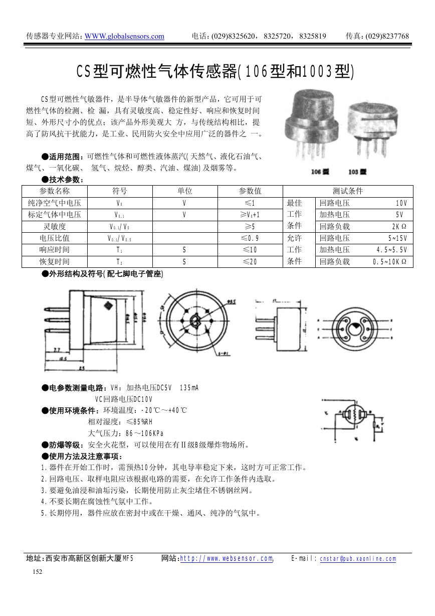 CS型可燃性气体传感器(106型和1003型)(传感器资料).pdf
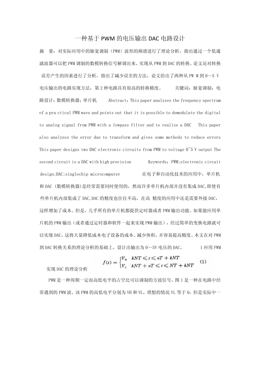 一种基于PWM的电压输出DAC电路设计.pdf
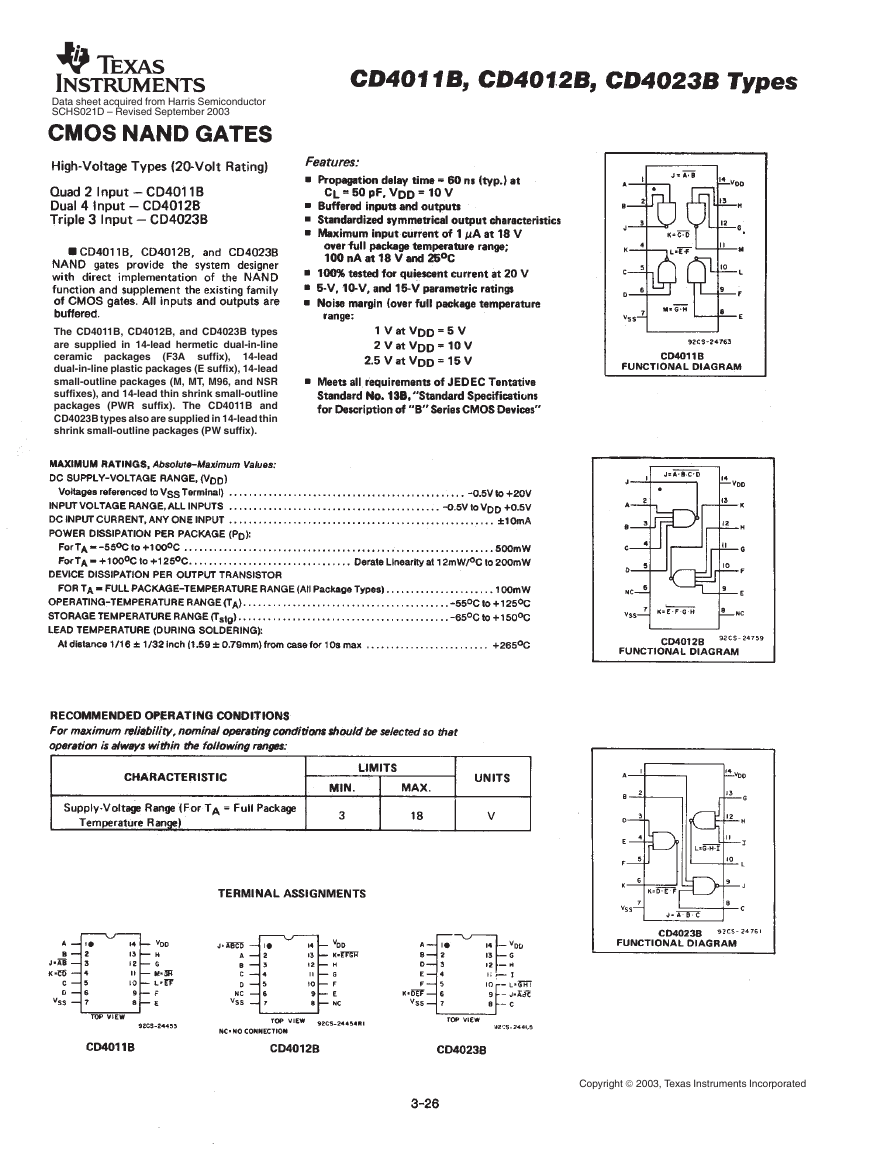 cd4011b(智能车电机驱动).pdf
 电路设计规范_中兴.pdf
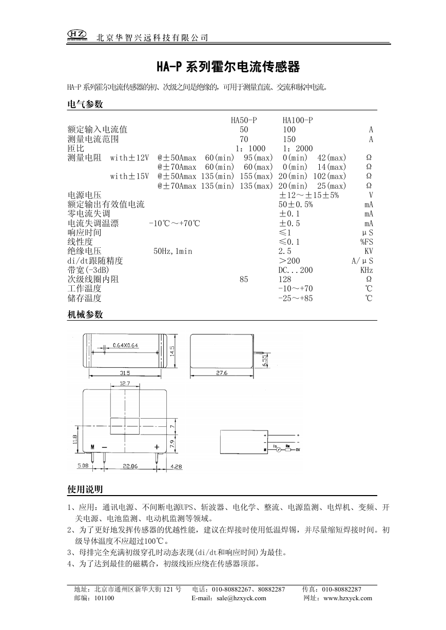 HA50-P(传感器资料).pdf
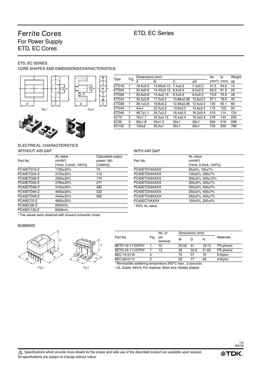 ETD-core(TDK磁芯资料).pdf