CiA DS 150 Version 1.1
CiA DS 205-1 Addendum
CiA DS 205-2 Addendum
CAN power
management layer
specification
© CAN in Automation e. V.
�
Content
CiA DS 150 V1.1: CAN Power Management Layer Specification - Network Standby-/Power
Reduction Capabilities
CiA DS 205-1A: Addendum to CiA DS-205-1 - CAL LMT Service Specification
CiA DS 205-2A: Addendum to CiA DS-205-2 - CAL LMT Protocol Specification
�
General information on licensing and patents
CAN in AUTOMATION (CiA) calls attention to the possibility that some of the elements of this
CiA specification may be subject of patent rights. CiA shall not be responsible for identifying
any or all such patent rights.
Because this specification is licensed free of charge, there is no warranty for this
specification, to the extent permitted by applicable law. Except when otherwise stated in
writing the copyright holder and/or other parties provide this specification “as is” without
warranty of any kind, either expressed or implied, including, but not limited to, the implied
warranties of merchantability and fitness for a particular purpose. The entire risk as to the
correctness and completeness of the specification is with you. Should this specification prove
failures, you assume the cost of all necessary servicing, repair or correction.
© CiA 2008
All rights reserved. Unless otherwise specified, no part of this publication may be reproduced or
utilized in any form or by any means, electronic or mechanical, including photocopying and microfilm,
without permission in writing from CiA at the address below.
CAN in Automation e. V.
Kontumazgarten 3
DE - 90429 Nuremberg, Germany
Tel.: +49-911-928819-0
Fax: +49-911-928819-79
Url: www.can-cia.org
Email: headquarters@can-cia.org
�
CAN Power Management Layer Specification
Network Standby-/Power Reduction Capabilities
CiA Draft Standard 150
Version 1.1
May 1997
' CAN in Automation (CiA) e. V.
�
CiA DS-150
1. Scope
CAN Power Management Layer Specification
May 1997
This document specifies facilities and services of an Power Management Layer protocol entity
on the CAN bus allowing significant reduction of power consumption in CAN networks by
the introduction of the so-called network standby capability. The power reduction facilities of
current CAN controller hardware designs by using the sleep mode, which can be recognized as
a de-facto standard; are supported for usage under all higher layer protocols during an internal
Power Management Layer IDLE state.
Although all hardware CAN controller devices on the market offer power reduction
mechanisms implemented in a similar way (de-facto standard), this feature is not covered by
/1/. The corresponding services will be introduced in chapter 3.1 and summarized in chapter 4.
for further reference.
The purpose of an ISO/OSI Power Management Layer specification is to build up reliable
communication, what is trivial in CAN networks where CAN controllers may not enter the
sleep mode. If one or more CAN controllers in a network are switched to the sleep mode, this
might result in message loss. The described protocol solves this problem by managing the
network-wide consistency of the CAN-controllers operation modes in an intelligent manner.
The multi-master architecture of the network is thereby fully maintained.
WARNING: This CAN Power Management Layer deals with reliable communication on
CAN networks with power reduction capability. There is very little relationship to the
ISO/OSI Power Management Layer otherwise.
The main features of the CAN Power Management Layer are
• standby capability supports CAN sleep mode for usage under all CAN higher-layer
protocols, i.e. functional LLC interface remains virtually the same although time behaviour
may change
• full compatibility with CAN multi-master decentralized network architecture
• easy hardware implementation/integration into CAN peripherial controllers
• coexistance of nodes with and without Power Management Layer support is possible
(performance may suffer but can be optimized, see interoperability rules in chapter 5.5)
- 2 -
�
2. References
/1/ ISO 11898, "Road vehicles - Interchange of digital Information - Controller Area Network
(CAN) for high-speed communications". November 1993.
/2/
ISO 7498, "OSI Basic Reference Model".
/3/ CiA DS-201 "CAN in OSI Reference Model". Version 1.1. February 1996.
/4/ CiA DS-205-1A "Addendum to CiA/DS-205-1 CAL LMT Service Specification". May
1997.
/5/ CiA DS-205-2A "Addendum to CiA/DS-205-2 CAL LMT Protocol Specification. May
1997
3. General Description
3.1 CAN ISO/OSI Layer-2 Hardware Power Reduction Capabilities
Within a CAN network, consisting of several nodes, power reduction can be achieved during
idle-times without bus traffic by switching the nodes’ local CAN controller device into a
special mode, the sleep mode. In combination with the sleep mode, additional local power
reduction mechanisms may be used, which allow a considerable saving of power. Lowest
power consumption can be achieved in CMOS-designs, if the nodes processor is stopped.
The CAN standard /1/ specifies that the CAN data link layers (layer-2) subentity LLC
(Logical Link Control) owns a Node_Status and informs higher layer entities via this status,
whether the Fault Confinement Logic has entered the bus-off state. For all existing CAN
controllers, this Node_Status is extended by the above-mentioned sleep mode for power
reduction purposes. Therefore, all existing CAN peripherial controllers feature an additional
LLC-ªPower Reduction Capability, which is outside the scope of /1/.
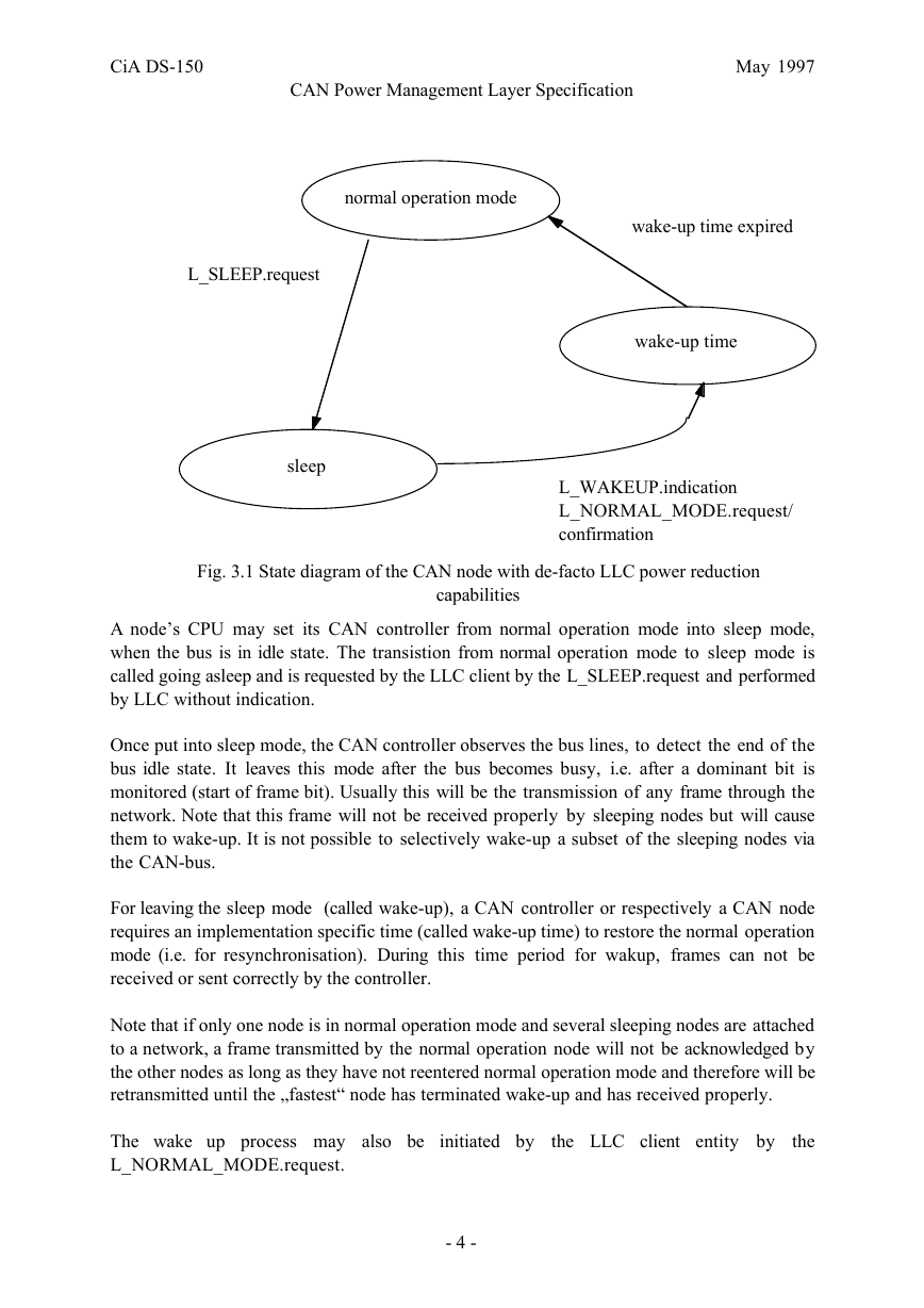
CAN controllers with LLC power reduction capability behave as follows (see extended LLC
power reduction capability state diagram in Fig.3.1):
' CAN in Automation (CiA) e. V.
�
CiA DS-150
May 1997
CAN Power Management Layer Specification
normal operation mode
wake-up time expired
L_SLEEP.request
sleep
wake-up time
L_WAKEUP.indication
L_NORMAL_MODE.request/
confirmation
Fig. 3.1 State diagram of the CAN node with de-facto LLC power reduction
capabilities
A nodes CPU may set its CAN controller from normal operation mode into sleep mode,
when the bus is in idle state. The transistion from normal operation mode to sleep mode is
called going asleep and is requested by the LLC client by the L_SLEEP.request and performed
by LLC without indication.
Once put into sleep mode, the CAN controller observes the bus lines, to detect the end of the
bus idle state. It leaves this mode after the bus becomes busy, i.e. after a dominant bit is
monitored (start of frame bit). Usually this will be the transmission of any frame through the
network. Note that this frame will not be received properly by sleeping nodes but will cause
them to wake-up. It is not possible to selectively wake-up a subset of the sleeping nodes via
the CAN-bus.
For leaving the sleep mode (called wake-up), a CAN controller or respectively a CAN node
requires an implementation specific time (called wake-up time) to restore the normal operation
mode (i.e. for resynchronisation). During this time period for wakup, frames can not be
received or sent correctly by the controller.
Note that if only one node is in normal operation mode and several sleeping nodes are attached
to a network, a frame transmitted by the normal operation node will not be acknowledged by
the other nodes as long as they have not reentered normal operation mode and therefore will be
retransmitted until the ªfastest node has terminated wake-up and has received properly.
The wake up process may also be
L_NORMAL_MODE.request.
initiated by
the LLC client entity by
the
- 4 -
�
CiA DS-150
May 1997
CAN Power Management Layer Specification
As the CAN subsystem behaves different in sleep mode (no proper immediate receiption),
higher layer protocols usually dont refer to it and expect the LLC remaining in normal
operation mode.
3.2 Power Management Layer Conception
The current CiA DS-201 specification "CAN in OSI Reference Model" /3/ defines a three
layered architecture for open CAN bus systems. This model defines a trivial functionality for
the Power Management Layer, i.e. the functionality of the Data Link Layer is referenced and
offered to the higher layers directly.
In order to take advantage of the power reduction capabilities, the Power Management Layer
standby capability introduces a state machine with an IDLE state (in which switching the
CAN controller to the sleep mode is allowed) and in which the loss of the first incoming CAN
frame and a delay to restore normal operation mode is foreseen by the communication partner.
When a frame should be sent from a standby-capable node to another one and the nodes are in
IDLE state, this frame has to be preceded by two frames, with the purpose to wake up the
CAN controllers (wakeup-unqualified) and to repeat this wakeup (wakeup-qualified). Two
frames are necessary to distinguish this wakeup from possible noise or unqualified disturbance
by non-standby-capable nodes. Between the unqualified and the qualified wake-up-service an
appropriate wake-up time delay will allow resynchronisation of the sleeping CAN controllers.
All nodes with Power Management Layer standby capability enter the IDLE state
synchronously. For this purpose, all nodes in the network are equipped with a special
Window Timer which is reset after reception or transmission of any valid CAN frame over the
bus. Until a special Minimum Active Time expires, setting the CAN controller into sleep
mode is not allowed. No wakeup CAN frame is required within the Minimum Active Time
period to continue the communication; the protocol overhead is kept at a minimum.
NOTE:
For the implementation of the CAN Power Management Layer, the nodes CAN peripherial
controller must be able to detect all CAN frames on the bus (although the content of the
frames are not relevant for the SLSU). Usually this can be performed only if message filtering
is dissabled and all L_DATA.indications, L_REMOTE_indications and all L_DATA and
L_REMOTE.confirms are notified to the Power Management Layer Service Unit SLSU.
Due to deviations in the node’s timebases and to the possible coexistance of non-standby
capable nodes (no Power Management Layer, immediate transmission of frames), the
implementation of the mechanism is more complicated than described here. More details can
be found in chapter 5.
The mechanism is completely independent from the client i.e. higher layer instance, which is
requesting the transmission of a particular frame. Therefore, a convenient solution for the
implementation of the above mentioned mechanism is to specify a Power Management Layer,
which encapsulates and translates all the service calls to the data link layer entity. Thus all
higher layer service specifications remain unaffected. Now any higher layer instance sends its
- 5 -
�
