CAN Physical Layer for Industrial Applications
CiA
CAN in AUTOMATION
CiA Draft Standard 102 Version 2.0
CAN Physical Layer for Industrial Applications
20 April 1994
Two-Wire Differential Transmission
Scope
1.
The scope of this document is, to define the content of the physical layer and the basic characteristics
of the physical medium, for communication according to the Controller Area Network protocol
specification (CAN) between different types of electronic modules in general industrial applications.
CAN is a serial communication protocol supporting distributed real-time control and multiplexing.
This part refers to using a differentially driven two-wire bus line with common return as physical
medium.
2. References
/1/
/2/
/3/
/4/
/5/
3. Definitions
See /3/.
4. Basic Concepts of CAN
See /3/.
Controller Area Network protocol specification, Version 2.0
Robert Bosch GmbH 1991
ISO 7498: 1984, Information processing systems - Open systems interconnection -
Basic reference model
ISO 11898: 1992, Road vehicles - Interchange of digital information -
Controller area network (CAN) for high-speed communication
D-Sub connector specification (DIN 41652 or corresponding international standard)
CAN in Automation, Working Group Physical Layer,
Protocol of the 2nd Meeting on 16.Jun.1992
CiA DS 102 Version 2.0
�
Layered Architecture of CAN
5.
See /2/, /3/.
2
© CiA 2008 - All rights reserved
�
6. Description of the Medium Access Unit
6.1 Physical Medium Attachment Sublayer Specification (Transceiver)
See /3/. The maximum rating for VCAN_H and VCAN_L is +16V.
Galvanic isolation between the bus nodes is optional.
6.2 Medium Dependent Interface Specification (Bus connector)
6.2.1 Electrical Parameters
See /3/.
The output voltage at pin 9 (external positive supply) shall be +7 V < V+ < +13 V at an output current
of up to 100 mA (current consumption of module). Modules are not allowed to source current into this
pin.
Note: The electrical parameters for pin 9 (V+) refer to the proposal of the working group "Physical
Layer". They are not yet agreed upon by the General Assembly of CAN in Automation.
6.2.2 Mechanical Parameters
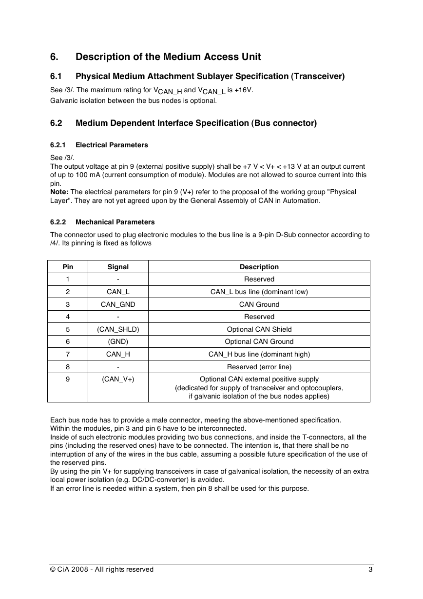
The connector used to plug electronic modules to the bus line is a 9-pin D-Sub connector according to
/4/. Its pinning is fixed as follows
Pin
1
2
3
4
5
6
7
8
9
Signal
-
CAN_L
CAN_GND
-
(CAN_SHLD)
(GND)
CAN_H
-
(CAN_V+)
Description
Reserved
CAN_L bus line (dominant low)
CAN Ground
Reserved
Optional CAN Shield
Optional CAN Ground
CAN_H bus line (dominant high)
Reserved (error line)
Optional CAN external positive supply
(dedicated for supply of transceiver and optocouplers,
if galvanic isolation of the bus nodes applies)
Each bus node has to provide a male connector, meeting the above-mentioned specification.
Within the modules, pin 3 and pin 6 have to be interconnected.
Inside of such electronic modules providing two bus connections, and inside the T-connectors, all the
pins (including the reserved ones) have to be connected. The intention is, that there shall be no
interruption of any of the wires in the bus cable, assuming a possible future specification of the use of
the reserved pins.
By using the pin V+ for supplying transceivers in case of galvanical isolation, the necessity of an extra
local power isolation (e.g. DC/DC-converter) is avoided.
If an error line is needed within a system, then pin 8 shall be used for this purpose.
© CiA 2008 - All rights reserved
3
�
6.3 Physical Medium Specification (Bus line)
The physical medium is a two-wire bus line with common return being terminated at both ends by
resistors representing the characteristic impedance of the line. Its maximum length is 1 km. It is
allowed to use bridge-devices or repeaters to increase the number of bus nodes which may be
connected, or to increase the allowed distance between the bus nodes (to e.g. more than 1 km), or to
provide galvanic isolation (a bridge-device contains at least two CAN-controllers and two transceivers).
The bus wires may be routed parallel, twisted and/or shielded, depending on EMC requirements. The
wiring topology should be as close as possible to a single line structure, in order to minimize
reflections. The cable stubs for connection of the bus nodes should be as short as possible, especially
at high bit rates. At 1Mbit/s, the length of the cable stubs should not exceed 0.3 m (see /3/).
The ground inputs of all transceivers are interconnected. The parameters
• Specific resistance per length unit
•
Length
• Current
Location of the power supply input
•
should be chosen in a way, that the difference between the ground potentials of the transceivers does
not exceed 2V. If necessary, galvanic isolation has to be applied, to reduce the current through the
ground line. In general, it is advantageous to locate the power supply input in the center of the bus
line.
Implementation Concepts
6.3.1 Electrical Specification
See /3/. At bus line length greater than 40 m, the specific resistance of the bus cable should be lower
than the value given in /3/. The recommendations included in /5/ should be taken into account.
6.3.2
There are two basic concepts how to implement the bus line.
6.3.2.1 Interconnected Bus Line Sections
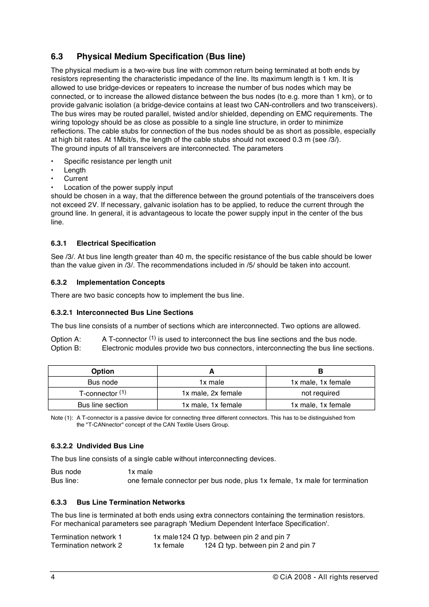
The bus line consists of a number of sections which are interconnected. Two options are allowed.
A T-connector (1) is used to interconnect the bus line sections and the bus node.
Option A:
Option B:
Electronic modules provide two bus connectors, interconnecting the bus line sections.
Option
Bus node
T-connector (1)
Bus line section
A
1x male
1x male, 2x female
1x male, 1x female
B
1x male, 1x female
not required
1x male, 1x female
Note (1): A T-connector is a passive device for connecting three different connectors. This has to be distinguished from
the "T-CANnector" concept of the CAN Textile Users Group.
6.3.2.2 Undivided Bus Line
The bus line consists of a single cable without interconnecting devices.
Bus node
Bus line:
1x male
one female connector per bus node, plus 1x female, 1x male for termination
6.3.3 Bus Line Termination Networks
The bus line is terminated at both ends using extra connectors containing the termination resistors.
For mechanical parameters see paragraph 'Medium Dependent Interface Specification'.
Termination network 1
Termination network 2
1x male 124 Ω typ. between pin 2 and pin 7
1x female
124 Ω typ. between pin 2 and pin 7
4
© CiA 2008 - All rights reserved
�
6.4 Bit Rates
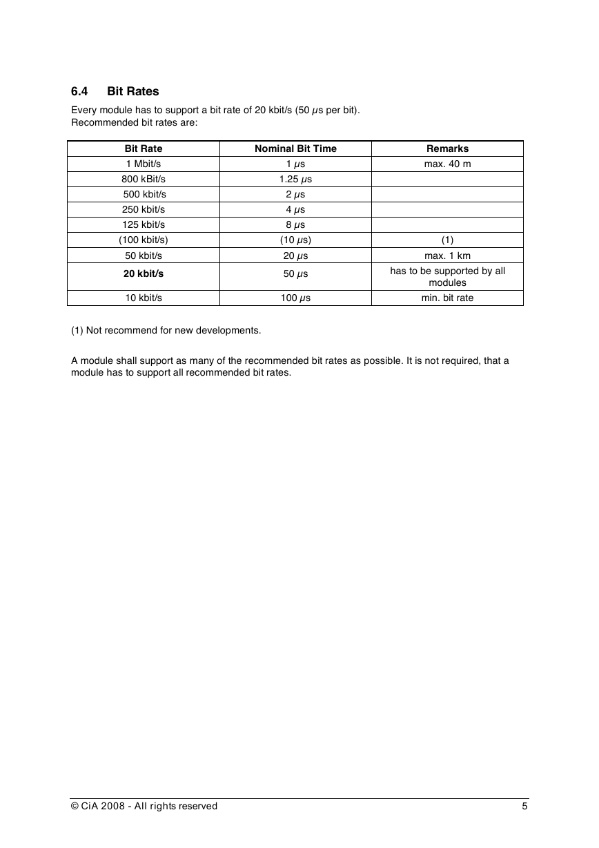
Every module has to support a bit rate of 20 kbit/s (50 µs per bit).
Recommended bit rates are:
Nominal Bit Time
Bit Rate
1 Mbit/s
800 kBit/s
500 kbit/s
250 kbit/s
125 kbit/s
(100 kbit/s)
50 kbit/s
20 kbit/s
10 kbit/s
1 µs
1.25 µs
2 µs
4 µs
8 µs
(10 µs)
20 µs
50 µs
100 µs
Remarks
max. 40 m
(1)
has to be supported by all
max. 1 km
modules
min. bit rate
(1) Not recommend for new developments.
A module shall support as many of the recommended bit rates as possible. It is not required, that a
module has to support all recommended bit rates.
© CiA 2008 - All rights reserved
5
�
General information on licensing and patents
CAN in AUTOMATION (CiA) calls attention to the possibility that some of the elements of this CiA specification
may be subject of patent rights. CiA shall not be responsible for identifying any or all such patent rights.
Because this specification is licensed free of charge, there is no warranty for this specification, to the
extent permitted by applicable law. Except when otherwise stated in writing the copyright holder and/or
other parties provide this specification “as is” without warranty of any kind, either expressed or implied,
including, but not limited to, the implied warranties of merchantability and fitness for a particular
purpose. The entire risk as to the correctness and completeness of the specification is with you.
Should this specification prove failures, you assume the cost of all necessary servicing, repair or
correction.
© CiA 2008
All rights reserved. Unless otherwise specified, no part of this publication may be reproduced or
utilized in any form or by any means, electronic or mechanical, including photocopying and microfilm,
without permission in writing from CiA at the address below.
CAN in Automation e. V.
Kontumazgarten 3
DE - 90429 Nuremberg, Germany
Tel.: +49-911-928819-0
Fax: +49-911-928819-79
Url: www.can-cia.org
Email: headquarters@can-cia.org
6
© CiA 2008 - All rights reserved
�

