Application Note AN048
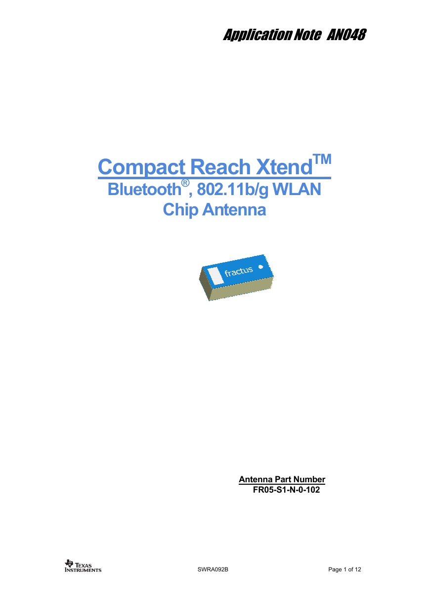
Compact Reach XtendTM
Bluetooth®, 802.11b/g WLAN
Chip Antenna
Antenna Part Number
FR05-S1-N-0-102
SWRA092B
Page 1 of 12
�
Application Note AN048
Table of Contents
NOTES ............................................................................................................................ 3
1
ANTENNA DESCRIPTION ............................................................................................. 4
2
QUICK REFERENCE GUIDE*.................................................................................................. 4
3
ANTENNA PERFORMANCE ......................................................................................... 5
VSWR & RADIATION EFFICIENCY ............................................................................... 5
RADIATION PATTERN.................................................................................................. 6
GAIN ......................................................................................................................... 7
MECHANICAL CHARACTERISTICS ............................................................................ 8
PCB FOOTPRINT DETAILS .......................................................................................... 8
DIMENSIONS AND TOLERANCES .................................................................................. 9
ASSEMBLY PROCESS ................................................................................................. 9
PACKAGING ............................................................................................................. 11
GENERAL INFORMATION .......................................................................................... 12
DOCUMENT HISTORY................................................................................................ 12
3.1
3.2
3.3
4.1
4.2
4.3
4.4
5.1
4
5
SWRA092B
Page 2 of 12
�
Application Note AN048
1
Notes
• The antenna product described in this document is protected by at least one of the
following Patents and Patent Applications owned by Fractus: WO0154225,
WO0122528, PCT/EP01/10589, PCT/EP02/07837, US60/613394, US60/627653 and
PCT/EP02/07836.
• The configuration recommended in this document for the Compact Reach XtendTM chip
antenna can be applied to the following proprietary and ZigBeeTM ready transceivers
and
CC2400/2420/2430/CC2431/2500/CC2510/CC2511/CC2550/
transmitters:
CC2520/CCZACC06.
• All information contained within this document is property of Fractus and is subject to
change without prior notice. Information is provided “as is” and without warranties. It is
prohibited to copy or reproduce this information without prior approval.
SWRA092B
Page 3 of 12
�
Application Note AN048
Antenna Description
2
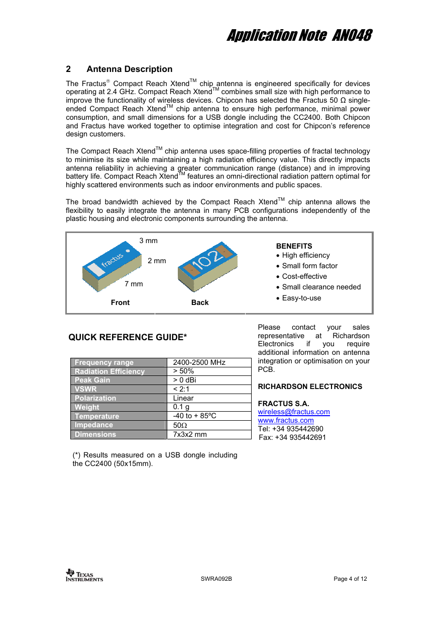
The Fractus® Compact Reach XtendTM chip antenna is engineered specifically for devices
operating at 2.4 GHz. Compact Reach XtendTM combines small size with high performance to
improve the functionality of wireless devices. Chipcon has selected the Fractus 50 Ω single-
ended Compact Reach XtendTM chip antenna to ensure high performance, minimal power
consumption, and small dimensions for a USB dongle including the CC2400. Both Chipcon
and Fractus have worked together to optimise integration and cost for Chipcon’s reference
design customers.
The Compact Reach XtendTM chip antenna uses space-filling properties of fractal technology
to minimise its size while maintaining a high radiation efficiency value. This directly impacts
antenna reliability in achieving a greater communication range (distance) and in improving
battery life. Compact Reach XtendTM features an omni-directional radiation pattern optimal for
highly scattered environments such as indoor environments and public spaces.
The broad bandwidth achieved by the Compact Reach XtendTM chip antenna allows the
flexibility to easily integrate the antenna in many PCB configurations independently of the
plastic housing and electronic components surrounding the antenna.
3 mm
2 mm
7 mm
Front
Back
BENEFITS
• High efficiency
• Small form factor
• Cost-effective
• Small clearance needed
• Easy-to-use
if
you
your
contact
sales
Please
at Richardson
representative
Electronics
require
additional information on antenna
integration or optimisation on your
PCB.
RICHARDSON ELECTRONICS
FRACTUS S.A.
wireless@fractus.com
www.fractus.com
Tel: +34 935442690
Fax: +34 935442691
QUICK REFERENCE GUIDE*
Frequency range
Radiation Efficiency
Peak Gain
VSWR
Polarization
Weight
Temperature
Impedance
Dimensions
2400-2500 MHz
> 50%
> 0 dBi
< 2:1
Linear
0.1 g
-40 to + 85ºC
50Ω
7x3x2 mm
(*) Results measured on a USB dongle including
the CC2400 (50x15mm).
SWRA092B
Page 4 of 12
�
Application Note AN048
Antenna Performance
3
This section provides integration and mounting recommendations for the use of the Compact
Reach XtendTM Chip Antenna within the CC2400 USB dongle. Compact Reach XtendTM has
been designed to purposely minimise product integration efforts and optimise device
performance.
This Application Note provide you with both the performance of the USB dongle with standard
plastic housing and the PCB details necessary to implement the antenna on a client’s board.
3.1 VSWR & Radiation Efficiency
R
R
W
W
S
S
V
V
5
5
4.5
4.5
4
4
3.5
3.5
3
3
2.5
2.5
2
2
1.5
1.5
1
1
2
2
With housing
With housing
With housing
Without housing
Without housing
Without housing
2.1
2.1
2.2
2.2
2.3
2.3
2.4
2.4
2.5
2.5
2.6
2.6
2.7
2.7
2.8
2.8
2.9
2.9
3
3
Frequency [GHz]
Frequency [GHz]
a)
With housing
With housing
Without housing
Without housing
100
100
90
90
80
80
70
70
60
60
50
50
40
40
30
30
20
20
10
10
)
)
%
%
(
(
y
y
c
c
n
n
e
e
i
i
c
c
i
i
f
f
f
f
E
E
0
0
2
2
2.1
2.1
2.2
2.2
2.3
2.3
2.4
2.6
2.4
2.6
Frequency (GHz)
Frequency (GHz)
2.5
2.5
2.7
2.7
2.8
2.8
2.9
2.9
3
3
b)
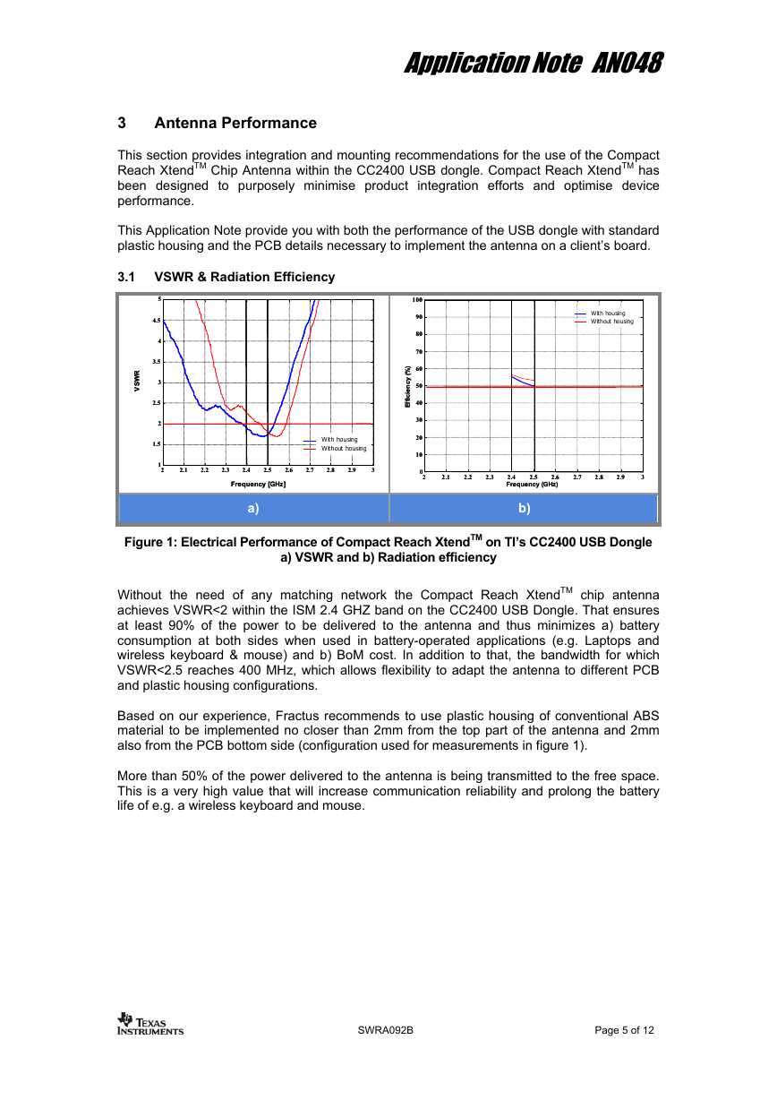
Figure 1: Electrical Performance of Compact Reach XtendTM on TI’s CC2400 USB Dongle
a) VSWR and b) Radiation efficiency
Without the need of any matching network the Compact Reach XtendTM chip antenna
achieves VSWR<2 within the ISM 2.4 GHZ band on the CC2400 USB Dongle. That ensures
at least 90% of the power to be delivered to the antenna and thus minimizes a) battery
consumption at both sides when used in battery-operated applications (e.g. Laptops and
wireless keyboard & mouse) and b) BoM cost. In addition to that, the bandwidth for which
VSWR<2.5 reaches 400 MHz, which allows flexibility to adapt the antenna to different PCB
and plastic housing configurations.
Based on our experience, Fractus recommends to use plastic housing of conventional ABS
material to be implemented no closer than 2mm from the top part of the antenna and 2mm
also from the PCB bottom side (configuration used for measurements in figure 1).
More than 50% of the power delivered to the antenna is being transmitted to the free space.
This is a very high value that will increase communication reliability and prolong the battery
life of e.g. a wireless keyboard and mouse.
SWRA092B
Page 5 of 12
�
Application Note AN048
3.2 Radiation Pattern
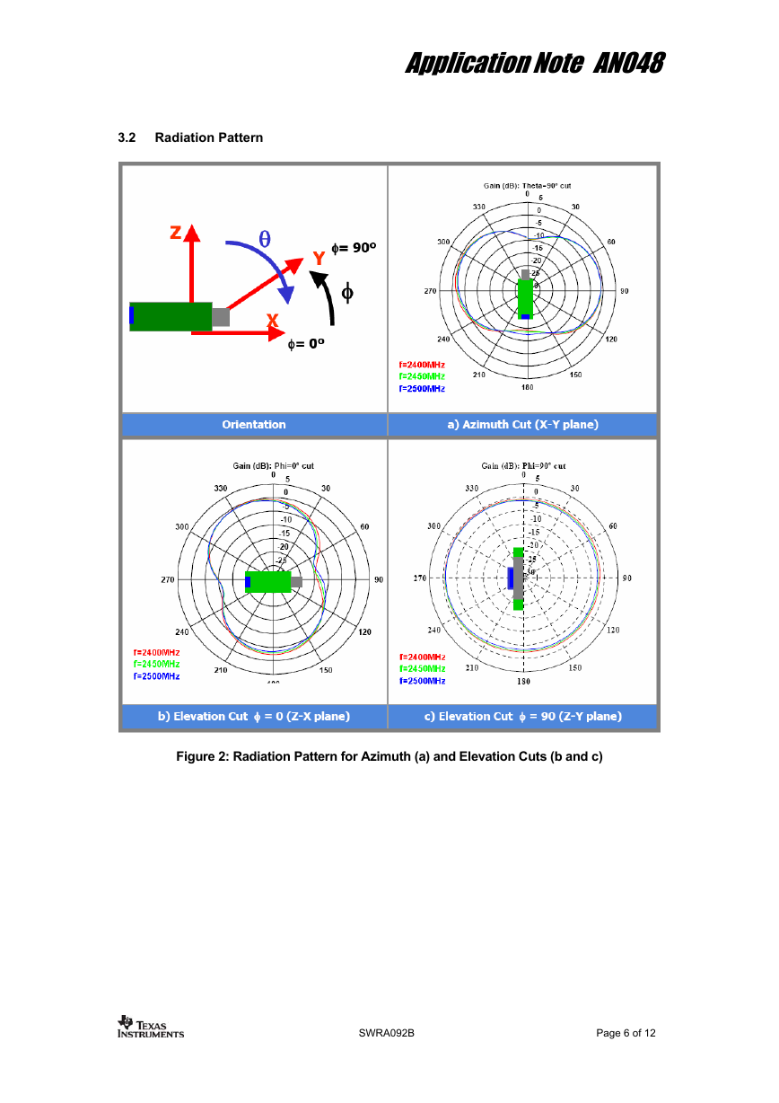
Figure 2: Radiation Pattern for Azimuth (a) and Elevation Cuts (b and c)
SWRA092B
Page 6 of 12
�
Application Note AN048
3.3 Gain
In conventional configurations, a USB device
will typically be connected to a PC standing on
the right side of user’s feet (below table). In
such case, both a wireless keyboard and
mouse will be located at Theta=0º and Phi
ranging from –45º to +45º.
The Compact Reach XtendTM chip antenna
used in the CC2400 USB Dongle achieves very
high gain values (green circle on left side
picture) [0dBi, -0,5 dBi], which will increase link
reliability and maximise data transfer success.
Phi (φ)
Figure 3: Gain [dBi] Projected in 2D Plot from a 3D Measurement
SWRA092B
Page 7 of 12
�
Application Note AN048
4 Mechanical Characteristics
4.1 PCB Footprint Details
All dimensions
listed in millimetres.
Letter
A
B
C
D
E
F
G
H
I
J
K
Meas.
7.00
3.00
1.50
0.20
2.60
3.60
2.00
0.50
3.75
1.50
15.00
Zone occupied by the antenna
Soldering pads, feed point and feeding line
PCB border (no ground-plane)
PCB ground-plane
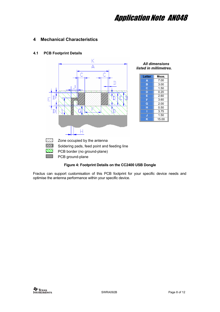
Figure 4: Footprint Details on the CC2400 USB Dongle
Fractus can support customisation of this PCB footprint for your specific device needs and
optimise the antenna performance within your specific device.
SWRA092B
Page 8 of 12
�
