l
e
t
a
r
e
e
c
c
a
,
e
t
a
c
n
u
m
m
o
c
,
e
t
a
c
o
i
l
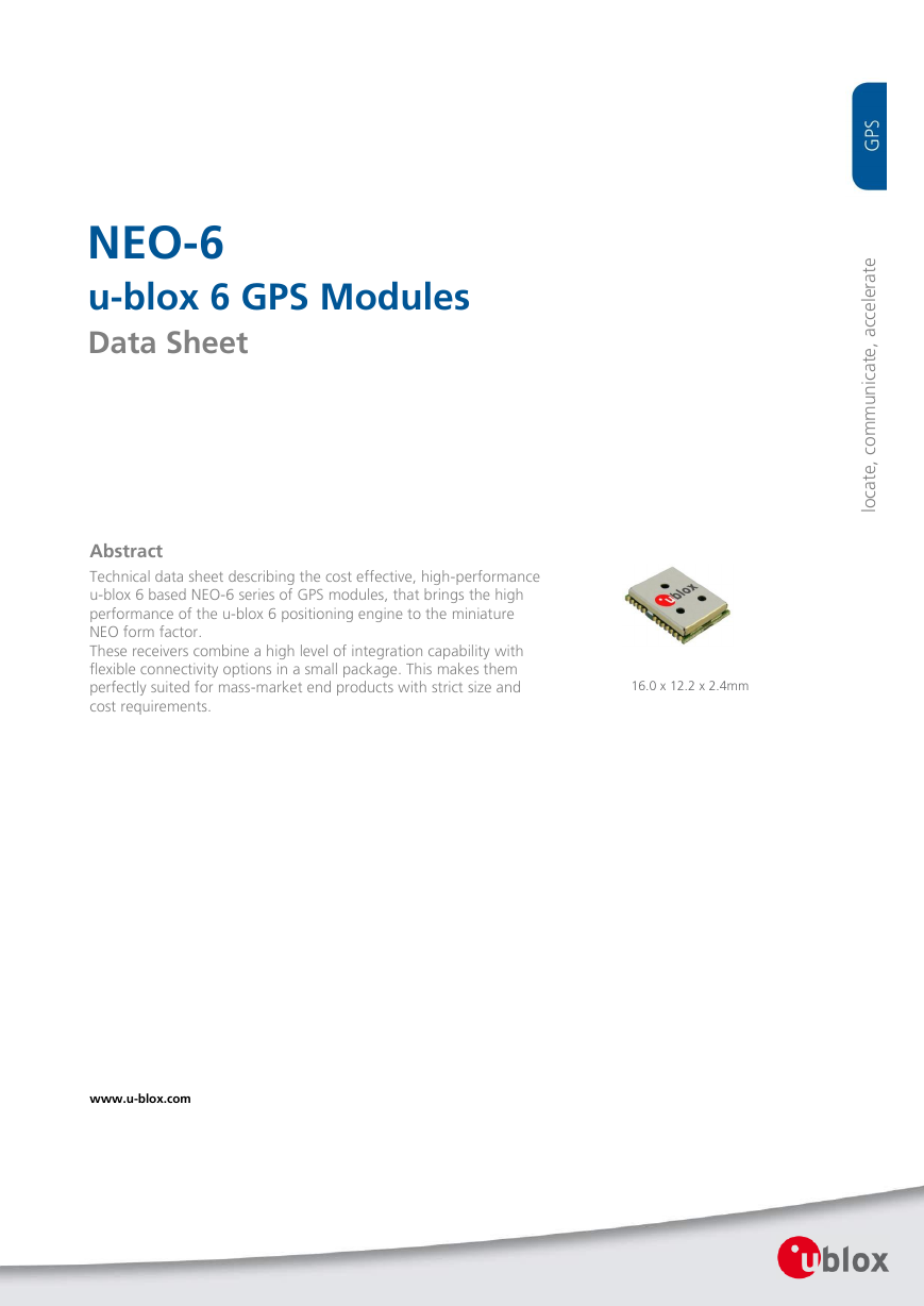
16.0 x 12.2 x 2.4mm
NEO-6
u-blox 6 GPS Modules
Data Sheet
Abstract
Technical data sheet describing the cost effective, high-performance
u-blox 6 based NEO-6 series of GPS modules, that brings the high
performance of the u-blox 6 positioning engine to the miniature
NEO form factor.
These receivers combine a high level of integration capability with
flexible connectivity options in a small package. This makes them
perfectly suited for mass-market end products with strict size and
cost requirements.
www.u-blox.com
�
NEO-6 - Data Sheet
Document Information
Title
Subtitle
NEO-6
u-blox 6 GPS Modules
Document type
Data Sheet
Document number
GPS.G6-HW-09005-C
Document status
Preliminary
Document status information
Objective
Specification
This document contains target values. Revised and supplementary data will be published
later.
Advance
Information
Preliminary
This document contains data based on early testing. Revised and supplementary data will
be published later.
This document contains data from product verification. Revised and supplementary data
may be published later.
Released
This document contains the final product specification.
This document applies to the following products:
Name
NEO-6G
NEO-6Q
NEO-6M
Type number
ROM/FLASH version
NEO-6G-0-001
NEO-6Q-0-001
NEO-6M-0-001
ROM7.03
ROM7.03
ROM7.03
PCN reference
UBX-TM-11049
UBX-TM-11049
UBX-TM-11049
This document and the use of any information contained therein, is subject to the acceptance of the u-blox terms and conditions. They
can be downloaded from www.u-blox.com.
u-blox makes no warranties based on the accuracy or completeness of the contents of this document and reserves the right to make
changes to specifications and product descriptions at any time without notice. Reproduction, use or disclosure to third parties without
express permission is strictly prohibited. Copyright © 2011, u-blox AG.
u-blox® is a registered trademark of u-blox Holding AG in the EU and other countries. ARM® is the registered trademark of ARM Limited in
the EU and other countries.
GPS.G6-HW-09005-C
Page 2 of 27
�
NEO-6 - Data Sheet
Contents
Contents .............................................................................................................................. 3
1 Functional description .................................................................................................. 5
1.1 Overview .............................................................................................................................................. 5
1.2
Product features ................................................................................................................................... 5
1.3 GPS performance .................................................................................................................................. 6
Block diagram ....................................................................................................................................... 7
1.4
Assisted GPS (A-GPS) ............................................................................................................................ 7
1.5
1.6
AssistNow™ Autonomous .................................................................................................................... 7
1.7 Oscillators ............................................................................................................................................. 7
Protocols and interfaces ........................................................................................................................ 8
1.8
UART ............................................................................................................................................. 8
USB ............................................................................................................................................... 8
Serial Peripheral Interface (SPI) ....................................................................................................... 8
Display Data Channel (DDC) .......................................................................................................... 8
Antenna ............................................................................................................................................... 9
Power Management ......................................................................................................................... 9
1.10.1 Maximum Performance Mode ....................................................................................................... 9
1.10.2 Eco Mode ...................................................................................................................................... 9
1.10.3 Power Save Mode ......................................................................................................................... 9
Configuration ................................................................................................................................... 9
1.11.1 Boot-time configuration ................................................................................................................ 9
Design-in ........................................................................................................................................ 10
1.8.1
1.8.2
1.8.3
1.8.4
1.9
1.10
1.11
1.12
2 Pin Definition .............................................................................................................. 11
Pin assignment ................................................................................................................................... 11
2.1
3 Electrical specifications .............................................................................................. 13
3.1
Absolute maximum ratings ................................................................................................................. 13
3.2 Operating conditions .......................................................................................................................... 14
Indicative power requirements ............................................................................................................ 15
3.3
SPI timing diagrams ............................................................................................................................ 16
3.4
Timing recommendations ............................................................................................................ 16
3.4.1
4 Mechanical specifications .......................................................................................... 17
5 Qualification and certification ................................................................................... 18
Reliability tests .................................................................................................................................... 18
Approvals ........................................................................................................................................... 19
5.1
5.2
6 Product handling & soldering .................................................................................... 19
Packaging ........................................................................................................................................... 19
6.1
GPS.G6-HW-09005-C
Preliminary
Page 3 of 27
�
NEO-6 - Data Sheet
6.2
6.1.1
6.1.2
Reels ........................................................................................................................................... 19
Tapes .......................................................................................................................................... 20
Shipment, storage and handling ......................................................................................................... 20
6.2.1 Moisture Sensitivity Levels ........................................................................................................... 20
Shipment ..................................................................................................................................... 20
6.2.2
6.2.3
Storage and floor life ................................................................................................................... 22
Drying ......................................................................................................................................... 22
6.2.4
Reflow soldering ......................................................................................................................... 22
6.2.5
6.2.6
ESD handling precautions ............................................................................................................ 23
7 Default settings .......................................................................................................... 24
8 Labeling and ordering information ........................................................................... 25
Product labeling .................................................................................................................................. 25
8.1
8.2
Explanation of codes........................................................................................................................... 25
8.3 Ordering information .......................................................................................................................... 25
Related documents........................................................................................................... 26
Revision history ................................................................................................................ 26
Contact .............................................................................................................................. 27
GPS.G6-HW-09005-C
Preliminary
Page 4 of 27
�
NEO-6 - Data Sheet
1 Functional description
1.1 Overview
The NEO-6 module series is a family of stand-alone GPS receivers featuring the high performance u-blox 6
positioning engine. These flexible and cost effective receivers offer numerous connectivity options in a miniature
16 x 12.2 x 2.4 mm package. Their compact architecture and power and memory options make NEO-6 modules
ideal for battery operated mobile devices with very strict cost and space constraints.
The 50-channel u-blox 6 positioning engine boasts a Time-To-First-Fix (TTFF) of under 1 second. The dedicated
acquisition engine, with 2 million correlators, is capable of massive parallel time/frequency space searches,
enabling it to find satellites instantly. Innovative design and technology suppresses jamming sources and
mitigates multipath effects, giving NEO-6 GPS receivers excellent navigation performance even in the most
challenging environments.
1.2 Product features
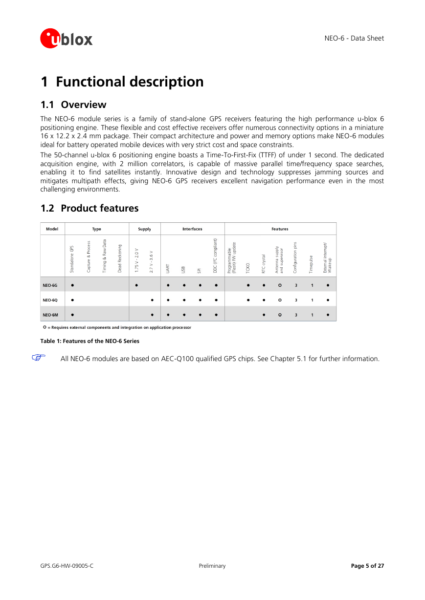
Table 1: Features of the NEO-6 Series
All NEO-6 modules are based on AEC-Q100 qualified GPS chips. See Chapter 5.1 for further information.
GPS.G6-HW-09005-C
Preliminary
Page 5 of 27
�
NEO-6 - Data Sheet
1.3 GPS performance
Parameter
Receiver type
1
Time-To-First-Fix
3
Sensitivity
Specification
50 Channels
GPS L1 frequency, C/A Code
SBAS: WAAS, EGNOS, MSAS
Cold Start (Autonomous)
Warm Start (Autonomous)
Hot Start (Autonomous)
2
Aided Starts
Tracking & Navigation
Reacquisition4
Cold Start (Autonomous)
Maximum Navigation update rate
Horizontal position accuracy5
Configurable Timepulse frequency range
Velocity accuracy
Heading accuracy
Operational Limits
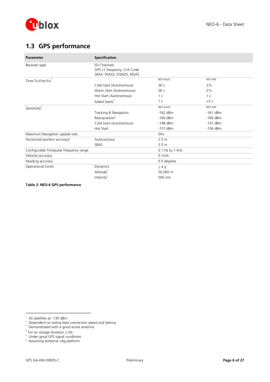
Table 2: NEO-6 GPS performance
Hot Start
Autonomous
SBAS
Dynamics
Altitude6
Velocity6
NEO-6M
27s
27s
1 s
<3 s
NEO-6M
-161 dBm
-160 dBm
-147 dBm
-156 dBm
NEO-6G/Q
26 s
26 s
1 s
1 s
NEO-6G/Q
-162 dBm
-160 dBm
-148 dBm
-157 dBm
5Hz
2.5 m
2.0 m
0.1 Hz to 1 kHz
0.1m/s
0.5 degrees
4 g
50,000 m
500 m/s
1 All satellites at -130 dBm
2 Dependent on aiding data connection speed and latency
3 Demonstrated with a good active antenna
4 For an outage duration 10s
5 Under good GPS signal conditions
6 Assuming Airborne <4g platform
GPS.G6-HW-09005-C
Preliminary
Page 6 of 27
�
1.4 Block diagram
NEO-6 - Data Sheet
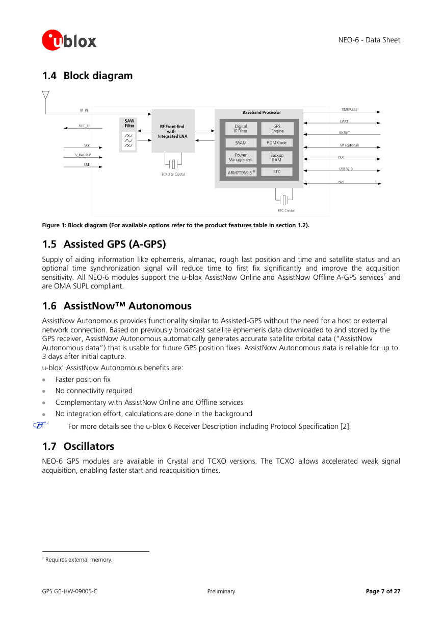
Figure 1: Block diagram (For available options refer to the product features table in section 1.2).
1.5 Assisted GPS (A-GPS)
Supply of aiding information like ephemeris, almanac, rough last position and time and satellite status and an
optional time synchronization signal will reduce time to first fix significantly and improve the acquisition
sensitivity. All NEO-6 modules support the u-blox AssistNow Online and AssistNow Offline A-GPS services7 and
are OMA SUPL compliant.
1.6 AssistNow™ Autonomous
AssistNow Autonomous provides functionality similar to Assisted-GPS without the need for a host or external
network connection. Based on previously broadcast satellite ephemeris data downloaded to and stored by the
GPS receiver, AssistNow Autonomous automatically generates accurate satellite orbital data (“AssistNow
Autonomous data”) that is usable for future GPS position fixes. AssistNow Autonomous data is reliable for up to
3 days after initial capture.
u-blox’ AssistNow Autonomous benefits are:
Faster position fix
No connectivity required
Complementary with AssistNow Online and Offline services
No integration effort, calculations are done in the background
For more details see the u-blox 6 Receiver Description including Protocol Specification [2].
1.7 Oscillators
NEO-6 GPS modules are available in Crystal and TCXO versions. The TCXO allows accelerated weak signal
acquisition, enabling faster start and reacquisition times.
7 Requires external memory.
GPS.G6-HW-09005-C
Preliminary
Page 7 of 27
�
NEO-6 - Data Sheet
1.8 Protocols and interfaces
Protocol
NMEA
UBX
RTCM
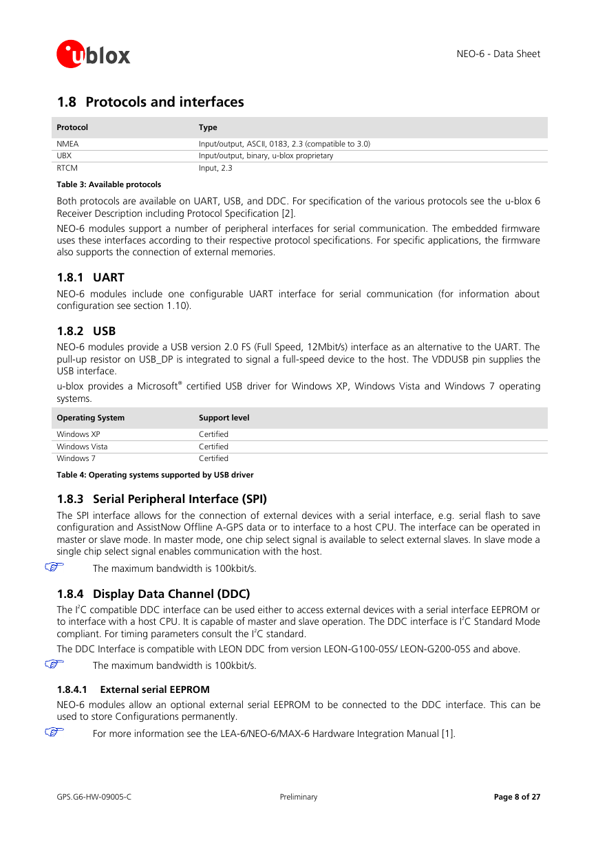
Table 3: Available protocols
Type
Input/output, ASCII, 0183, 2.3 (compatible to 3.0)
Input/output, binary, u-blox proprietary
Input, 2.3
Both protocols are available on UART, USB, and DDC. For specification of the various protocols see the u-blox 6
Receiver Description including Protocol Specification [2].
NEO-6 modules support a number of peripheral interfaces for serial communication. The embedded firmware
uses these interfaces according to their respective protocol specifications. For specific applications, the firmware
also supports the connection of external memories.
1.8.1 UART
NEO-6 modules include one configurable UART interface for serial communication (for information about
configuration see section 1.10).
1.8.2 USB
NEO-6 modules provide a USB version 2.0 FS (Full Speed, 12Mbit/s) interface as an alternative to the UART. The
pull-up resistor on USB_DP is integrated to signal a full-speed device to the host. The VDDUSB pin supplies the
USB interface.
u-blox provides a Microsoft® certified USB driver for Windows XP, Windows Vista and Windows 7 operating
systems.
Operating System
Support level
Windows XP
Windows Vista
Windows 7
Certified
Certified
Certified
Table 4: Operating systems supported by USB driver
1.8.3 Serial Peripheral Interface (SPI)
The SPI interface allows for the connection of external devices with a serial interface, e.g. serial flash to save
configuration and AssistNow Offline A-GPS data or to interface to a host CPU. The interface can be operated in
master or slave mode. In master mode, one chip select signal is available to select external slaves. In slave mode a
single chip select signal enables communication with the host.
The maximum bandwidth is 100kbit/s.
1.8.4 Display Data Channel (DDC)
The I2C compatible DDC interface can be used either to access external devices with a serial interface EEPROM or
to interface with a host CPU. It is capable of master and slave operation. The DDC interface is I2C Standard Mode
compliant. For timing parameters consult the I2C standard.
The DDC Interface is compatible with LEON DDC from version LEON-G100-05S/ LEON-G200-05S and above.
The maximum bandwidth is 100kbit/s.
1.8.4.1 External serial EEPROM
NEO-6 modules allow an optional external serial EEPROM to be connected to the DDC interface. This can be
used to store Configurations permanently.
For more information see the LEA-6/NEO-6/MAX-6 Hardware Integration Manual [1].
GPS.G6-HW-09005-C
Preliminary
Page 8 of 27
�
