CiA Draft Standard 405
CANopen
Interface and Device Profile for
IEC 61131-3 Programmable Devices
Version 2.0
Date: 21.05.2002
© CAN in Automation e. V.
�
�
CiA DS 405
Interface and Device Profile for IEC 61131-3 Programmable Devices
CiA e.V.
Changes
Document Version 1.0 released
Document Version 2.0 released
• editorial changes
• adaptation to Version 4.01 of CiA DS-301
• adaptation to Version 3.0 of CiA DSP-302
•
• Tool Integration redefined
•
Document as Draft Standard Version 2.0 released
function blocks for SDO with arbitrary length
clarifications
HISTORY
Date
March 1998
December 2000
May 2002
General information on licensing and patents
CAN in AUTOMATION (CiA) calls attention to the possibility that some of the elements of this CiA
specification may be subject of patent rights. CiA shall not be responsible for identifying any or all
such patent rights.
Because this specification is licensed free of charge, there is no warranty for this specifica-
tion, to the extent permitted by applicable law. Except when otherwise stated in writing the
copyright holder and/or other parties provide this specification “as is” without warranty of
any kind, either expressed or implied, including, but not limited to, the implied warranties of
merchantability and fitness for a particular purpose. The entire risk as to the correctness
and completeness of the specification is with you. Should this specification prove failures,
you assume the cost of all necessary servicing, repair or correction.
© CiA 2008
All rights reserved. Unless otherwise specified, no part of this publication may be reproduced or
utilized in any form or by any means, electronic or mechanical, including photocopying and micro-
film, without permission in writing from CiA at the address below.
CAN in Automation e. V.
Kontumazgarten 3
DE - 90429 Nuremberg, Germany
Tel.: +49-911-928819-0
Fax: +49-911-928819-79
Url: www.can-cia.org
Email: headquarters@can-cia.org
© CiA 2008 - All rights reserved
i
�
CiA DS 405
Interface and Device Profile for IEC 61131-3 Programmable Devices
CiA e.V.
TABLE OF CONTENTS
1 SCOPE
2 REFERENCES
3 TERMS AND DEFINITIONS
3.1 DATA TYPES
VARIABLES
3.2
3.3
PROGRAM ORGANIZATION UNITS (POU)
3.4 CONFIGURATION ELEMENTS
3.5
3.6 CANOPEN PROFILE-SPECIFIC DEFINITIONS
ACCESS TO NETWORK VARIABLES DEFINITION
4 DATA TYPES
4.1 DATA TYPE CONVERSION FUNCTIONS
4.2 DATA TYPE REPRESENTATION ISSUES
5 ACCESSING CANOPEN FROM WITHIN IEC 61131-3
5.1
VARIABLE BASED ACCESS
Definition of the data direction
Object dictionary entries for IEC 61131-3 variables
Variable names
5.2
FUNCTION BLOCK BASED ACCESS
General function block design issues
Data types
SDO access
Other function blocks
6 TOOL INTEGRATION
BASIC CONCEPT
6.1
6.2 NODE LIST
6.3
ACCESS HANDLER
7 UTILITY FUNCTIONS
1
2
2
2
3
3
4
4
4
5
6
7
8
8
8
9
10
11
12
12
14
17
20
20
20
21
22
22
22
22
22
23
24
25
27
27
28
28
29
31
31
31
32
33
33
35
35
35
35
36
5.1.1
5.1.2
5.1.3
5.2.1
5.2.2
5.2.3
5.2.4
7.1.1
7.2.1
7.2.2
7.2.3
7.2.4
7.2.5
7.2.6
8.4.1
8.4.2
8.4.3
8.4.4
8.6.1
8.6.2
8.6.3
ii
7.1 REMOTE FUNCTIONS BETWEEN RESOURCES
Down-/Upload
7.2 OBJECT DICTIONARY ENTRIES
Project name
Configuration
Resources
Task
Start/Stop (Program/Task)
Debugging/Monitoring
8 APPENDIX (INFORMATIVE)
8.1 DETAILED DESCRIPTION OF NETWORK VARIABLE SEGMENTS
8.2
8.3
8.4
IEC 61131-3 OBJECT DICTIONARY OVERVIEW
EXAMPLE DCF FILE
APPLICATION NOTES
8.5
8.6
IEC 61131-3 SAMPLE CODE
IMPLEMENTATION MODELS FOR IEC 61131-3 DATA TYPE SUPPORT
Network variables
Data type representation issues
EDS
Tool integration
Native support
Padding to next best match
Using arrays or struct
© CiA 2008 - All rights reserved
�
CiA DS 405
Interface and Device Profile for IEC 61131-3 Programmable Devices
CiA e.V.
FIGURES
Figure 1: Interfaces ................................................................................................................................1
Figure 2: IEC 61131-3 software organisation.......................................................................................3
Figure 3: Direction of Network Variables ..............................................................................................8
Figure 4: Type CIA405_DEVICE.........................................................................................................12
Figure 5: Type CIA405_SDO_ERROR...............................................................................................12
Figure 6: Type CIA405_EMCY_ERROR ............................................................................................12
Figure 7: Type CIA405_STATE ..........................................................................................................13
Figure 8: Type CIA405_TRANSITION_STATE .................................................................................13
Figure 9: Type CIA405_CANOPEN_KERNEL_ERROR...................................................................13
Figure 10: Function block CIA405_SDO_WRITE4 ............................................................................14
Figure 11: CIA405_SDO_WRITE4 typical timing diagram................................................................14
Figure 12: Function block CIA405_SDO_WRITE ..............................................................................15
Figure 13: Function block CIA405_SDO_READ4..............................................................................16
Figure 14: CIA405_SDO_READ4 typical timing diagram .................................................................16
Figure 15: Function block CIA405_SDO_READ................................................................................17
Figure 16: Function block CIA405_ GET_LOCAL_NODE_ID ..........................................................17
Figure 17: Function block CIA405_ GET_STATE .............................................................................18
Figure 18: Function block CIA405_ GET_CANOPEN_KERNEL_STATE .......................................18
Figure 19: Function block CIA405_ NMT ...........................................................................................18
Figure 20: Function block CIA405_RECV_EMCY_DEV ...................................................................19
Figure 21: Function block CIA405_RECV_EMCY .............................................................................19
Figure 22: Correlation between programming and network configuration .......................................20
Figure 23: Project structure .................................................................................................................22
Figure 24: Data representation with PDO on CANopen non-compliant PLCs.................................32
Figure 25: Data representation with SDO on CANopen non-compliant and compliant PLCs ........32
Figure 26: Information exchange via DCF..........................................................................................33
Figure 27: Data exchange using converter module...........................................................................33
Figure 28: Compatibility for NVX format .............................................................................................34
TABLES
Table 1: Data types ................................................................................................................................5
Table 2: Data types not transferable via PDO......................................................................................6
Table 3: Data type conversion functions ..............................................................................................6
Table 4: Input network variables ...........................................................................................................9
Table 5: Output network variables ......................................................................................................10
Table 6: New data types ......................................................................................................................11
Table 7: Function blocks......................................................................................................................11
Table 8: Error codes for type CIA405_CANOPEN_KERNEL_ERROR ...........................................14
Table 9: Entries in Nodelist file............................................................................................................21
Table 10: List of object dictionary entries ...........................................................................................30
© CiA 2008 - All rights reserved
iii
�
�
CiA DS 405
Interface and Device Profile for IEC 61131-3 Programmable Devices
CiA e.V.
1 Scope
This document represents the standardised CANopen Interface and Device Profile for IEC 61131-3
programmable devices like PLCs.
All the above devices use communication techniques which conform to those described in the CiA
Draft Standard DS-301 (Application Layer and Communication Profile) and Draft Standard Pro-
posal DSP-302. These documents should be consulted in parallel to this profile.
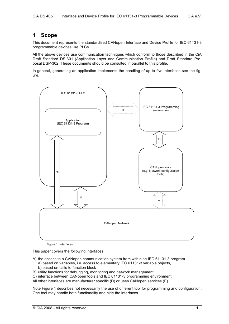
In general, generating an application implements the handling of up to five interfaces see the fig-
ure.
IEC 61131-3 PLC
Application
(IEC 61131-3 Program)
D
IEC 61131-3 Programming
environment
C
CANopen tools
(e.g. Network configuration
tools)
B
E
CANopen Network
A
Figure 1: Interfaces
This paper covers the following interfaces
A) the access to a CANopen communication system from within an IEC 61131-3 program
a) based on variables, i.e. access to elementary IEC 61131-3 variable objects,
b) based on calls to function block
B) utility functions for debugging, monitoring and network management
C) interface between CANopen tools and IEC 61131-3 programming environment
All other interfaces are manufacturer specific (D) or uses CANopen services (E).
Note Figure 1 describes not necessarily the use of different tool for programming and configuration.
One tool may handle both functionality and hide the interfaces.
© CiA 2008 - All rights reserved
1
�
CiA DS 405
Interface and Device Profile for IEC 61131-3 Programmable Devices
CiA e.V.
2 References
/IEC 61131/
IEC 61131 First edition 1993-03
Programmable controllers
- Part 1: general information
- Part 3: programming languages
- Part 5: messaging services
Application Layer and Communication Profile
CiA Draft Standard 301 Version 4.01, 2000-06
Framework for programmable CANopen devices
CiA Draft Standard Proposal 302 Version 3.0, 2000-06
Layer Setting Services and Protocols
CiA Draft Standard Proposal 305 Version 1.1, 2002-02
Electronic Data Sheet Specification for CANopen
CiA Draft Standard Proposal 306 Version 1.1, 2001-06
/DS-301/
/DSP-302/
/DSP-305/
/DSP-306/
3 Terms and definitions
3.1 Data types
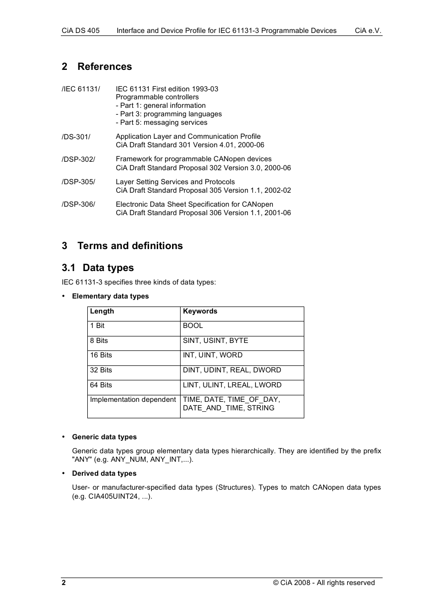
IEC 61131-3 specifies three kinds of data types:
• Elementary data types
Length
1 Bit
8 Bits
16 Bits
32 Bits
64 Bits
Keywords
BOOL
SINT, USINT, BYTE
INT, UINT, WORD
DINT, UDINT, REAL, DWORD
LINT, ULINT, LREAL, LWORD
Implementation dependent TIME, DATE, TIME_OF_DAY,
DATE_AND_TIME, STRING
• Generic data types
Generic data types group elementary data types hierarchically. They are identified by the prefix
"ANY" (e.g. ANY_NUM, ANY_INT,...).
• Derived data types
User- or manufacturer-specified data types (Structures). Types to match CANopen data types
(e.g. CIA405UINT24, ...).
2
© CiA 2008 - All rights reserved
�
