CiA Application Note 808
CANopen
CiA 444 application note and
implementation guideline
Version: 1.0
09 February 2007
CAN in Automation (CiA) e. V.
�
CiA 444 application note and implementation guideline
HISTORY
Date
2007-02-09
Changes
Publication as application note version 1.0
General information on licensing and patents
CAN in AUTOMATION (CiA) calls attention to the possibility that some of the elements of this
CiA specification may be subject of patent rights. CiA shall not be responsible for identifying
any or all such patent rights.
Because this specification is licensed free of charge, there is no warranty for this
specification, to the extent permitted by applicable law. Except when otherwise stated in
writing the copyright holder and/or other parties provide this specification “as is” without
warranty of any kind, either expressed or implied, including, but not limited to, the implied
warranties of merchantability and fitness for a particular purpose. The entire risk as to the
correctness and completeness of the specification is with you. Should this specification prove
failures, you assume the cost of all necessary servicing, repair or correction.
© CiA 2008
All rights reserved. Unless otherwise specified, no part of this publication may be reproduced or
utilized in any form or by any means, electronic or mechanical, including photocopying and microfilm,
without permission in writing from CiA at the address below.
CAN in Automation e. V.
Kontumazgarten 3
DE - 90429 Nuremberg, Germany
Tel.: +49-911-928819-0
Fax: +49-911-928819-79
Url: www.can-cia.org
Email: headquarters@can-cia.org
2
CiA 2008 – All rights reserved
�
CiA 444 application note and implementation guideline
CONTENTS
1 Scope ............................................................................................................................... 4
2 Normative references........................................................................................................ 4
3 Definitions......................................................................................................................... 4
4 General introduction.......................................................................................................... 4
5 CAN connection between a new crane and a new spreader .............................................. 5
6 CAN or direct-wired connection between an old crane and a new spreader....................... 5
7 CAN or direct-wired connection between a new crane and an old spreader....................... 6
8 Direct-wired connection between an old crane and an old spreader .................................. 6
8.1 General ................................................................................................................... 6
8.2 Hardware compatibility ............................................................................................ 7
8.3 Manufacturer-specific transmission with a boosted CANopen network ..................... 7
CiA 2008 – All rights reserved
3
�
CiA 444 application note and implementation guideline
1 Scope
This application note describes the recommended practice and gives application hints for
implementing the connection of crane and spreader.
2 Normative references
/ISO11898-2/ ISO 11898-2: Road vehicles – Controller area network (CAN) – Part 2: High-
speed medium access unit
3 Definitions
new crane
crane with a CANopen interface
new spreader
spreader with a CANopen interface
old crane
crane without a CANopen interface
old spreader
spreader without a CANopen interface
The definitions given /ISO11898-2/ apply to this application note, too.
4 General introduction
Goal of this application note is to explain the different ways to physically connect spreader (or
other crane add-on devices) to a crane with or without CANopen interfaces. It is intended for
system designers.
Both, crane and spreader may be direct wired or equipped with a CANopen interface. In the
normal application of a crane it is possible to have different spreaders attached to different
cranes. The four possible configurations are:
• CAN connection between a new crane and a new spreader
• CAN or direct-wired connection between an old crane and a new spreader
• CAN or direct-wired connection between a new crane and an old spreader
• Direct-wired connection between an old crane and an old spreader
4
CiA 2008 – All rights reserved
�
CiA 444 application note and implementation guideline
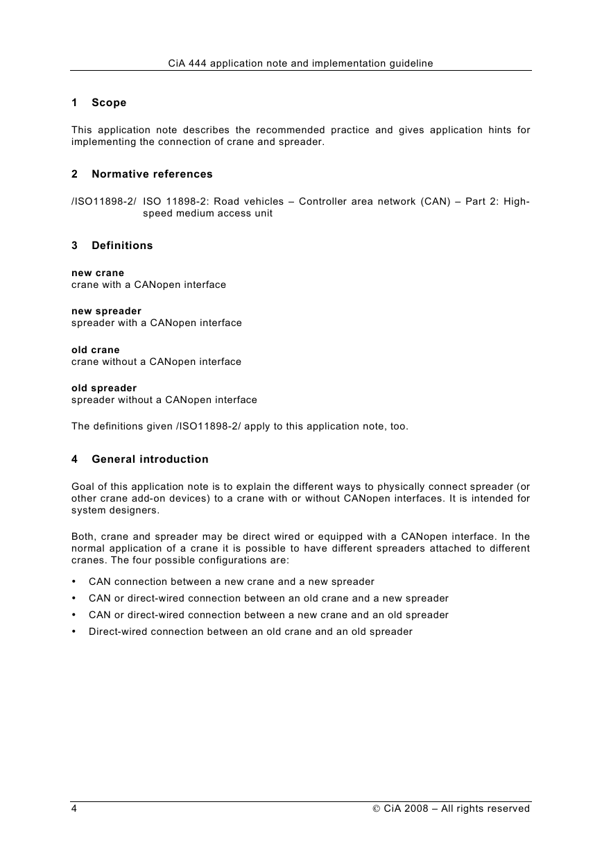
5 CAN connection between a new crane and a new spreader
CAN connection between a new crane and a new spreader may be performed as shown in
Figure 1.
Figure 1 – CAN connection between a new crane and a new spreader
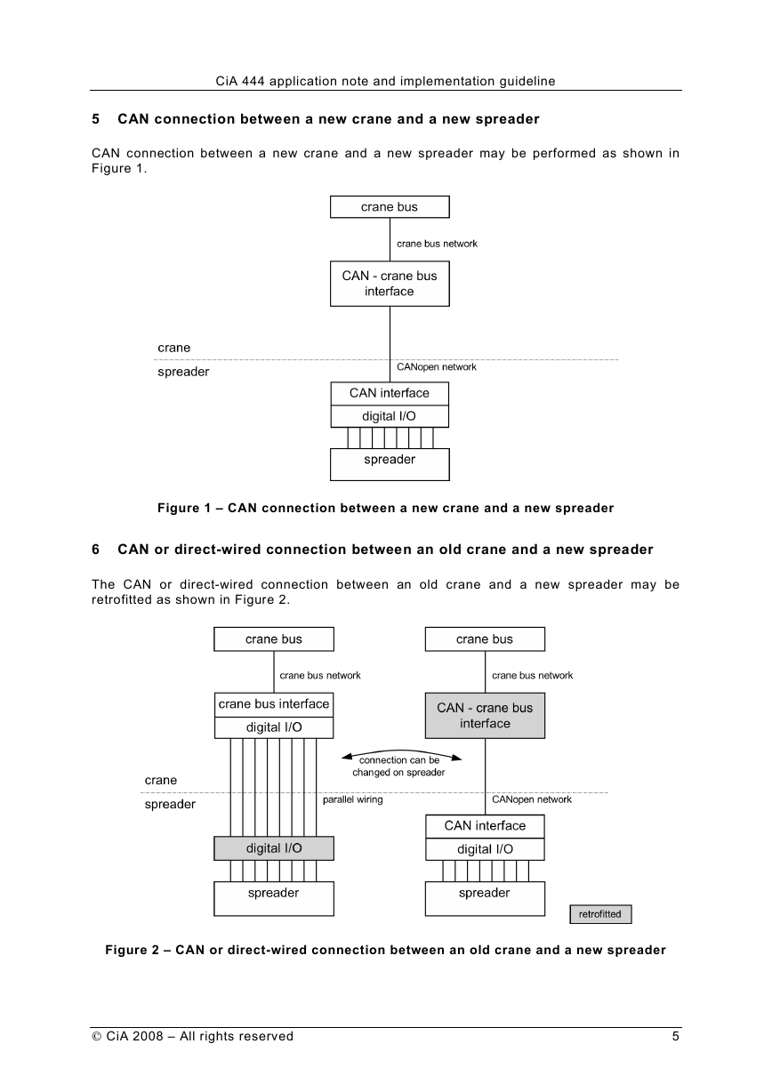
6 CAN or direct-wired connection between an old crane and a new spreader
The CAN or direct-wired connection between an old crane and a new spreader may be
retrofitted as shown in Figure 2.
Figure 2 – CAN or direct-wired connection between an old crane and a new spreader
CiA 2008 – All rights reserved
5
�
CiA 444 application note and implementation guideline
7 CAN or direct-wired connection between a new crane and an old spreader
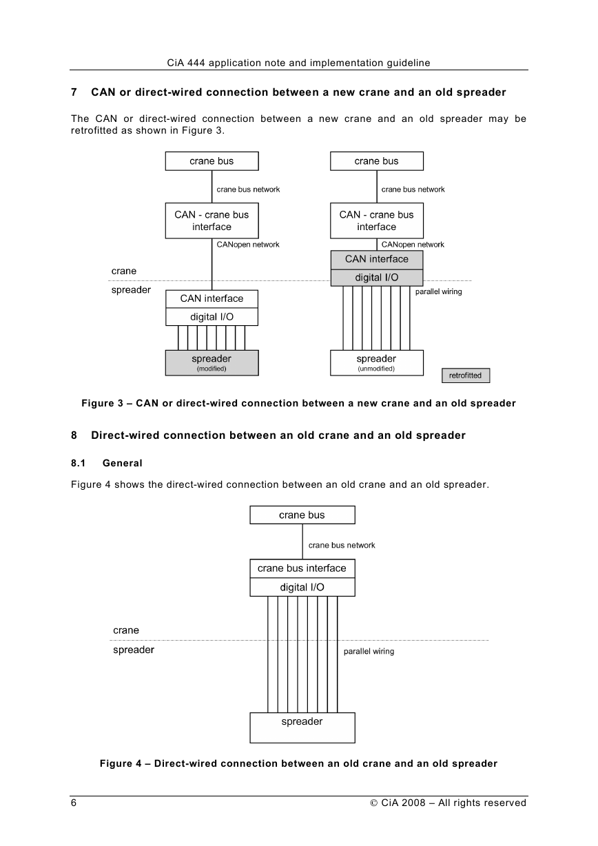
The CAN or direct-wired connection between a new crane and an old spreader may be
retrofitted as shown in Figure 3.
Figure 3 – CAN or direct-wired connection between a new crane and an old spreader
8 Direct-wired connection between an old crane and an old spreader
8.1 General
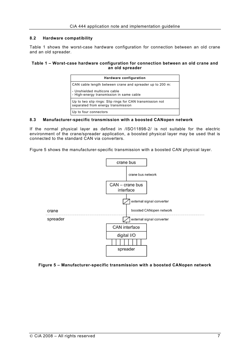
Figure 4 shows the direct-wired connection between an old crane and an old spreader.
Figure 4 – Direct-wired connection between an old crane and an old spreader
6
CiA 2008 – All rights reserved
�
CiA 444 application note and implementation guideline
8.2 Hardware compatibility
Table 1 shows the worst-case hardware configuration for connection between an old crane
and an old spreader.
Table 1 – Worst-case hardware configuration for connection between an old crane and
an old spreader
Hardware configuration
CAN cable length between crane and spreader up to 200 m:
- Unshielded multicore cable
- High-energy transmission in same cable
Up to two slip rings: Slip rings for CAN transmission not
separated from energy transmission
Up to four connectors
8.3 Manufacturer-specific transmission with a boosted CANopen network
If the normal physical layer as defined in /ISO11898-2/ is not suitable for the electric
environment of the crane/spreader application, a boosted physical layer may be used that is
connected to the standard CAN via converters.
Figure 5 shows the manufacturer-specific transmission with a boosted CAN physical layer.
Figure 5 – Manufacturer-specific transmission with a boosted CANopen network
CiA 2008 – All rights reserved
7
�
