CiA Application Note 802
CANopen
CAN remote frames
Avoiding of usage
Version: 1.0
22 Aug 2005
CAN in Automation (CiA) e. V.
�
HISTORY
Date
2005-08-22
CAN remote frames – Avoiding of usage
Changes
Publication of Version 1.0
General information on licensing and patents
CAN in AUTOMATION (CiA) calls attention to the possibility that some of the elements of this
CiA specification may be subject of patent rights. CiA shall not be responsible for identifying
any or all such patent rights.
Because this specification is licensed free of charge, there is no warranty for this
specification, to the extent permitted by applicable law. Except when otherwise stated in
writing the copyright holder and/or other parties provide this specification “as is” without
warranty of any kind, either expressed or implied, including, but not limited to, the implied
warranties of merchantability and fitness for a particular purpose. The entire risk as to the
correctness and completeness of the specification is with you. Should this specification prove
failures, you assume the cost of all necessary servicing, repair or correction.
© CiA 2008
All rights reserved. Unless otherwise specified, no part of this publication may be reproduced or
utilized in any form or by any means, electronic or mechanical, including photocopying and microfilm,
without permission in writing from CiA at the address below.
CAN in Automation e. V.
Kontumazgarten 3
DE - 90429 Nuremberg, Germany
Tel.: +49-911-928819-0
Fax: +49-911-928819-79
Url: www.can-cia.org
Email: headquarters@can-cia.org
2
CiA 2008 – All rights reserved
�
CAN remote frames – Avoiding of usage
CONTENTS
1 Scope ............................................................................................................................... 4
2
Introduction....................................................................................................................... 4
3 General problems ............................................................................................................. 5
4 Usage of CAN remote frames in CANopen ........................................................................ 5
4.1 General ................................................................................................................... 5
4.2 Network management .............................................................................................. 5
4.3 Polling of process data objects ................................................................................ 7
4.3.1 General ....................................................................................................... 7
4.3.2 Centralized scheduling of PDOs .................................................................. 7
4.3.3 Decentralized scheduling of PDOs............................................................... 7
CiA 2008 – All rights reserved
3
�
CAN remote frames – Avoiding of usage
1 Scope
This application note provides recommendations for substituting CAN remote frames by other
CANopen communication services. It should be regarded as a clear statement to avoid the
usage of CAN remote frames.
2
Introduction
The CAN data link layer defines communication services. This includes remotely requested
transmission of CAN data frames. The corresponding protocol is named CAN remote frame.
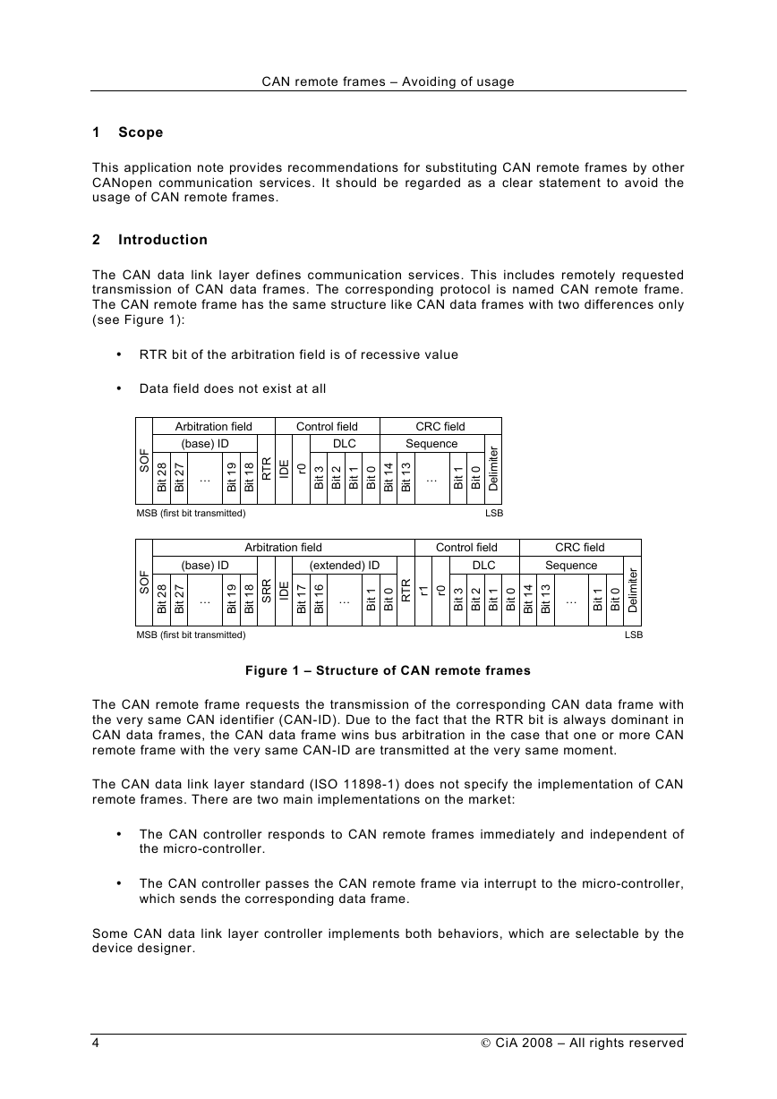
The CAN remote frame has the same structure like CAN data frames with two differences only
(see Figure 1):
• RTR bit of the arbitration field is of recessive value
• Data field does not exist at all
Figure 1 – Structure of CAN remote frames
The CAN remote frame requests the transmission of the corresponding CAN data frame with
the very same CAN identifier (CAN-ID). Due to the fact that the RTR bit is always dominant in
CAN data frames, the CAN data frame wins bus arbitration in the case that one or more CAN
remote frame with the very same CAN-ID are transmitted at the very same moment.
The CAN data link layer standard (ISO 11898-1) does not specify the implementation of CAN
remote frames. There are two main implementations on the market:
• The CAN controller responds to CAN remote frames immediately and independent of
the micro-controller.
• The CAN controller passes the CAN remote frame via interrupt to the micro-controller,
which sends the corresponding data frame.
Some CAN data link layer controller implements both behaviors, which are selectable by the
device designer.
4
CiA 2008 – All rights reserved
SOFBit 28Bit 27(base) IDArbitration field…Bit 19Bit 18SRRIDEBit 17Bit 16(extended) ID…Bit 1Bit 0RTRr1r0Bit 3Bit 2Bit 1Bit 0DLCControl fieldBit 14Bit 13Sequence…Bit 1Bit 0DelimiterCRC fieldSOFBit 28Bit 27(base) IDArbitration field…Bit 19Bit 18RTRIDEr0Bit 3Bit 2Bit 1Bit 0DLCControl fieldBit 14Bit 13Sequence…Bit 1Bit 0DelimiterCRC fieldLSBMSB (first bit transmitted)LSBMSB (first bit transmitted)�
CAN remote frames – Avoiding of usage
3 General problems
In the following some general problems are listed which arises with some CAN controllers
when processing CAN remote frames:
• The number of transmit messages supporting CAN remote frames is limited as on
some CAN controllers the global receive buffer are not able to handle RTR-requests
and therefore e.g. only up to 14 or sometimes even less RTR-messages are handled.
• The implementation effort of the CAN software driver is more complex as the CAN
remote frame is relatively complex to handle on some CAN controllers. On some CAN
controllers with single message buffering capability, CAN remote frames have to be
transmitted via a receive buffer and not via a transmit buffer. If there are more CAN
remote frames to be handled than receive buffers available, the CAN remote frame is
either received in the buffer, which transmitted the CAN remote frame or in the global
receive buffer.
• When two or more devices request the CAN data frame at the very same moment, a
bus collision occurs when the data length codes are different as for arbitration only the
CAN identifier bits and the RTR bit are used. From this it follows, e.g. when two or
more devices request the same CAN data frame, all receive message buffers linked to
this CAN data frame shall have the same data length.
• Furthermore some CAN controllers with single message buffer capability respond to a
CAN remote frame with the corresponding message with the same data length code
received by the CAN remote frame and not with the data length provided when the
message was configured.
4 Usage of CAN remote frames in CANopen
4.1 General
From the beginning, the usage of CAN remote frames was restricted in CANopen. CAN
remote frames are only allowed for the NMT (network management) node-guarding function
and for remotely requested PDOs (process data objects). The usage of CAN remote frames
for SDO (service data object), EMCY (emergency), TIME (time-stamp), NMT (network
management), SRDO (safety-related data object) protocols is not allowed at all.
4.2 Network management
It is recommended to use the Heartbeat mechanism to supervise CANopen NMT slave
devices.
With the NMT node-guarding mechanism the device with NMT master functionality supervises
all CANopen NMT slave devices in the network. Therefore the NMT master transmits
periodically the node-guarding request as CAN remote frame to each slave, which responds
with its corresponding node-guarding response as CAN data frame (see Figure 2).
The node-guarding response message contains the NMT FSA (finite state automaton) status
information plus an additional toggle-bit. The toggle-bit is necessary to detect that the micro-
controller is not more updating the status information if the CAN controller responds
automatically without interference of the micro-controller.
CiA 2008 – All rights reserved
5
�
CAN remote frames – Avoiding of usage
Figure 2 – Node guarding protocol
This node-guarding mechanism has the disadvantage that only the device with NMT master
functionality receives the node-guarding messages. Therefore, version 4.0 of the CANopen
application layer introduced the heartbeat mechanism. Each CANopen NMT slave device
sends periodically its heartbeat message as CAN data frame. This message contains the
current NMT FSA state but without the toggle bit. The heartbeat may be received and
monitored by all other CANopen NMT slave devices and of course the device with NMT
master functionality (see Figure 3).
Figure 3 – Heartbeat protocol
Advantages of the heartbeat mechanism:
• Reduced busload as no CAN remote frame is necessary.
6
CiA 2008 – All rights reserved
NMT master NMT slaveToggle-bit Node StateconfirmationresponseToggle-bit Node StateBit 7 Bit 6 - 0confirmationresponseRemote framerequestindicationrequestindicationRemote frameindicationNode eventGuard-time (100Ch)Life-time factor (100Dh)Network eventindicationCAN-ID = 1793 to 1919Bit 7 Bit 6 - 0CAN-ID = 1793 to 1919 (DLC = 1)Heartbeat producerHeartbeat consumer(s)Heartbeatproducertime (1017h)in msHeartbeatconsumertime (1016h)in msrequestindication(s)Node stateindication(s)requestNode stateCAN-ID = 1793 to 1919HeartbeateventindicationNode state values: 4 = Stopped 5 = Operational127 = Pre-operationalDLC = 1�
CAN remote frames – Avoiding of usage
• CANopen NMT slaves monitors directly other CANopen devices (faster reaction time
compared to the NMT-master reporting node failures to the remaining slaves).
• Decentralized monitoring is better than centralized monitoring in case the device with
NMT master functionality fails.
Disadvantages of the node-guarding mechanism:
• After sending the CANopen boot-up message, the transmit message buffer on CAN
controller chips with single message buffers needs to be reloaded with the new data
for node-guarding. When however the node-guarding message has already been
requested by the NMT-master by means of a CAN remote frame before the transmit
message buffer is updated, the previous buffer transmits the boot-up message again.
4.3
Polling of process data objects
4.3.1
General
In particular in PLC-based control systems, the transmission of PDOs should be scheduled by
the progression of
frequency. CANopen provides several scheduling
mechanism to achieve such behaviour. It is not recommended to use CAN remote frames for
this purpose.
in defined
time
4.3.2
Centralized scheduling of PDOs
If a centralized scheduling of PDOs is required, it is recommended to use synchronous PDOs.
The Sync message is than the trigger for updating the mapped objects as well as for the PDO
transmission. The system designer has the possibility to define that the synchronous PDO
serves all received Sync messages or only every second, every third etc. The lowest
frequency is to serve every 240th Sync message.
In order to reduce busloads, the system designer may use the acyclic transmission of PDOs.
Acyclic transmission means that in addition to the reception of the Sync message an internal
event (e.g. change of state) has to be occurred in order to cause a PDO transmission.
4.3.3
Decentralized scheduling of PDOs
If a decentralized scheduling of PDOs is required, it is recommended to use event-timer
triggered PDOs. A typical application for requesting PDOs by CAN remote frames would be
when a newly connected HMI (human machine interface) device immediately retrieves all
necessary process data from the other CANopen NMT slaves in the network. This is
especially important if the PDOs are only transmitted “on change” (event-triggered) of the
input value, but this may take some time.
To be able to retrieve the process data on one side but to avoid the use of CAN remote
frames on the other side, the PDO event timer mechanism should be used. With this
mechanism for each TPDO an individual time is configurable when the PDO is re-transmitted
even if the corresponding process data is not changing.
If periodically transmission is required, the PDO inhibit-timer may be used in addition. In order
to avoid problems, it is recommended to configure a minimum time-window between inhibit-
timer and event-timer (e.g. 9 ms for inhibit-timer and 10 ms for event-timer).
CiA 2008 – All rights reserved
7
�
