CiA Draft Standard 418
CANopen
Device profile for battery modules
Version 1.0.1
01 January 2005
© CAN in Automation (CiA) e. V.
�
DS 418 V1.0.1
CANopen device profile for battery modules
CiA
Version
1.0
1.0.1
Changes
Released as Draft Standard Proposal
Publication as Draft Standard
• Partly re-chaptered
• Minor editorial corrections
• Detailed description of PDO parameters
History
Date
2002-10-06
2005-01-01
General information on licensing and patents
CAN in AUTOMATION (CiA) calls attention to the possibility that some of the elements of this CiA
specification may be subject of patent rights. CiA shall not be responsible for identifying any or all such
patent rights.
Because this specification is licensed free of charge, there is no warranty for this
specification, to the extent permitted by applicable law. Except when otherwise stated in
writing the copyright holder and/or other parties provide this specification “as is” without
warranty of any kind, either expressed or implied, including, but not limited to, the implied
warranties of merchantability and fitness for a particular purpose. The entire risk as to the
correctness and completeness of the specification is with you. Should this specification prove
failures, you assume the cost of all necessary servicing, repair or correction.
© CiA 2008
All rights reserved. Unless otherwise specified, no part of this publication may be reproduced or
utilized in any form or by any means, electronic or mechanical, including photocopying and microfilm,
without permission in writing from CiA at the address below.
CAN in Automation e. V.
Kontumazgarten 3
DE - 90429 Nuremberg, Germany
Tel.: +49-911-928819-0
Fax: +49-911-928819-79
Url: www.can-cia.org
Email: headquarters@can-cia.org
ii
© CiA 2008 – All rights reserved
�
DS 418 V1.0.1
CANopen device profile for battery modules
CiA
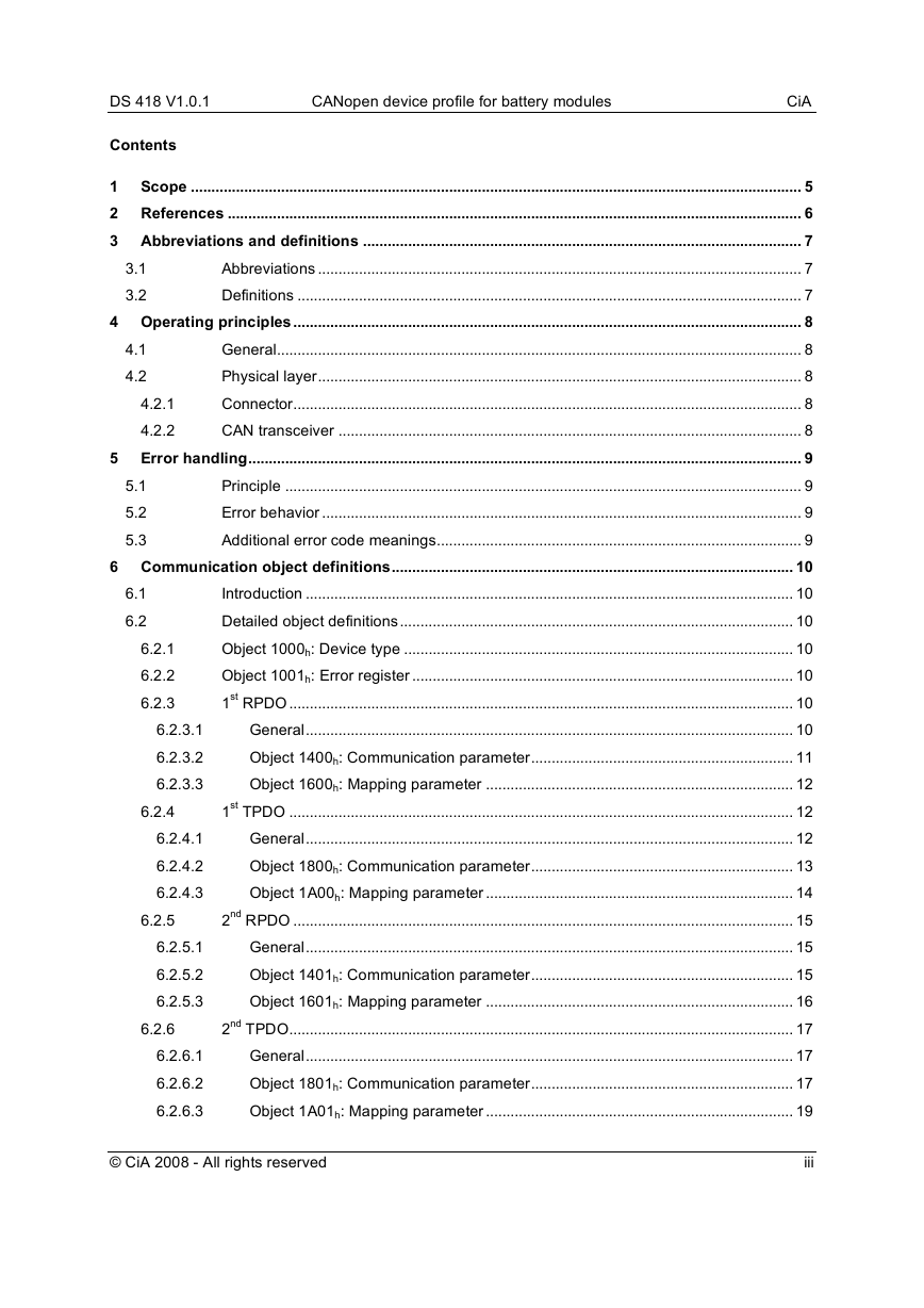
Contents
1 Scope ..................................................................................................................................................... 5
2 References ............................................................................................................................................ 6
3 Abbreviations and definitions ........................................................................................................... 7
3.1
Abbreviations ...................................................................................................................... 7
3.2
Definitions ........................................................................................................................... 7
4 Operating principles............................................................................................................................ 8
4.1
General................................................................................................................................ 8
Physical layer...................................................................................................................... 8
4.2
Connector............................................................................................................................ 8
4.2.1
4.2.2
CAN transceiver ................................................................................................................. 8
5 Error handling....................................................................................................................................... 9
Principle .............................................................................................................................. 9
5.1
5.2
Error behavior ..................................................................................................................... 9
5.3
Additional error code meanings......................................................................................... 9
6 Communication object definitions.................................................................................................. 10
6.1
Introduction ....................................................................................................................... 10
Detailed object definitions................................................................................................ 10
6.2
Object 1000h: Device type ............................................................................................... 10
6.2.1
6.2.2
Object 1001h: Error register ............................................................................................. 10
1st RPDO ........................................................................................................................... 10
6.2.3
6.2.3.1
General....................................................................................................................... 10
Object 1400h: Communication parameter................................................................ 11
6.2.3.2
6.2.3.3
Object 1600h: Mapping parameter ........................................................................... 12
1st TPDO ........................................................................................................................... 12
6.2.4
General....................................................................................................................... 12
6.2.4.1
Object 1800h: Communication parameter................................................................ 13
6.2.4.2
6.2.4.3
Object 1A00h: Mapping parameter ........................................................................... 14
2nd RPDO .......................................................................................................................... 15
6.2.5
General....................................................................................................................... 15
6.2.5.1
6.2.5.2
Object 1401h: Communication parameter................................................................ 15
Object 1601h: Mapping parameter ........................................................................... 16
6.2.5.3
2nd TPDO........................................................................................................................... 17
6.2.6
6.2.6.1
General....................................................................................................................... 17
Object 1801h: Communication parameter................................................................ 17
6.2.6.2
6.2.6.3
Object 1A01h: Mapping parameter ........................................................................... 19
© CiA 2008 - All rights reserved
iii
�
DS 418 V1.0.1
CANopen device profile for battery modules
6.2.7
6.2.7.1
6.2.7.2
6.2.7.3
6.2.8
6.2.8.1
6.2.8.2
6.2.8.3
CiA
3rd RPDO........................................................................................................................... 20
General....................................................................................................................... 20
Object 1402h: Communication parameter................................................................ 20
Object 1602h: Mapping parameter ........................................................................... 21
3rd TPDO ........................................................................................................................... 22
General....................................................................................................................... 22
Object 1802h: Communication parameter................................................................ 23
Object 1A02h: Mapping parameter ........................................................................... 24
7 Application object definitions.......................................................................................................... 26
Introduction ....................................................................................................................... 26
7.1
Complex data type definition ........................................................................................... 26
7.2
7.2.1
Record 0080h: BatteryPar................................................................................................ 26
Detailed object definitions................................................................................................ 26
7.3
7.3.1
Object 6000h: Battery status ............................................................................................ 26
Object 6001h: Charger status .......................................................................................... 27
7.3.2
Object 6010h: Temperature ............................................................................................. 28
7.3.3
7.3.4
Object 6020h: Battery parameters ................................................................................... 28
Object 6030h: Battery serial number ............................................................................... 29
7.3.5
Object 6031h: Battery ID .................................................................................................. 31
7.3.6
7.3.7
Object 6040h: Vehicle serial number............................................................................... 32
Object 6041h: Vehicle ID.................................................................................................. 33
7.3.8
Object 6050h: Cumulative total Ah charge...................................................................... 34
7.3.9
7.3.10
Object 6051h: Ah expended since last charge ............................................................... 35
Object 6052h: Ah returned during last charge ................................................................ 35
7.3.11
Object 6053h: Ah since last equalization ........................................................................ 36
7.3.12
7.3.13
Object 6054h: Date of last equalization........................................................................... 36
Object 6060h: Battery voltage.......................................................................................... 37
7.3.14
Object 6070h: Charge current requested........................................................................ 38
7.3.15
7.3.16
Object 6080h: Charger state of charge ........................................................................... 38
Object 6081h: Battery state of charge ............................................................................. 39
7.3.17
7.3.18
Object 6090h: Water level status ..................................................................................... 40
Appendix A (normative): Battery type parameter ................................................................................ 41
Appendix B (normative): Pilot signal..................................................................................................... 44
Appendix C (informative): Overview on application objects ............................................................. 45
iv
© CiA 2008 – All rights reserved
�
DS 418 V1.0.1
CANopen device profile for battery modules
CiA
1
Scope
This device profile describes a recommended practice for the communication link between a battery
module and a battery charger. The required data messages are intended to be sufficient to allow a
battery charge to be carried out. Optional data is a selection of data commonly used in the industry to
provide enhanced features. Battery modules compliant to this standard shall use communication
techniques, which conforms to those described in the CANopen application layer and communication
profile.
© CiA 2008 – All rights reserved
5
�
DS 418 V1.0.1
CANopen device profile for battery modules
CiA
2 References
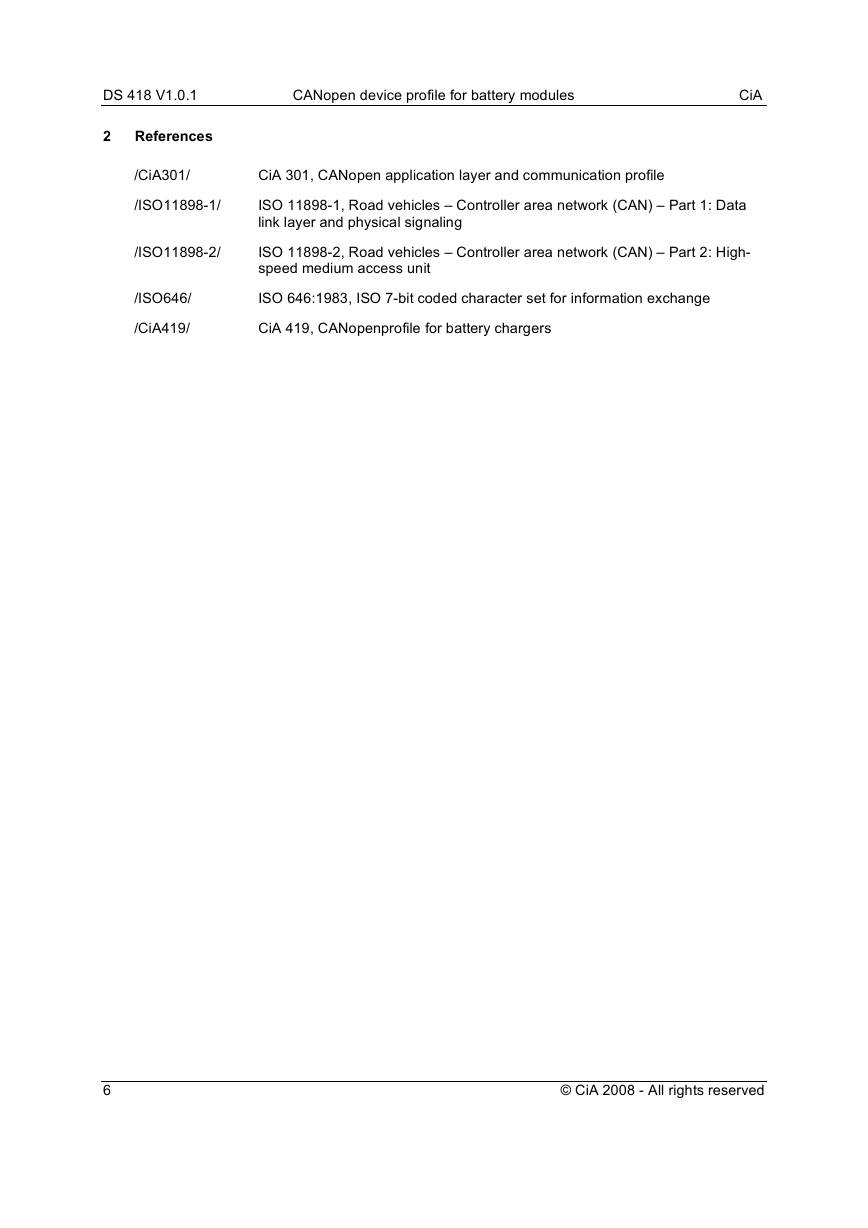
/CiA301/
CiA 301, CANopen application layer and communication profile
/ISO11898-1/
/ISO11898-2/
ISO 11898-1, Road vehicles – Controller area network (CAN) – Part 1: Data
link layer and physical signaling
ISO 11898-2, Road vehicles – Controller area network (CAN) – Part 2: High-
speed medium access unit
/ISO646/
/CiA419/
ISO 646:1983, ISO 7-bit coded character set for information exchange
CiA 419, CANopenprofile for battery chargers
6
© CiA 2008 - All rights reserved
�
DS 418 V1.0.1
CANopen device profile for battery modules
CiA
3 Abbreviations and definitions
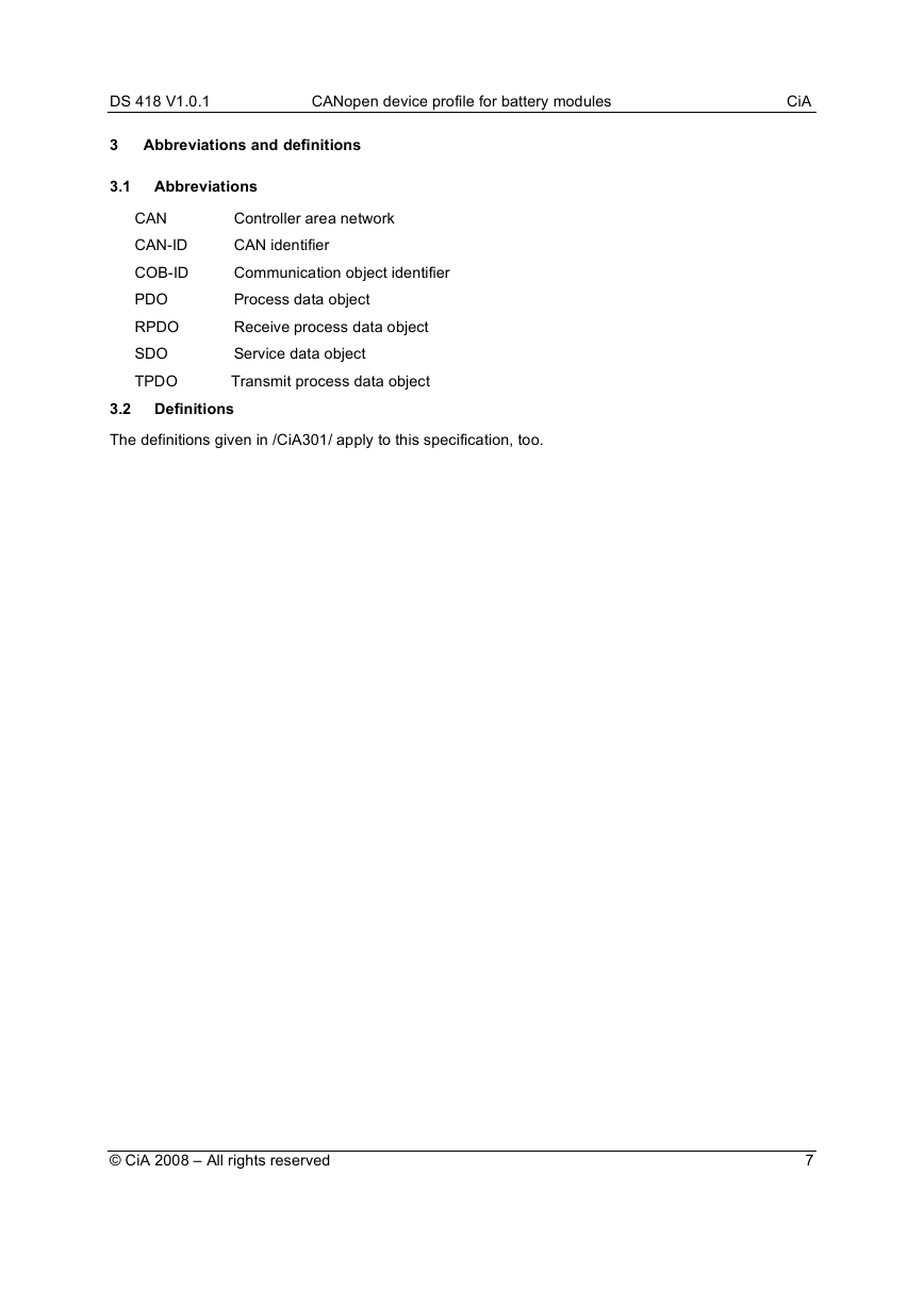
3.1 Abbreviations
CAN
CAN-ID
COB-ID
PDO
RPDO
SDO
TPDO
Controller area network
CAN identifier
Communication object identifier
Process data object
Receive process data object
Service data object
Transmit process data object
3.2 Definitions
The definitions given in /CiA301/ apply to this specification, too.
© CiA 2008 – All rights reserved
7
�
DS 418 V1.0.1
CANopen device profile for battery modules
CiA
4 Operating principles
4.1 General
The purpose of the battery module is to provide information to a charger sufficient to allow a charge to
be carried out. The minimum information required is the battery type, battery capacity, number of cells,
maximum charge current permissible, and the battery temperature. All devices conforming to this
specification shall provide this information in the manner described. Additional, optional information,
such as various identifiers, charge history data, battery voltage, battery state of charge, requested
current and water level status are also defined. Conforming devices need not supply this information,
but if they do, they shall provide it in the manner described herein.
A default TPDO is defined to send the battery temperature and status information on a timer driven
basis. Optional TPDOs are defined for transmitting battery voltage, current requests and state of
charge. A default RPDO is defined to receive charger status. An optional RPDO adds charge returned
to the data received. Battery parameter information may be read by SDO services. If the charger
supports any of the optional data items, these may be read by SDO services. If the module supports
the optional PDOs, then they can be configured via SDO services.
The battery module shall support the heartbeat function, and may optionally be a time-stamp
consumer.
4.2 Physical layer
4.2.1 Connector
The battery module shall have a 5-wire interconnect. The communications bus shall use three of these
lines (CAN_L, CAN_H, and ground), and two shall be used for the pilot signal (see appendix B). The
actual connector used and its pin configuration will vary depending on the battery’s application, and
thus is outside of the scope of this document.
4.2.2 CAN transceiver
The CAN bus shall use standard high-speed differential transceivers compliant to /ISO11898-2/. The
battery module shall support at least the 125 kbit/s default bit-rate. A termination resistor of 124 Ohm
shall be included in the default battery module configuration.
8
© CiA 2008 - All rights reserved
�
