CiA Draft Standard 420
CANopen
Profiles for extruder downstream devices
Part 3: Corrugator
Version: 3.0
31 January 2007
CAN in Automation (CiA) e. V.
�
Profiles for extruder downstream devices – Part 3: Corrugator
Changes
Publication of version 1.0 as draft standard proposal
Publication of version 2.0 as draft standard proposal
Publication of version 3.0 as draft standard
Editorial corrections and clarifications
HISTORY
Date
2002-10-22
2004-02-27
2007-01-31
General information on licensing and patents
CAN in AUTOMATION (CiA) calls attention to the possibility that some of the elements of this
CiA specification may be subject of patent rights. CiA shall not be responsible for identifying
any or all such patent rights.
Because this specification is licensed free of charge, there is no warranty for this
specification, to the extent permitted by applicable law. Except when otherwise stated in
writing the copyright holder and/or other parties provide this specification “as is” without
warranty of any kind, either expressed or implied, including, but not limited to, the implied
warranties of merchantability and fitness for a particular purpose. The entire risk as to the
correctness and completeness of the specification is with you. Should this specification prove
failures, you assume the cost of all necessary servicing, repair or correction.
© CiA 2008
All rights reserved. Unless otherwise specified, no part of this publication may be reproduced or
utilized in any form or by any means, electronic or mechanical, including photocopying and microfilm,
without permission in writing from CiA at the address below.
CAN in Automation e. V.
Kontumazgarten 3
DE - 90429 Nuremberg, Germany
Tel.: +49-911-928819-0
Fax: +49-911-928819-79
Url: www.can-cia.org
Email: headquarters@can-cia.org
2
CiA 2008 – All rights reserved
�
Profiles for extruder downstream devices – Part 3: Corrugator
CONTENTS
1 Scope ............................................................................................................................... 4
2 References ....................................................................................................................... 4
3 Abbreviations and definitions ............................................................................................ 4
3.1 Abbreviations........................................................................................................... 4
3.2 Definitions ............................................................................................................... 4
4 Operating principles .......................................................................................................... 4
4.1 General ................................................................................................................... 4
5 PDO specification ............................................................................................................. 4
5.1 Overview ................................................................................................................. 4
5.2 First TPDO .............................................................................................................. 5
5.3 Second TPDO.......................................................................................................... 8
5.4 First RPDO ............................................................................................................ 10
6 Application object specification ....................................................................................... 12
6.1 Object 6000h: Corrugator speed actual value ......................................................... 12
6.2 Object 6001h: Corrugator speed real maximum ...................................................... 13
6.3 Object 6002h: Corrugator speed set value.............................................................. 13
6.4 Object 6003h: Corrugator speed set maximum ....................................................... 14
6.5 Object 6004h: Corrugator speed set echo .............................................................. 14
6.6 Object 6005h: Corrugator speed step ..................................................................... 15
6.7 Object 6006h: Corrugator load actual value............................................................ 15
6.8 Object 6007h: Scaling factor .................................................................................. 16
6.9 Object 6008h: Product speed ................................................................................. 16
6.10 Object 6009h: Height adjustments ......................................................................... 17
6.11 Object 600Ah: Pressure set values ........................................................................ 18
6.12 Object 600Bh: Actual temperatures........................................................................ 19
6.13 Object 6010h: Configuration word .......................................................................... 20
6.14 Object 6020h: Control word.................................................................................... 21
6.15 Object 6030h: Status word ..................................................................................... 22
CiA 2008 – All rights reserved
3
�
Profiles for extruder downstream devices – Part 3: Corrugator
1 Scope
The CANopen application profile for extruder downstream devices include several parts:
Part 1 specifies general definitions
Part 2 specifies the device profile for the puller downstream device
Part 3 specifies the device profile for the corrugator downstream device
Part 4 specifies the device profile for the saw downstream device
Part 5 specifies the device profile for the co-extruder device
Part 6 specifies the device profile for the calibration-table downstream device
Note:
All parts of
Manufacturers for the Plastics and Rubber Industries (Euromap) and is documented there as Euromap 27.
this specification have been developed
jointly with
the European Committee of Machinery
This part specifies the CANopen interface for the corrugator downstream device.
2 References
/CiA420-1/: CiA 420, CANopen profile for extruder downstream devices — Part 1: General
definitions
The references given in /CiA420-1/ apply to this specification as well.
3 Abbreviations and definitions
3.1 Abbreviations
The abbreviations given in /CiA420-1/ apply to this specification as well.
3.2 Definitions
The definitions given in /CiA420-1/ apply to this specification as well.
4 Operating principles
4.1 General
The corrugator downstream device interface shall support all mandatory functions of /CiA301/
and /CiA420-1/ as well as all mandatory functions defined in this specification.
5 PDO specification
5.1 Overview
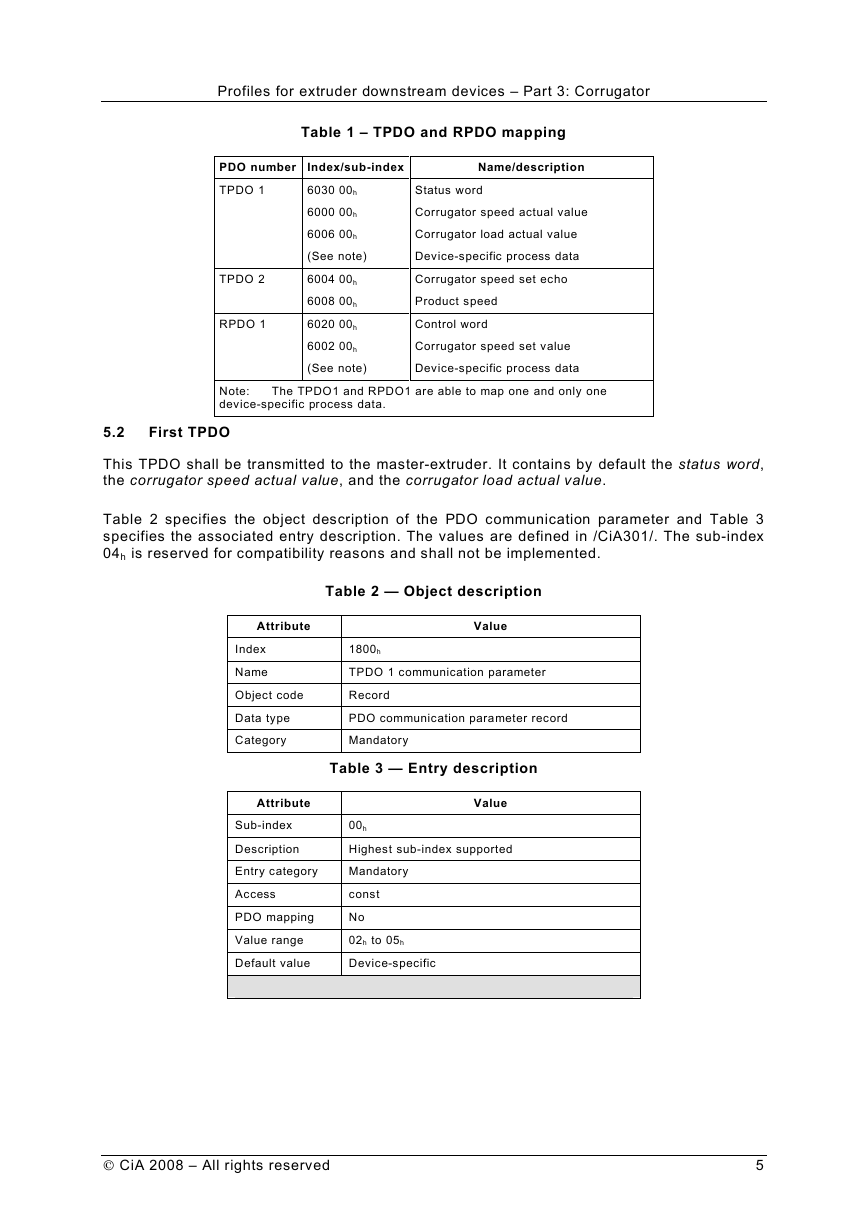
Table 1 shows the process data mapped into TPDOs and RPDOs.
4
CiA 2008 – All rights reserved
�
Profiles for extruder downstream devices – Part 3: Corrugator
PDO number
TPDO 1
TPDO 2
RPDO 1
Table 1 – TPDO and RPDO mapping
Index/sub-index
6030 00h
6000 00h
6006 00h
(See note)
6004 00h
6008 00h
6020 00h
6002 00h
(See note)
Name/description
Status word
Corrugator speed actual value
Corrugator load actual value
Device-specific process data
Corrugator speed set echo
Product speed
Control word
Corrugator speed set value
Device-specific process data
Note:
device-specific process data.
The TPDO1 and RPDO1 are able to map one and only one
5.2
First TPDO
This TPDO shall be transmitted to the master-extruder. It contains by default the status word,
the corrugator speed actual value, and the corrugator load actual value.
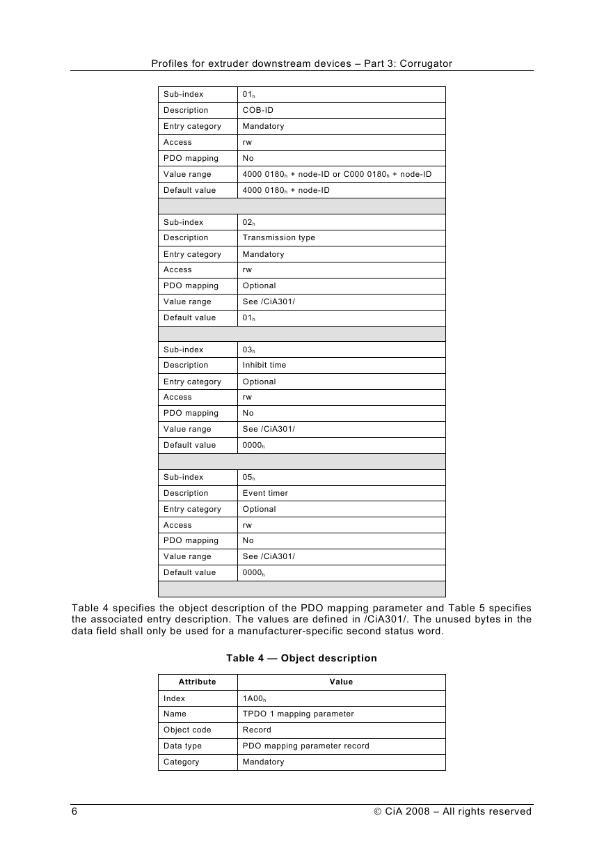
Table 2 specifies the object description of the PDO communication parameter and Table 3
specifies the associated entry description. The values are defined in /CiA301/. The sub-index
04h is reserved for compatibility reasons and shall not be implemented.
Table 2 — Object description
Attribute
Index
Name
Object code
Data type
Category
Value
1800h
TPDO 1 communication parameter
Record
PDO communication parameter record
Mandatory
Table 3 — Entry description
Attribute
Sub-index
Description
Entry category
Access
PDO mapping
Value range
Default value
Value
00h
Highest sub-index supported
Mandatory
const
No
02h to 05h
Device-specific
CiA 2008 – All rights reserved
5
�
Profiles for extruder downstream devices – Part 3: Corrugator
Sub-index
Description
Entry category
Access
PDO mapping
Value range
Default value
Sub-index
Description
Entry category
Access
PDO mapping
Value range
Default value
Sub-index
Description
Entry category
Access
PDO mapping
Value range
Default value
Sub-index
Description
Entry category
Access
PDO mapping
Value range
Default value
01h
COB-ID
Mandatory
rw
No
4000 0180h + node-ID or C000 0180h + node-ID
4000 0180h + node-ID
02h
Transmission type
Mandatory
rw
Optional
See /CiA301/
01h
03h
Inhibit time
Optional
rw
No
See /CiA301/
0000h
05h
Event timer
Optional
rw
No
See /CiA301/
0000h
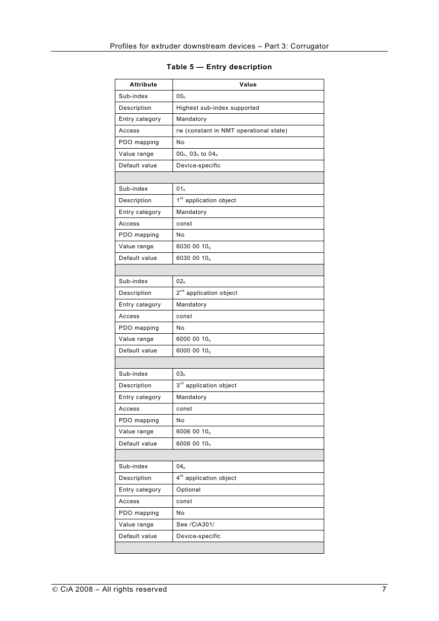
Table 4 specifies the object description of the PDO mapping parameter and Table 5 specifies
the associated entry description. The values are defined in /CiA301/. The unused bytes in the
data field shall only be used for a manufacturer-specific second status word.
Table 4 — Object description
Attribute
Index
Name
Object code
Data type
Category
Value
1A00h
TPDO 1 mapping parameter
Record
PDO mapping parameter record
Mandatory
6
CiA 2008 – All rights reserved
�
Profiles for extruder downstream devices – Part 3: Corrugator
Attribute
Sub-index
Description
Entry category
Access
PDO mapping
Value range
Default value
Sub-index
Description
Entry category
Access
PDO mapping
Value range
Default value
Sub-index
Description
Entry category
Access
PDO mapping
Value range
Default value
Sub-index
Description
Entry category
Access
PDO mapping
Value range
Default value
Sub-index
Description
Entry category
Access
PDO mapping
Value range
Default value
Table 5 — Entry description
Value
00h
Highest sub-index supported
Mandatory
rw (constant in NMT operational state)
No
00h, 03h to 04h
Device-specific
01h
1st application object
Mandatory
const
No
6030 00 10h
6030 00 10h
02h
2nd application object
Mandatory
const
No
6000 00 10h
6000 00 10h
03h
3rd application object
Mandatory
const
No
6006 00 10h
6006 00 10h
04h
4th application object
Optional
const
No
See /CiA301/
Device-specific
CiA 2008 – All rights reserved
7
�
Profiles for extruder downstream devices – Part 3: Corrugator
5.3
Second TPDO
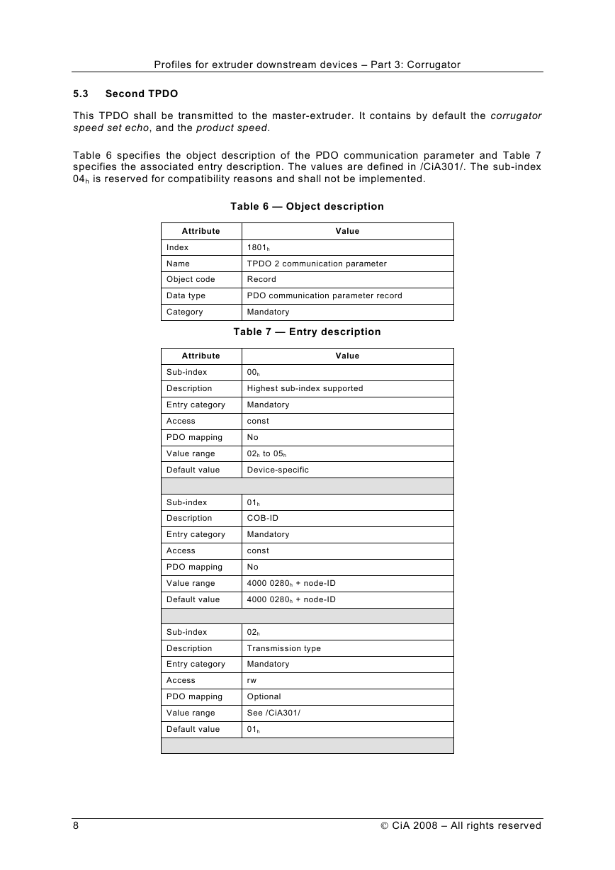
This TPDO shall be transmitted to the master-extruder. It contains by default the corrugator
speed set echo, and the product speed.
Table 6 specifies the object description of the PDO communication parameter and Table 7
specifies the associated entry description. The values are defined in /CiA301/. The sub-index
04h is reserved for compatibility reasons and shall not be implemented.
Table 6 — Object description
Attribute
Index
Name
Object code
Data type
Category
Value
1801h
TPDO 2 communication parameter
Record
PDO communication parameter record
Mandatory
Table 7 — Entry description
Attribute
Sub-index
Description
Entry category
Access
PDO mapping
Value range
Default value
Sub-index
Description
Entry category
Access
PDO mapping
Value range
Default value
Sub-index
Description
Entry category
Access
PDO mapping
Value range
Default value
Value
00h
Highest sub-index supported
Mandatory
const
No
02h to 05h
Device-specific
01h
COB-ID
Mandatory
const
No
4000 0280h + node-ID
4000 0280h + node-ID
02h
Transmission type
Mandatory
rw
Optional
See /CiA301/
01h
8
CiA 2008 – All rights reserved
�
