RemoTI Developer's Guide
Document Number: SWRU198
Copyright © 2009 Texas Instruments, Inc.
�
2.1
2.2
2.3
2.4
3.1
3.2
3.3
4.1
4.2
4.3
1.4.1
1.4.2
1.1
1.2
1.3
1.4
3.1.1
3.1.2
3.2.1
3.2.2
Table Of Contents
1 OVERVIEW..................................................................................................................................................6
INTRODUCTION........................................................................................................................................6
RF4CE ARCHITECTURE ...........................................................................................................................6
RF4CE CERTIFICATION ...........................................................................................................................7
REMOTI...................................................................................................................................................7
Stack architecture ...........................................................................................................................7
Software API...................................................................................................................................8
2 TOPOLOGY AND NODE TYPES ...........................................................................................................10
LOGICAL NODE TYPES............................................................................................................................10
TARGET .................................................................................................................................................10
CONTROLLER.........................................................................................................................................10
TOPOLOGY ............................................................................................................................................10
3 NODE CONFIGURATION.......................................................................................................................12
ADDRESSING .........................................................................................................................................12
IEEE address ................................................................................................................................12
Short address ................................................................................................................................12
STACK INITIALIZATION..........................................................................................................................12
Start modes ...................................................................................................................................12
Target cold startup .......................................................................................................................12
TYPICAL NODE STARTUP SEQUENCE USING RTI INTERFACE ..................................................................13
4 PAIRING.....................................................................................................................................................14
OVERVIEW.............................................................................................................................................14
CERC “PUSH BUTTON” PAIRING............................................................................................................14
USER CONSIDERATIONS .........................................................................................................................14
Pairing table entry........................................................................................................................14
Maximum number of entries .........................................................................................................14
Matching configuration ................................................................................................................14
Pairing with security.....................................................................................................................14
Unpair...........................................................................................................................................15
5 DATA TRANSMISSION ...........................................................................................................................16
OVERVIEW.............................................................................................................................................16
TRANSMISSION OPTIONS........................................................................................................................16
Ack/NoAck.....................................................................................................................................16
Unicast/Broadcast ........................................................................................................................16
MultiChannel or SingleChannel ...................................................................................................16
COMBINATIONS OF TRANSMISSION OPTIONS..........................................................................................16
USER CONSIDERATIONS .........................................................................................................................17
API................................................................................................................................................17
Standby mode................................................................................................................................17
6 POWER SAVINGS ....................................................................................................................................18
OVERVIEW.............................................................................................................................................18
RADIO CONTROL....................................................................................................................................18
Controller .....................................................................................................................................18
6.2.1
Target............................................................................................................................................18
6.2.2
6.3 MCU POWER CONTROL .........................................................................................................................19
Usage............................................................................................................................................19
6.3.1
6.3.2
MCU sleep with RNP....................................................................................................................19
SECURITY..................................................................................................................................................20
OVERVIEW.............................................................................................................................................20
CONFIGURATION OPTIONS .....................................................................................................................20
Enabling security..........................................................................................................................20
Key distribution ............................................................................................................................20
4.3.1
4.3.2
4.3.3
4.3.4
4.3.5
5.2.1
5.2.2
5.2.3
5.1
5.2
5.3
5.4
5.4.1
5.4.2
6.1
6.2
7
7.1
7.2
7.2.1
7.2.2
Copyright © 2009 Texas Instruments, Inc.
�
7.3
8.1
8.2
8.3
9.1
7.2.3
7.3.1
7.3.2
7.3.3
7.3.4
Key................................................................................................................................................20
USER CONSIDERATIONS .........................................................................................................................20
Key compromise............................................................................................................................20
Secure pairing range ....................................................................................................................20
Payload overhead .........................................................................................................................21
Broadcast packets.........................................................................................................................21
8 FREQUENCY AGILITY...........................................................................................................................22
OVERVIEW.............................................................................................................................................22
FREQUENCY AGILITY ............................................................................................................................22
USAGE...................................................................................................................................................22
9 GENERAL INFORMATION....................................................................................................................23
DOCUMENT HISTORY ............................................................................................................................23
ADDRESS INFORMATION.................................................................................................................23
TI WORLDWIDE TECHNICAL SUPPORT......................................................................................23
10
11
Copyright © 2009 Texas Instruments, Inc.
�
RemoTI Developer’s Guide SWRU198
References
[R1]
[R2]
[R3]
ZigBee RF4CE Specification Version 1.0 ( ZigBee Alliance document 094945r00ZB )
ZigBee RF4CE CERC Profile Specification ( ZigBee Alliance document 094946r00ZB )
IEEE Std. 802.15.4-2006, Wireless Medium Access Control (MAC) and Physical Layer
(PHY) Specifications for Low-Rate Wireless Personal Area Networks (WPANs).
CC2530 Users Guide, SWRU191, http://www.ti.com/lit/SWRU191
RemoTI API document, SWRA268
[R4]
[R5]
[R6] OSAL API document, SWRA194
[R7]
[R8]
[R9]
[R10] RemoTI SimpleApp App Note, SWRA286, http://www.ti.com/lit/SWRA286
[R11] RemoTI Power Consumption App Note, SWRA263, http://www.ti.com/lit/SWRA263
[R12] RemoTI Coexistence Testing App Note, SWRA285, http://www.ti.com/lit/SWRA285
HAL Driver API document, SWRA193
RemoTI Network Processor Interface Specification, SWRA271
RemoTI Sample Applications User’s Guide, SWRU201, http://www.ti.com/lit/SWRU201
Copyright © 2009 Texas Instruments, Inc.
�
RemoTI Developer’s Guide SWRU198
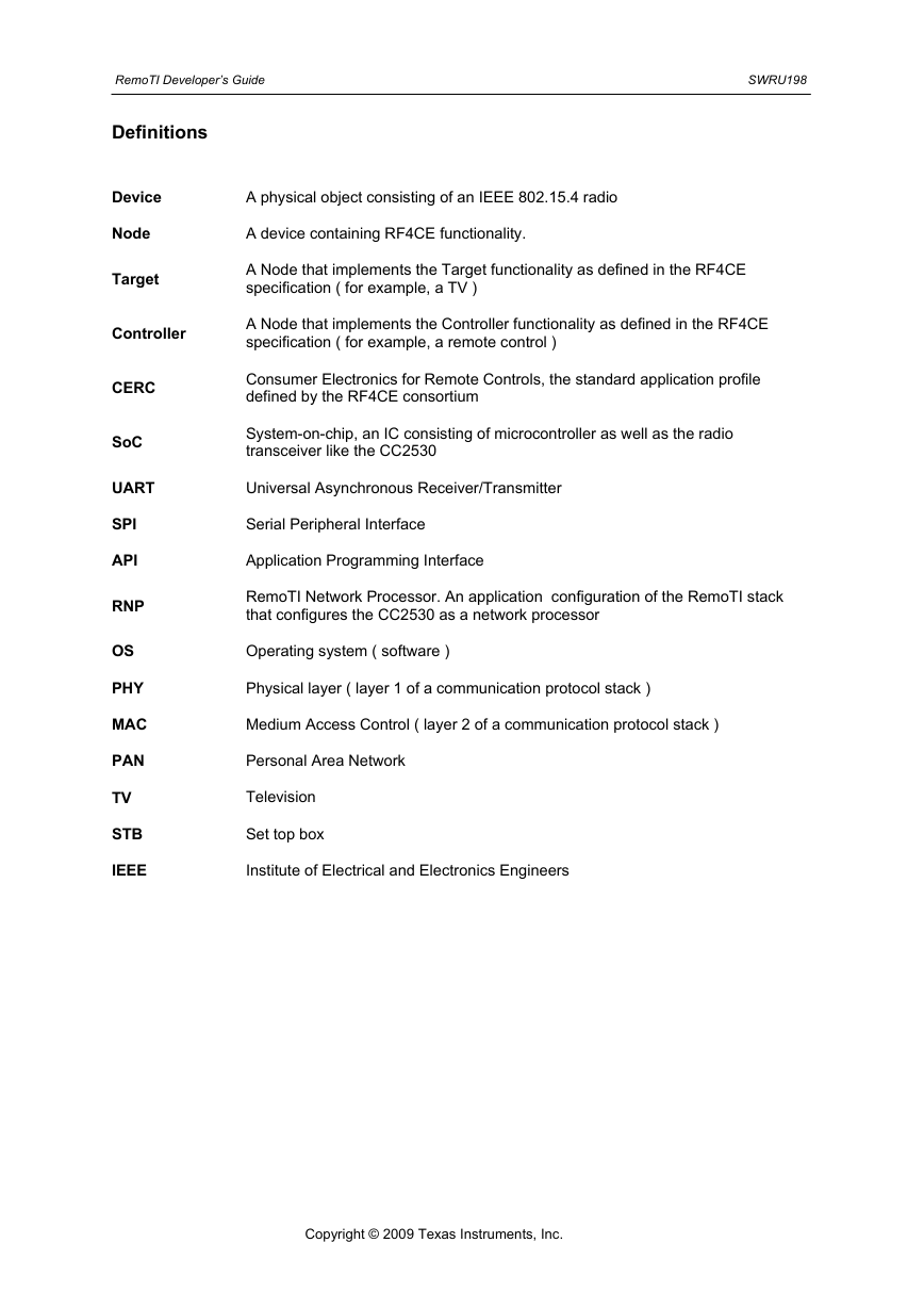
Definitions
Device
Node
Target
A physical object consisting of an IEEE 802.15.4 radio
A device containing RF4CE functionality.
A Node that implements the Target functionality as defined in the RF4CE
specification ( for example, a TV )
Controller
A Node that implements the Controller functionality as defined in the RF4CE
specification ( for example, a remote control )
Consumer Electronics for Remote Controls, the standard application profile
defined by the RF4CE consortium
System-on-chip, an IC consisting of microcontroller as well as the radio
transceiver like the CC2530
Universal Asynchronous Receiver/Transmitter
Serial Peripheral Interface
Application Programming Interface
RemoTI Network Processor. An application configuration of the RemoTI stack
that configures the CC2530 as a network processor
Operating system ( software )
Physical layer ( layer 1 of a communication protocol stack )
Medium Access Control ( layer 2 of a communication protocol stack )
Personal Area Network
Television
Set top box
Institute of Electrical and Electronics Engineers
CERC
SoC
UART
SPI
API
RNP
OS
PHY
MAC
PAN
TV
STB
IEEE
Copyright © 2009 Texas Instruments, Inc.
�
RemoTI Developer’s Guide SWRU198
1 Overview
Introduction
1.1
RF4CE (Radio Frequency for Consumer Electronics) is an industry consortium that was formed to
create a new protocol standard for RF-based remote control applications in the consumer
electronics segment. The consortium was founded by Sony, Philips, Samsung and Panasonic
with Texas Instruments, Freescale and OKI Semiconductor as the contributing members.
The first version of the network specification and application profile was completed in
December’08. Later, in March’09, the RF4CE consortium merged with the ZigBee Alliance for the
purpose of maintaining the specification going forward and managing the certification of platforms
and products that conform to the specification. The name of the specification is now ZigBee
RF4CE. For more information, see http://www.zigbee.org/rf4ce
1.2 RF4CE architecture
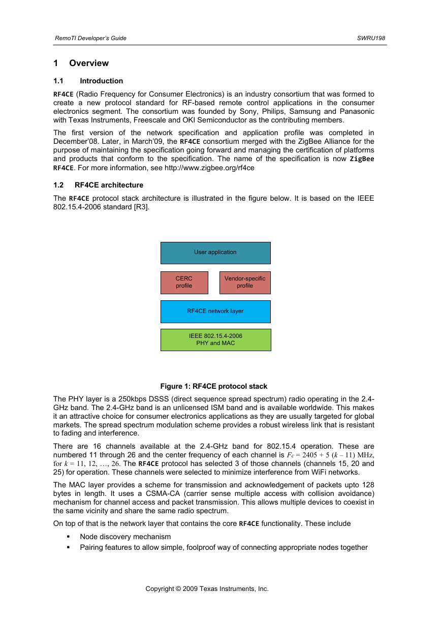
The RF4CE protocol stack architecture is illustrated in the figure below. It is based on the IEEE
802.15.4-2006 standard [R3].
User application
CERC
profile
Vendor-specific
profile
RF4CE network layer
IEEE 802.15.4-2006
PHY and MAC
Figure 1: RF4CE protocol stack
The PHY layer is a 250kbps DSSS (direct sequence spread spectrum) radio operating in the 2.4-
GHz band. The 2.4-GHz band is an unlicensed ISM band and is available worldwide. This makes
it an attractive choice for consumer electronics applications as they are usually targeted for global
markets. The spread spectrum modulation scheme provides a robust wireless link that is resistant
to fading and interference.
There are 16 channels available at the 2.4-GHz band for 802.15.4 operation. These are
numbered 11 through 26 and the center frequency of each channel is Fc = 2405 + 5 (k – 11) MHz,
for k = 11, 12, …, 26. The RF4CE protocol has selected 3 of those channels (channels 15, 20 and
25) for operation. These channels were selected to minimize interference from WiFi networks.
The MAC layer provides a scheme for transmission and acknowledgement of packets upto 128
bytes in length. It uses a CSMA-CA (carrier sense multiple access with collision avoidance)
mechanism for channel access and packet transmission. This allows multiple devices to coexist in
the same vicinity and share the same radio spectrum.
On top of that is the network layer that contains the core RF4CE functionality. These include
Node discovery mechanism
Pairing features to allow simple, foolproof way of connecting appropriate nodes together
Copyright © 2009 Texas Instruments, Inc.
�
RemoTI Developer’s Guide SWRU198
Power savings features to maximize battery life on remote controls and minimize standby
power consumption on appliances
Frequency agility mechanism to dynamically detect and avoid interference
Security features
Reliable packet transfer with multiple options and ability to carry standard and vendor-
specific profile commands
The application framework contains a standard application profile called CERC that defines most of
the commands used in simple remote control applications and is also extensible with vendor-
specific commands. It is also possible for users to define their own private profile with fully
proprietary commands.
1.3 RF4CE certification
The ZigBee Alliance has put in place a test and certification program for RF4CE products. There
are two kinds of certifications available – Platform certification and Product certification.
The platform certification is for suppliers of RF4CE hardware and software. It includes testing of the
network layer and below for compliance to the specification as well as interoperability with other
implementations. It is intended so that developers who use or evaluate RF4CE platforms from
various suppliers can be assured of the technical features supported by the platform and over-air
interoperability with platforms from other suppliers.
The product certification is an optional step for manufacturers of end products incorporating
RF4CE functionality. The purpose of this certification is to ensure that end products made by
different vendors will interoperate with each other. It is necessary to start with a certified platform
and use a standard application profile in order to achieve this certification. More details on the
certification program can be ZigBee website.
1.4 RemoTI
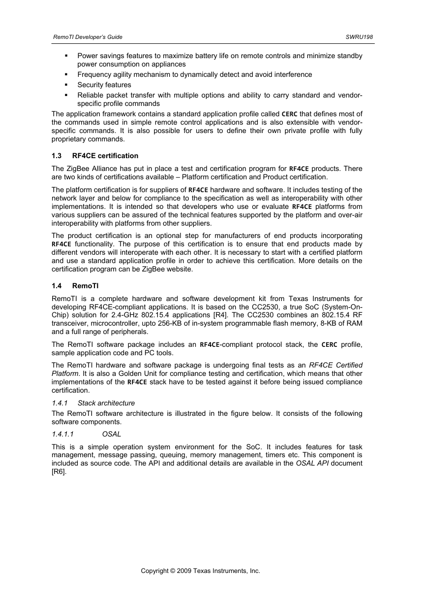
RemoTI is a complete hardware and software development kit from Texas Instruments for
developing RF4CE-compliant applications. It is based on the CC2530, a true SoC (System-On-
Chip) solution for 2.4-GHz 802.15.4 applications [R4]. The CC2530 combines an 802.15.4 RF
transceiver, microcontroller, upto 256-KB of in-system programmable flash memory, 8-KB of RAM
and a full range of peripherals.
The RemoTI software package includes an RF4CE-compliant protocol stack, the CERC profile,
sample application code and PC tools.
The RemoTI hardware and software package is undergoing final tests as an RF4CE Certified
Platform. It is also a Golden Unit for compliance testing and certification, which means that other
implementations of the RF4CE stack have to be tested against it before being issued compliance
certification.
1.4.1 Stack architecture
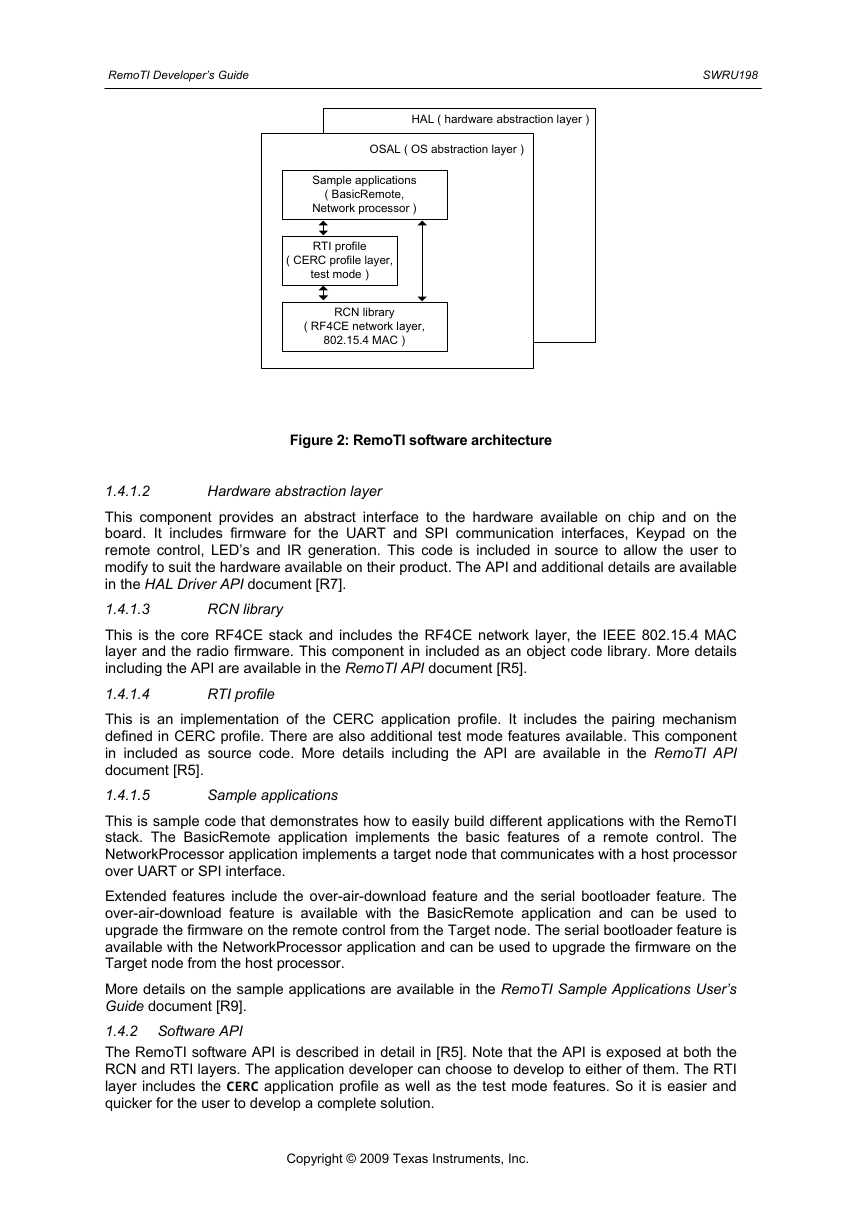
The RemoTI software architecture is illustrated in the figure below. It consists of the following
software components.
1.4.1.1
OSAL
This is a simple operation system environment for the SoC. It includes features for task
management, message passing, queuing, memory management, timers etc. This component is
included as source code. The API and additional details are available in the OSAL API document
[R6].
Copyright © 2009 Texas Instruments, Inc.
�
RemoTI Developer’s Guide SWRU198
HAL ( hardware abstraction layer )
OSAL ( OS abstraction layer )
Sample applications
( BasicRemote,
Network processor )
RTI profile
( CERC profile layer,
test mode )
RCN library
( RF4CE network layer,
802.15.4 MAC )
Figure 2: RemoTI software architecture
RTI profile
RCN library
Hardware abstraction layer
1.4.1.2
This component provides an abstract interface to the hardware available on chip and on the
board. It includes firmware for the UART and SPI communication interfaces, Keypad on the
remote control, LED’s and IR generation. This code is included in source to allow the user to
modify to suit the hardware available on their product. The API and additional details are available
in the HAL Driver API document [R7].
1.4.1.3
This is the core RF4CE stack and includes the RF4CE network layer, the IEEE 802.15.4 MAC
layer and the radio firmware. This component in included as an object code library. More details
including the API are available in the RemoTI API document [R5].
1.4.1.4
This is an implementation of the CERC application profile. It includes the pairing mechanism
defined in CERC profile. There are also additional test mode features available. This component
in included as source code. More details including the API are available in the RemoTI API
document [R5].
1.4.1.5
This is sample code that demonstrates how to easily build different applications with the RemoTI
stack. The BasicRemote application implements the basic features of a remote control. The
NetworkProcessor application implements a target node that communicates with a host processor
over UART or SPI interface.
Extended features include the over-air-download feature and the serial bootloader feature. The
over-air-download feature is available with the BasicRemote application and can be used to
upgrade the firmware on the remote control from the Target node. The serial bootloader feature is
available with the NetworkProcessor application and can be used to upgrade the firmware on the
Target node from the host processor.
More details on the sample applications are available in the RemoTI Sample Applications User’s
Guide document [R9].
1.4.2 Software API
The RemoTI software API is described in detail in [R5]. Note that the API is exposed at both the
RCN and RTI layers. The application developer can choose to develop to either of them. The RTI
layer includes the CERC application profile as well as the test mode features. So it is easier and
quicker for the user to develop a complete solution.
Sample applications
Copyright © 2009 Texas Instruments, Inc.
�
