logo资料库

MFRC522数据手册.pdf

第1页 / 共109页
第2页 / 共109页
第3页 / 共109页
第4页 / 共109页
第5页 / 共109页
第6页 / 共109页
第7页 / 共109页
第8页 / 共109页
资料共109页,剩余部分请下载后查看
1. Introduction
2. General description
3. Features
4. Quick reference data
5. Ordering information
6. Block diagram
7. Pinning information
7.1 Pinning
7.2 Pin description
8. Functional description
9. MFRC522 Register SET
9.1 MFRC522 Registers Overview
9.1.1 Register Bit Behavior
9.2 Register Description
9.2.1 Page 0: Command and Status
9.2.1.1 Reserved
9.2.1.2 CommandReg
9.2.1.3 CommIEnReg
9.2.1.4 DivIEnReg
9.2.1.5 CommIRqReg
9.2.1.6 DivIRqReg
9.2.1.7 ErrorReg
9.2.1.8 Status1Reg
9.2.1.9 Status2Reg
9.2.1.10 FIFODataReg
9.2.1.11 FIFOLevelReg
9.2.1.12 WaterLevelReg
9.2.1.13 ControlReg
9.2.1.14 BitFramingReg
9.2.1.15 CollReg
9.2.1.16 Reserved
9.2.2 Page 1: Communication
9.2.2.1 Reserved
9.2.2.2 ModeReg
9.2.2.3 TxModeReg
9.2.2.4 RxModeReg
9.2.2.5 TxControlReg
9.2.2.6 TxASKReg
9.2.2.7 TxSelReg
9.2.2.8 RxSelReg
9.2.2.9 RxThresholdReg
9.2.2.10 DemodReg
9.2.2.11 Reserved
9.2.2.12 Reserved
9.2.2.13 MfTxReg
9.2.2.14 MfRxReg
9.2.2.15 Reserved
9.2.2.16 SerialSpeedReg
9.2.3 Page 2: Configuration
9.2.3.1 Reserved
9.2.3.2 CRCResultReg
9.2.3.3 Reserved
9.2.3.4 ModWidthReg
9.2.3.5 Reserved
9.2.3.6 RFCfgReg
9.2.3.7 GsNReg
9.2.3.8 CWGsPReg
9.2.3.9 ModGsPReg
9.2.3.10 TMode Register, TPrescaler Register
9.2.3.11 TReloadReg
9.2.3.12 TCounterValReg
9.2.4 Page 3: Test
9.2.4.1 Reserved
9.2.4.2 TestSel1Reg
9.2.4.3 TestSel2Reg
9.2.4.4 TestPinEnReg
9.2.4.5 TestPinValueReg
9.2.4.6 TestBusReg
9.2.4.7 AutoTestReg
9.2.4.8 VersionReg
9.2.4.9 AnalogTestReg
9.2.4.10 TestDAC1Reg
9.2.4.11 TestDAC2Reg
9.2.4.12 TestADCReg
9.2.4.13 Reserved
10. DIGITAL Interfaces
10.1 Automatic m-Controller Interface Type Detection
10.2 SPI Compatible interface
10.2.1 General
10.2.2 Read data
10.2.3 Write data
10.2.4 Address byte
10.3 UART Interface
10.3.1 Connection to a host
10.3.2 Selection of the transfer speeds
10.3.3 Framing
10.4 I2C Bus Interface
10.4.1 General
10.4.2 Data validity
10.4.3 START and STOP conditions
10.4.4 Byte format
10.4.5 Acknowledge
10.4.6 7-BIT ADDRESSING
10.4.7 Register Write Access
10.4.8 Register Read Access
10.4.9 HS mode
10.4.10 High Speed Transfer
10.4.11 Serial Data transfer Format in HS mode
10.4.12 Switching from F/S to HS mode and Vice Versa
10.4.13 MFRC522 at Lower Speed modes
11. Analog Interface and Contactless UART
11.1 General
11.2 TX Driver
11.3 Serial Data Switch
11.4 MFIN/MFOUT interface support
11.5 CRC co-processor
12. FIFO Buffer
12.1 Overview
12.2 Accessing the FIFO Buffer
12.3 Controlling the FIFO-Buffer
12.4 Status Information about the FIFO-Buffer
13. Timer Unit
14. Interrupt Request System
15. Oscillator Circuitry
16. Power Reduction modes
16.1 Hard Power-down
16.2 Soft Power-down
16.3 Transmitter Power-down
17. Reset and Oscillator Startup Time
17.1 Reset Timing Requirements
17.2 Oscillator Startup Time
18. MFRC522 Command Set
18.1 General Description
18.2 General Behavior
18.3 MFRC522 Commands Overview
18.3.1 MFRC522 Command Description
18.3.1.1 Idle Command
18.3.1.2 Mem Command
18.3.1.3 Generate RandomID Command
18.3.1.4 CalcCRC Command
18.3.1.5 Transmit Command
18.3.1.6 NoCmdChange Command
18.3.1.7 Receive Command
18.3.1.8 Transceive Command
18.3.1.9 MFAuthent Command
18.3.1.10 SoftReset Command
19. Testsignals
19.1 Selftest
19.2 Test bus
19.3 Testsignals at pin AUX
19.3.1 Example: Output TestDAC 1 on AUX1 and TestDAC 2 on AUX2
19.3.2 Example: Output Testsignal Corr1 on AUX1 and MinLevel on AUX2
19.3.3 Example: Output ADC channel I on AUX 1 and ADC channel Q on AUX 2
19.3.4 Example: Output RxActive on AUX 1 and TxActive on AUX 2
19.3.5 Example: Output Rx Data Stream on AUX 1 and AUX 2
19.4 PRBS (Pseudo-Random Binary Sequence)
20. Limiting values
21. Recommended operating conditions
22. Thermal characteristics
23. Characteristics
23.1 Input Pin Characteristics
23.1.1 Input Pin characteristics for pins EA, I2C and NRESET
23.1.2 Input Pin characteristics for pin MFIN
23.1.3 Input/Output Pin characteristics for pins D1, D2, D3, D4, D5, D6 and D7
23.1.4 Input Pin characteristics for pin SDA
23.1.5 Output Pin characteristics for Pin MFOUT
23.1.6 Output Pin characteristics for Pin IRQ
23.1.7 Input Pin characteristics for Pin Rx
23.1.8 Input Pin characteristics for pin OSCIN
23.1.9 Output Pin characteristics for Pins AUX1 and AUX2
23.1.10 Output Pin characteristics for Pins TX1 and TX2
23.2 Current Consumption
23.3 RX Input Voltage Range
23.4 RX Input Sensitivity
23.5 Clock Frequency
23.6 XTAL Oscillator
23.7 Typical 27.12 MHz Crystal Requirements
23.8 Timing for the SPI compatible interface
23.9 I2C Timing
24. Application information
25. Package outline
26. Handling information
27. Packing information
28. Abbreviations
29. References
30. Revision history
31. Legal information
31.1 Data sheet status
31.2 Definitions
31.3 Disclaimers
31.4 Trademarks
32. Contact information
33. Tables
34. Figures
35. Contents
MFRC522 Contactless Reader IC Rev. 3.2 — 22 May 2007 112132 Product data sheet PUBLIC INFORMATION 1. Introduction This document describes the functionality of the contactless reader/writer MFRC522. It includes the functional and electrical specifications. 2. General description The MFRC522 is a highly integrated reader/writer for contactless communication at 13.56 MHz. The MFRC522 reader supports ISO 14443A / MIFARE® mode. The MFRC522’s internal transmitter part is able to drive a reader/writer antenna designed to communicate with ISO/IEC 14443A/MIFARE® cards and transponders without additional active circuitry. The receiver part provides a robust and efficient implementation of a demodulation and decoding circuitry for signals from ISO/IEC 14443A/MIFARE® compatible cards and transponders. The digital part handles the complete ISO/IEC 14443A framing and error detection (Parity & CRC).The MFRC522 supports MIFARE®Classic (e.g. MIFARE® Standard) products. The MFRC522 supports contactless communication using MIFARE® higher transfer speeds up to 848 kbit/s in both directions. Various host interfaces are implemented: • SPI interface • serial UART (similar to RS232 with voltage levels according pad voltage supply) • I2C interface. Highly integrated analog circuitry to demodulate and decode responses Buffered output drivers to connect an antenna with minimum number of external components Supports ISO/IEC 14443A / MIFARE® Typical operating distance in Reader/Writer mode for communication to a ISO/IEC 14443A / MIFARE® up to 50 mm depending on the antenna size and tuning Supports MIFARE® Classic encryption in Reader/Writer mode Supports ISO/IEC 14443A higher transfer speed communication up to 848 kbit/s Support of the MFIN / MFOUT Additional power supply to directly supply the smart card IC connected via MFIN / MFOUT Supported host interfaces 3. Features
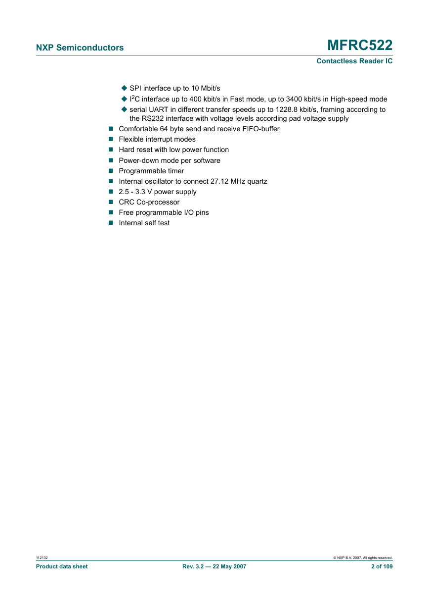
NXP Semiconductors MFRC522 Contactless Reader IC SPI interface up to 10 Mbit/s I2C interface up to 400 kbit/s in Fast mode, up to 3400 kbit/s in High-speed mode serial UART in different transfer speeds up to 1228.8 kbit/s, framing according to the RS232 interface with voltage levels according pad voltage supply Comfortable 64 byte send and receive FIFO-buffer Flexible interrupt modes Hard reset with low power function Power-down mode per software Programmable timer Internal oscillator to connect 27.12 MHz quartz 2.5 - 3.3 V power supply CRC Co-processor Free programmable I/O pins Internal self test 112132 Product data sheet Rev. 3.2 — 22 May 2007 © NXP B.V. 2007. All rights reserved. 2 of 109
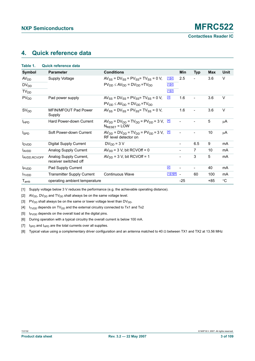
NXP Semiconductors 4. Quick reference data Table 1. Symbol AVDD DVDD TVDD PVDD SVDD IHPD ISPD Quick reference data Parameter Supply Voltage Pad power supply MFIN/MFOUT Pad Power Supply Hard Power-down Current Soft Power-down Current Digital Supply Current IDVDD Analog Supply Current IAVDD IAVDD,RCVOFF Analog Supply Current, IPVDD ITVDD Tamb receiver switched off Pad Supply Current Transmitter Supply Current operating ambient temperature MFRC522 Contactless Reader IC Min 2.5 Typ - Max 3.6 Unit V - - - - 6.5 7 3 - 60 3.6 3.6 5 10 9 10 5 40 100 +85 V V μA μA mA mA mA mA mA °C Conditions AVSS = DVSS = PVSS= TVSS = 0 V, PVDD ≤ AVDD = DVDD =TVDD AVSS = DVSS = PVSS= TVSS = 0 V, PVDD ≤ AVDD = DVDD =TVDD AVSS = DVSS = PVSS= TVSS = 0 V, AVDD = DVDD = TVDD = PVDD = 3 V, NRESET = LOW AVDD = DVDD = TVDD = PVDD = 3 V, RF level detector on DVDD = 3 V AVDD = 3 V, bit RCVOff = 0 AVDD = 3 V, bit RCVOff = 1 [1][2] [1][2] [1][2] [3] [4] [4] 1.6 1.6 - - - - - Continuous Wave [2] [1][3][8] - - -25 [1] Supply voltage below 3 V reduces the performance (e.g. the achievable operating distance). [2] AVDD, DVDD and TVDD shall always be on the same voltage level. [3] PVDD shall always be on the same or lower voltage level than DVDD. [4] [5] [6] During operation with a typical circuitry the overall current is below 100 mA. [7] [8] Typical value using a complementary driver configuration and an antenna matched to 40 Ω between TX1 and TX2 at 13.56 MHz ITVDD depends on TVDD and the external circuitry connected to Tx1 and Tx2 IPVDD depends on the overall load at the digital pins. ISPD and IHPD are the total currents over all supplies. 112132 Product data sheet Rev. 3.2 — 22 May 2007 © NXP B.V. 2007. All rights reserved. 3 of 109
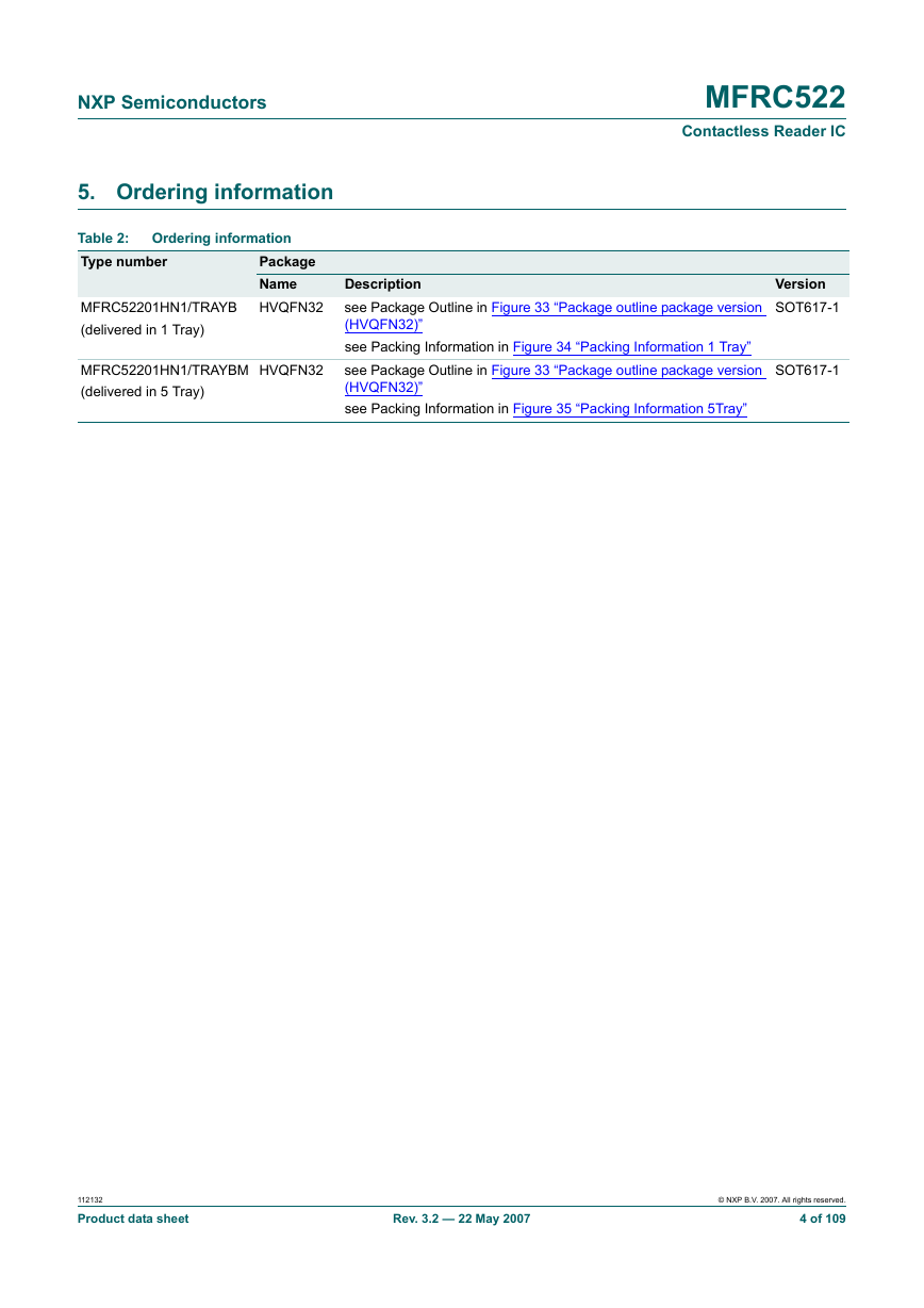
NXP Semiconductors 5. Ordering information MFRC522 Contactless Reader IC Table 2: Type number MFRC52201HN1/TRAYB (delivered in 1 Tray) Ordering information Package Name HVQFN32 MFRC52201HN1/TRAYBM (delivered in 5 Tray) HVQFN32 Description see Package Outline in Figure 33 “Package outline package version (HVQFN32)” see Packing Information in Figure 34 “Packing Information 1 Tray” see Package Outline in Figure 33 “Package outline package version (HVQFN32)” see Packing Information in Figure 35 “Packing Information 5Tray” Version SOT617-1 SOT617-1 112132 Product data sheet Rev. 3.2 — 22 May 2007 © NXP B.V. 2007. All rights reserved. 4 of 109
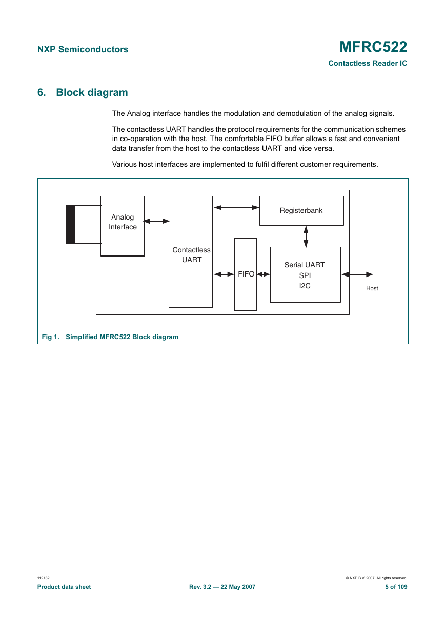
NXP Semiconductors 6. Block diagram MFRC522 Contactless Reader IC The Analog interface handles the modulation and demodulation of the analog signals. The contactless UART handles the protocol requirements for the communication schemes in co-operation with the host. The comfortable FIFO buffer allows a fast and convenient data transfer from the host to the contactless UART and vice versa. Various host interfaces are implemented to fulfil different customer requirements. Analog Interface Registerbank Contactless UART FIFO Serial UART SPI I2C Host Fig 1. Simplified MFRC522 Block diagram 112132 Product data sheet Rev. 3.2 — 22 May 2007 © NXP B.V. 2007. All rights reserved. 5 of 109
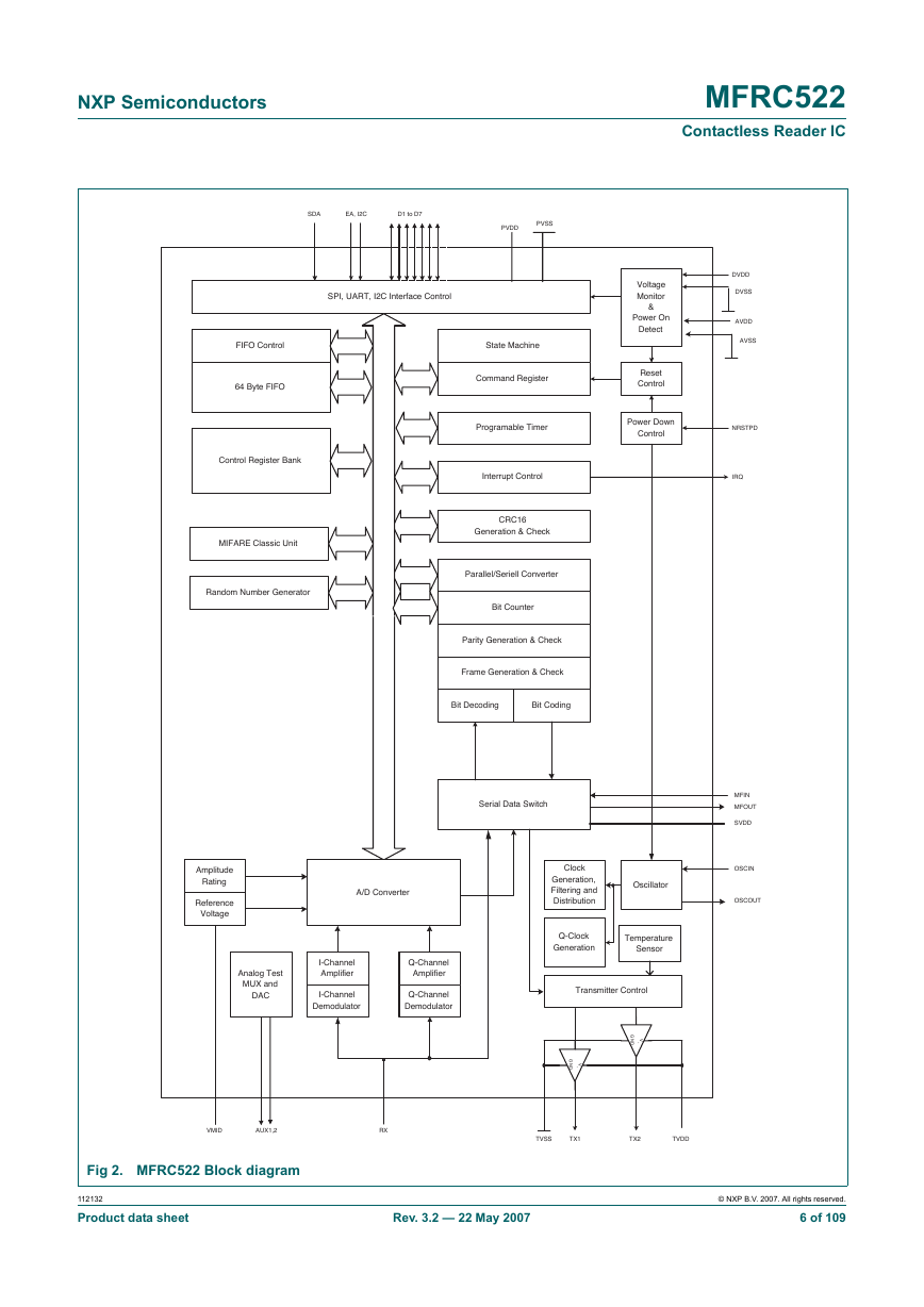
NXP Semiconductors MFRC522 Contactless Reader IC Voltage Monitor & Power On Detect Reset Control Power Down Control SDA EA, I2C D1 to D7 PVDD PVSS SPI, UART, I2C Interface Control FIFO Control 64 Byte FIFO Control Register Bank MIFARE Classic Unit Random Number Generator State Machine Command Register Programable Timer Interrupt Control CRC16 Generation & Check Parallel/Seriell Converter Bit Counter Parity Generation & Check Frame Generation & Check Bit Decoding Bit Coding Serial Data Switch Amplitude Rating Reference Voltage A/D Converter Analog Test MUX and DAC I-Channel Amplifier I-Channel Demodulator Q-Channel Amplifier Q-Channel Demodulator Clock Generation, Filtering and Distribution Oscillator Q-Clock Generation Temperature Sensor Transmitter Control G N D V + G N D V + DVDD DVSS AVDD AVSS NRSTPD IRQ MFIN MFOUT SVDD OSCIN OSCOUT VMID AUX1,2 RX TVSS TX1 TX2 TVDD Fig 2. MFRC522 Block diagram 112132 Product data sheet Rev. 3.2 — 22 May 2007 © NXP B.V. 2007. All rights reserved. 6 of 109
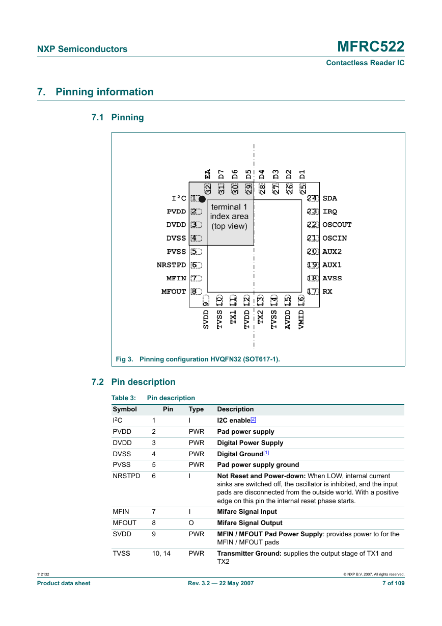
NXP Semiconductors 7. Pinning information 7.1 Pinning MFRC522 Contactless Reader IC Fig 3. Pinning configuration HVQFN32 (SOT617-1). 7.2 Pin description Table 3: Symbol I2C PVDD DVDD DVSS PVSS NRSTPD MFIN MFOUT SVDD Pin description Pin 1 2 3 4 5 6 7 8 9 Type I PWR PWR PWR PWR I I O PWR TVSS 10, 14 PWR Description I2C enable[2] Pad power supply Digital Power Supply Digital Ground[1] Pad power supply ground Not Reset and Power-down: When LOW, internal current sinks are switched off, the oscillator is inhibited, and the input pads are disconnected from the outside world. With a positive edge on this pin the internal reset phase starts. Mifare Signal Input Mifare Signal Output MFIN / MFOUT Pad Power Supply: provides power to for the MFIN / MFOUT pads Transmitter Ground: supplies the output stage of TX1 and TX2 112132 Product data sheet Rev. 3.2 — 22 May 2007 © NXP B.V. 2007. All rights reserved. 7 of 109
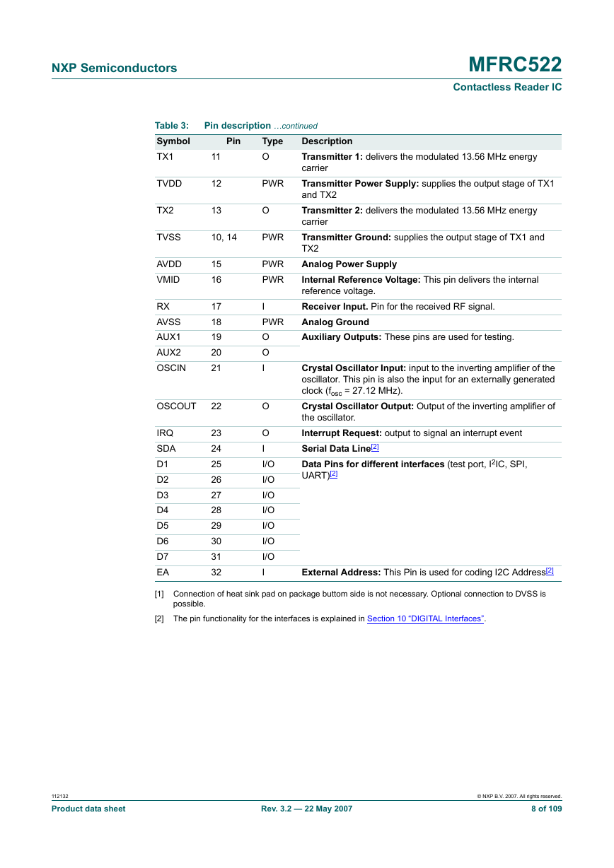
NXP Semiconductors MFRC522 Contactless Reader IC Pin description …continued Description Transmitter 1: delivers the modulated 13.56 MHz energy carrier Transmitter Power Supply: supplies the output stage of TX1 and TX2 Transmitter 2: delivers the modulated 13.56 MHz energy carrier Transmitter Ground: supplies the output stage of TX1 and TX2 Analog Power Supply Internal Reference Voltage: This pin delivers the internal reference voltage. Receiver Input. Pin for the received RF signal. Analog Ground Auxiliary Outputs: These pins are used for testing. Crystal Oscillator Input: input to the inverting amplifier of the oscillator. This pin is also the input for an externally generated clock (fosc = 27.12 MHz). Crystal Oscillator Output: Output of the inverting amplifier of the oscillator. Interrupt Request: output to signal an interrupt event Serial Data Line[2] Data Pins for different interfaces (test port, I2IC, SPI, UART)[2] External Address: This Pin is used for coding I2C Address[2] Table 3: Symbol TX1 TVDD TX2 Pin 11 12 13 Type O PWR O TVSS 10, 14 PWR AVDD VMID RX AVSS AUX1 AUX2 OSCIN OSCOUT IRQ SDA D1 D2 D3 D4 D5 D6 D7 EA 15 16 17 18 19 20 21 22 23 24 25 26 27 28 29 30 31 32 PWR PWR I PWR O O I O O I I/O I/O I/O I/O I/O I/O I/O I [1] Connection of heat sink pad on package buttom side is not necessary. Optional connection to DVSS is possible. [2] The pin functionality for the interfaces is explained in Section 10 “DIGITAL Interfaces”. 112132 Product data sheet Rev. 3.2 — 22 May 2007 © NXP B.V. 2007. All rights reserved. 8 of 109
分享到:
收藏