LGDP4535
Rev 0.12
LGDP4535
720-Channel, 262,144-Color One-Chip Driver
with RAM, Power Supply and Gate Circuits
for Amorphous TFT-LCD Panels
Rev 0.12
2008-02-26
Description ................................................................................................................................................... 4
Features ........................................................................................................................................................ 5
Block Diagram ............................................................................................................................................. 6
Pin Function ................................................................................................................................................. 7
PAD Arrangement ..................................................................................................................................... 12
PAD Coordinate ........................................................................................................................................ 13
Bump Arrangement .................................................................................................................................... 27
Block Function ........................................................................................................................................... 28
System Interface .................................................................................................................................... 28
External Display Interface ..................................................................................................................... 28
Address Counter (AC) ........................................................................................................................... 29
Graphics RAM (GRAM) ....................................................................................................................... 29
Grayscale Voltage Generating Circuit ................................................................................................... 29
Timing Generator .................................................................................................................................. 29
Oscillator (OSC) .................................................................................................................................... 29
LCD Driver Circuit ................................................................................................................................ 29
LCD Drive Power Supply Circuit .......................................................................................................... 29
Internal logic power supply regulator .................................................................................................... 29
GRAM Address MAP ................................................................................................................................ 30
Instructions ................................................................................................................................................. 38
Outline ................................................................................................................................................... 38
Instruction Data Format ......................................................................................................................... 38
Instruction Description .......................................................................................................................... 40
Index (IR) .............................................................................................................................................. 40
Device code read (R00h) ....................................................................................................................... 40
Driver output control (R01h) ................................................................................................................. 40
LCD Driving Wave Control (R02h) ...................................................................................................... 40
Entry Mode (R03h) ................................................................................................................................ 41
Resizing Control (R04h) ........................................................................................................................ 44
Display Control 1 (R07h) ...................................................................................................................... 45
Display Control 2 (R08h) ...................................................................................................................... 46
Display Control 3 (R09h) ...................................................................................................................... 47
Display Control 4 (R0Ah) ..................................................................................................................... 49
External Display Interface Control 1 (R0Ch) ........................................................................................ 49
Frame Marker Position (R0Dh) ............................................................................................................. 51
External Display Interface Control 2 (R0Fh) ......................................................................................... 52
Power Control 1 (R10h) ......................................................................................................................... 52
Power Control 2 (R11h) ......................................................................................................................... 55
Power Control 3 (R12h) ......................................................................................................................... 56
Power Control 4 (R13h) ......................................................................................................................... 56
Regulator Control (R15h) ..................................................................................................................... 58
Gamma Select Control (R16h) .............................................................................................................. 59
Vcom Control (R17h) ............................................................................................................................ 60
1
�
LGDP4535
Rev 0.12
RAM Address Set (Horizontal Address) (R20h) ................................................................................... 61
RAM Address Set (Vertical Address) (R21h) ....................................................................................... 61
Write Data to RAM (R22h) .................................................................................................................. 61
Read Data from RAM (R22h) ............................................................................................................... 64
Gamma Control 1-16 (R30h to R3Fh) ................................................................................................... 65
EPROM Control Register 1 (R40h) ....................................................................................................... 66
EPROM Control Register 2 (R41h) ....................................................................................................... 66
EPROM Control Register 3 (R42h) ....................................................................................................... 67
Window Horizontal RAM Address Start/End (R50h/R51h) ................................................................. 67
Window Vertical RAM Address Start/End (R52h/R53h) ...................................................................... 67
Driver Output Control (R60h) ............................................................................................................... 68
Base Image Display Control (R61h) ...................................................................................................... 68
Vertical Scroll Control (R6Ah).............................................................................................................. 68
Software Reset (R70h) ........................................................................................................................... 71
I/F Endian Control (R71h) ..................................................................................................................... 71
Memory Write Control (R72h) .............................................................................................................. 71
Partial Image 1: Display Position (R80h) .............................................................................................. 72
RAM Address (Start/End Line Address) (R81h/R82h) ......................................................................... 72
Partial Image 2: Display Position (R83h) .............................................................................................. 72
RAM Address (Start/End Line Address) (R84h/R85h) ......................................................................... 72
Panel Interface Control 1 (R90h) ........................................................................................................... 72
Panel Interface Control 2 (R92h) ........................................................................................................... 73
Panel Interface Control 3 (R93h) ........................................................................................................... 74
Panel Interface Control 4 (R95h) ........................................................................................................... 75
Panel Interface Control 5 (R97h) ........................................................................................................... 76
Panel Interface Control 6 (R98h) ........................................................................................................... 76
Frame Rate Control (R9Ah) .................................................................................................................. 77
Test Register 1 (RA0h) .......................................................................................................................... 78
Test Register 2 (RA1h) .......................................................................................................................... 78
Test Register 3 (RA2h) .......................................................................................................................... 78
Test Register 4 (RA3h) .......................................................................................................................... 79
Test Register 5 (RA4h) .......................................................................................................................... 79
Test Register 6 (RA5h) .......................................................................................................................... 79
Instruction List ........................................................................................................................................... 80
Reset Function ............................................................................................................................................ 82
Basic Mode operation of the LGDP4535 ................................................................................................... 84
Interface and data format ............................................................................................................................ 85
System Interface ......................................................................................................................................... 87
80-system 18-bit Bus Interface .............................................................................................................. 88
80-system 16-bit Bus Interface .............................................................................................................. 89
Data Transfer Synchronous in 16-bit Bus Interface operation ............................................................... 90
80-system 9-bit Bus Interface ................................................................................................................ 91
Data Transfer Synchronous in 9-bit Bus Interface operation ................................................................. 92
80-system 8-bit Bus Interface ................................................................................................................ 92
Data Transfer Synchronous in 8-bit Bus Interface operation ................................................................. 94
Serial Interface ....................................................................................................................................... 95
VSYNC Interface ....................................................................................................................................... 98
Notes in using the VSYNC interface ................................................................................................... 100
External Display Interface ........................................................................................................................ 102
RGB Interface ...................................................................................................................................... 102
Polarities of VSYNC, HSYNC, ENABLE, and DOTCLK Signals ..................................................... 103
RGB Interface Timing ......................................................................................................................... 103
Moving Picture Display with the RGB Interface ................................................................................. 104
RAM access via system interface in RGB interface operation ............................................................ 105
6-bit RGB Interface ............................................................................................................................. 106
Data Transfer Synchronization in 6-bit Bus Interface operation ......................................................... 107
16-bit RGB Interface ........................................................................................................................... 108
2
�
LGDP4535
Rev 0.12
18-bit RGB Interface ........................................................................................................................... 109
Notes on Using the External Display Interface .................................................................................... 110
RAM Address and Display Position on the Panel .................................................................................... 112
Restrictions in setting display control instruction ................................................................................ 113
Screen setting ....................................................................................................................................... 113
Instruction setting example .................................................................................................................. 114
Resizing function ...................................................................................................................................... 117
Resizing setting .................................................................................................................................... 118
Notes to Resizing function ................................................................................................................... 118
FMARK function ..................................................................................................................................... 120
FMP setting example ........................................................................................................................... 121
Display operation synchronous data transfer using FMARK .............................................................. 121
Window Address Function ....................................................................................................................... 123
EPROM Control ....................................................................................................................................... 124
Scan Mode Setting .................................................................................................................................... 126
Line Inversion AC Drive .......................................................................................................................... 127
Frame-Frequency Adjustment Function ................................................................................................... 128
Relationship between the liquid crystal Drive Duty and the Frame Frequency ................................... 128
Partial Display Function ........................................................................................................................... 129
Liquid crystal panel interface timing ........................................................................................................ 130
Internal clock operation ....................................................................................................................... 130
RGB Interface operation ...................................................................................................................... 131
γ-Correction Function ............................................................................................................................... 132
Grayscale Amplifier Unit Configuration ............................................................................................. 133
γ-Correction Register ........................................................................................................................... 135
Ladder Resistors and 8-to-1 Selector ................................................................................................... 136
8-Color Display Mode .............................................................................................................................. 141
Power-supply Generating Circuit ............................................................................................................. 143
Power supply circuit connection example 1 (Vci1 = VciOUT) ........................................................... 143
Power supply circuit connection example2 (Vci1 = Vci direct input) ................................................. 144
Specifications of Power-supply Circuit External Elements ...................................................................... 145
Voltage Setting Pattern Diagram .............................................................................................................. 146
Power Supply Instruction Setting ............................................................................................................. 147
Instruction Setting .................................................................................................................................... 148
Display ON/OFF sequence .................................................................................................................. 148
Standby / Sleep mode SET/EXIT sequences ....................................................................................... 149
Deep standby mode IN/EXIT sequences ............................................................................................ 150
8-color mode setting ............................................................................................................................ 150
Parital Display setting .......................................................................................................................... 151
Absolute Maximum Ratings ..................................................................................................................... 152
Electrical Characteristics .......................................................................................................................... 153
DC Characteristics ............................................................................................................................... 153
80-System Bus Interface Timing Characteristics (18/16-Bit Bus)....................................................... 153
80-System Bus Interface Timing Characteristics (8/9-Bit Bus) .......................................................... 154
Serial Peripheral Interface Timing Characteristics ............................................................................. 154
RGB Interface Timing Characteristics................................................................................................. 155
Reset Timing Characteristics ............................................................................................................... 155
Notes to Electrical Characteristics ....................................................................................................... 156
Timing characteristic diagram ............................................................................................................. 157
3
�
LGDP4535
Rev 0.12
Description
The LGDP4535 is a one-chip liquid crystal controller driver LSI, comprising RAM of 240 RGB x 320
dots at maximum, a source driver, a gate driver and a power supply circuit. For effective data transfer, the
LGDP4535 supports high-speed 8-/9-/16-/18-bit bus interfaces as a system interface to microcomputer
and high-speed RAM write mode.
As a moving picture interface, the LGDP4535 supports RGB interface (VSYNC, HSYNC, DOTCLK,
ENABLE, DB17-0).
Also, the LGDP4535 incorporates step-up circuits and voltage follower circuits to generate TFT liquid
crystal panel drive voltages.
The LGDP4535’s power management functions such as 8-color display and deep standby and so on make
this LSI an ideal driver for the medium or small sized portable products with color display systems such
as digital cellular phones or small PDAs, where long battery life is a major concern.
4
�
LGDP4535
Rev 0.12
Features
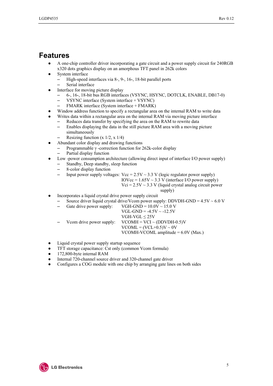
● A one-chip controller driver incorporating a gate circuit and a power supply circuit for 240RGB
●
●
Serial interface
x320 dots graphics display on an amorphous TFT panel in 262k colors
System interface
– High-speed interfaces via 8-, 9-, 16-, 18-bit parallel ports
–
Interface for moving picture display
–
– VSYNC interface (System interface + VSYNC)
–
FMARK interface (System interface + FMARK)
6-, 16-, 18-bit bus RGB interfaces (VSYNC, HSYNC, DOTCLK, ENABLE, DB17-0)
● Window address function to specify a rectangular area on the internal RAM to write data
● Writes data within a rectangular area on the internal RAM via moving picture interface
– Reduces data transfer by specifying the area on the RAM to rewrite data
– Enables displaying the data in the still picture RAM area with a moving picture
simultaneously
– Resizing function (x 1/2, x 1/4)
● Abundant color display and drawing functions
Programmable γ -correction function for 262k-color display
Partial display function
● Low -power consumption architecture (allowing direct input of interface I/O power supply)
Standby, Deep standby, sleep function
8-color display function
Input power supply voltages: Vcc = 2.5V ~ 3.3 V (logic regulator power supply)
–
–
–
–
–
IOVcc = 1.65V ~ 3.3 V (interface I/O power supply)
Vci = 2.5V ~ 3.3 V (liquid crystal analog circuit power
supply)
Source driver liquid crystal drive/Vcom power supply: DDVDH-GND = 4.5V ~ 6.0 V
●
Incorporates a liquid crystal drive power supply circuit
–
– Gate drive power supply: VGH-GND = 10.0V ~ 15.0 V
VGL-GND = -4.5V ~ -12.5V
VGH-VGL ≤ 25V
– Vcom drive power supply: VCOMH = VCI ~ (DDVDH-0.5)V
VCOML = (VCL+0.5)V ~ 0V
VCOMH-VCOML amplitude = 6.0V (Max.)
● Liquid crystal power supply startup sequence
● TFT storage capacitance: Cst only (common Vcom formula)
●
●
● Configures a COG module with one chip by arranging gate lines on both sides
172,800-byte internal RAM
Internal 720-channel source driver and 320-channel gate driver
5
�
LGDP4535
Rev 0.12
Block Diagram
Index
Register (IR)
Control
Register
(CR)
Address
counter
BGR circuit
18
Write data
latch
18
Graphic RAM
(GRAM)
18
Read data
latch
18
172,800 bytes
V63-V0
Timing
genrator
IM2-1, IM0/ID
CS*
RS
WR/SCL
RD*
SDI
SDO
DB017-0
System
Interface
18-bit
16-bit
9-bit
8-bit
8-bit serial
External display
Interface
DB17-0
VSYNC
HSYNC
DOTCLK
ENABLE
CPG
Internal reference
voltage
generating circuit
Internal logic
power supply
regulator
VSYNC
HSYNC
DOTCLK
ENABLE
FMARK
RESET*
VCC
VDD
Liquid crystal drive level generating circuit
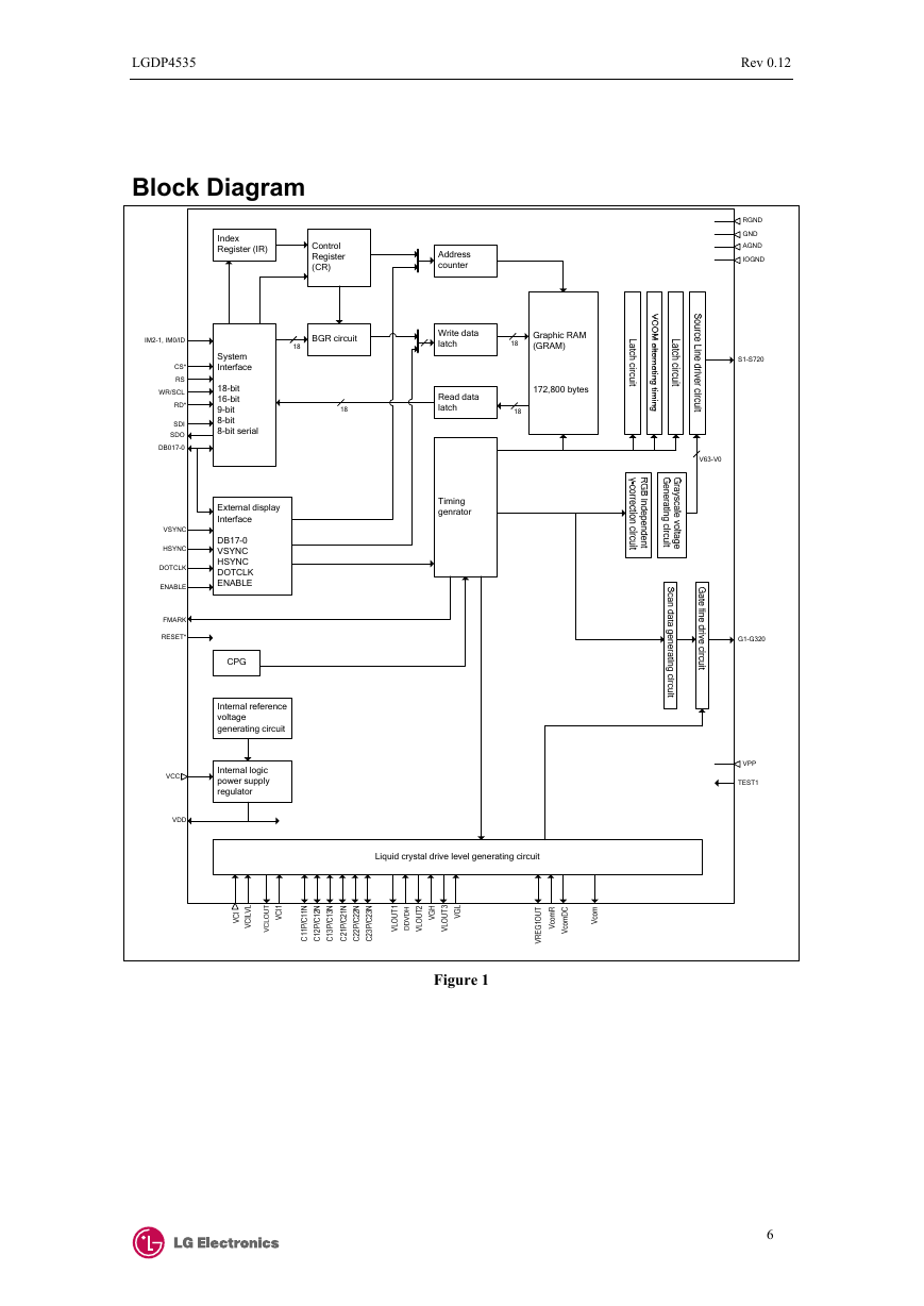
Figure 1
RGND
GND
AGND
IOGND
S1-S720
G1-G320
VPP
TEST1
6
�
LGDP4535
Rev 0.12
Pin Function
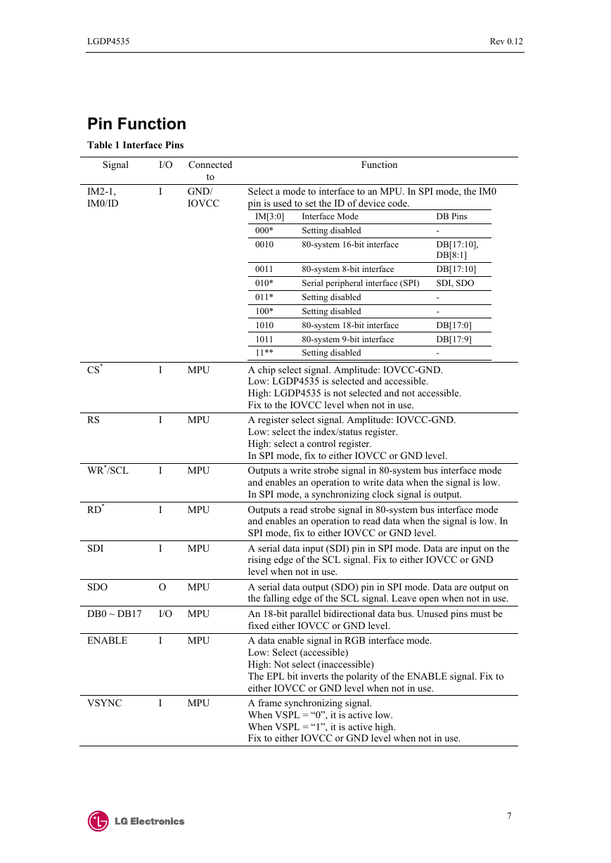
Table 1 Interface Pins
Signal
IM2-1,
IM0/ID
CS*
RS
WR*/SCL
RD*
SDI
I
I
I
I
I
I
I/O Connected
to
GND/
IOVCC
MPU
MPU
MPU
MPU
MPU
SDO
O
MPU
DB0 ~ DB17
I/O MPU
ENABLE
VSYNC
I
I
MPU
MPU
Function
Select a mode to interface to an MPU. In SPI mode, the IM0
pin is used to set the ID of device code.
IM[3:0]
000*
0010
Interface Mode
Setting disabled
80-system 16-bit interface
0011
010*
011*
100*
1010
1011
11**
80-system 8-bit interface
Serial peripheral interface (SPI)
Setting disabled
Setting disabled
80-system 18-bit interface
80-system 9-bit interface
Setting disabled
DB Pins
-
DB[17:10],
DB[8:1]
DB[17:10]
SDI, SDO
-
-
DB[17:0]
DB[17:9]
-
A chip select signal. Amplitude: IOVCC-GND.
Low: LGDP4535 is selected and accessible.
High: LGDP4535 is not selected and not accessible.
Fix to the IOVCC level when not in use.
A register select signal. Amplitude: IOVCC-GND.
Low: select the index/status register.
High: select a control register.
In SPI mode, fix to either IOVCC or GND level.
Outputs a write strobe signal in 80-system bus interface mode
and enables an operation to write data when the signal is low.
In SPI mode, a synchronizing clock signal is output.
Outputs a read strobe signal in 80-system bus interface mode
and enables an operation to read data when the signal is low. In
SPI mode, fix to either IOVCC or GND level.
A serial data input (SDI) pin in SPI mode. Data are input on the
rising edge of the SCL signal. Fix to either IOVCC or GND
level when not in use.
A serial data output (SDO) pin in SPI mode. Data are output on
the falling edge of the SCL signal. Leave open when not in use.
An 18-bit parallel bidirectional data bus. Unused pins must be
fixed either IOVCC or GND level.
A data enable signal in RGB interface mode.
Low: Select (accessible)
High: Not select (inaccessible)
The EPL bit inverts the polarity of the ENABLE signal. Fix to
either IOVCC or GND level when not in use.
A frame synchronizing signal.
When VSPL = “0”, it is active low.
When VSPL = “1”, it is active high.
Fix to either IOVCC or GND level when not in use.
7
�
LGDP4535
Rev 0.12
HSYNC
DOTCLK
RESET*
I
I
I
FMARK
O
MPU
MPU
MPU or
External
RC circuit
MPU
A line synchronizing signal.
When HSPL = “0”, it is active low.
When HSPL = “1”, it is active high.
Fix to either IOVCC or GND level when not in use.
A dot clock signal.
When DPL = “0”, input data on the rising edge of DOTCLK.
When DPL = “1”, input data on the falling edge of DOTCLK.
Fix to either IOVCC or GND level when not in use.
A reset pin.
Initializes the LGDP4535 with a low input. Be sure to execute a
power-on reset after supplying power.
Frame head pulse signal, which is used when writing data to the
internal GRAM. Leave open when not in use.
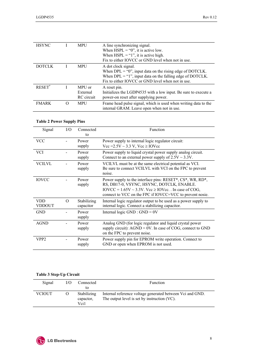
Table 2 Power Supply Pins
I/O Connected
Signal
VCC
VCI
VCILVL
IOVCC
VDD
VDDOUT
GND
AGND
VPP2
-
-
-
-
O
-
-
-
to
Power
supply
Power
supply
Power
supply
Power
supply
Stabilizing
capacitor
Power
supply
Power
supply
Power
supply
Function
Power supply to internal logic regulator circuit:
Vcc =2.5V ~ 3.3 V, Vcc ≥ IOVcc
Power supply to liquid crystal power supply analog circuit.
Connect to an external power supply of 2.5V ~ 3.3V.
VCILVL must be at the same electrical potential as VCI.
Be sure to connect VCILVL with VCI on the FPC to prevent
noise.
Power supply to the interface pins: RESET*, CS*, WR, RD*,
RS, DB17-0, VSYNC, HSYNC, DOTCLK, ENABLE.
IOVCC = 1.65V ~ 3.3V. Vcc ≥ IOVcc. . In case of COG,
connect to VCC on the FPC if IOVCC=VCC to prevent nosie.
Internal logic regulator output to be used as a power supply to
internal logic. Connect a stabilizing capacitor.
Internal logic GND : GND = 0V
Analog GND (for logic regulator and liquid crystal power
supply circuit): AGND = 0V. In case of COG, connect to GND
on the FPC to prevent noise.
Power supply pin for EPROM write operation. Connect to
GND or open when EPROM is not used.
Function
Internal reference voltage generated between Vci and GND.
The output level is set by instruction (VC).
Table 3 Step-Up Circuit
Signal
I/O Connected
to
VCIOUT
O
Stabilizing
capactor,
Vci1
8
�
