Draft Version NNTT3355331100
NNTT3355331100
One-chip Driver IC with internal GRAM for 262K colors
320RGB x 480 a-Si TFT LCD with CPU / RGB / MDDI / MIPI
Interface
Draft Version
Version 0.02
2012/02/09
2012/02/09 1 Version 0.02
With respect to the information represented in this document, NOVATEK makes no warranty, expressed or implied, including the warranties of
merchantability, fitness for a particular purpose, and non-infringement, nor assumes any legal liability or responsibility for the accuracy,
completeness or usefulness of any such information.
�
Draft Version NNTT3355331100
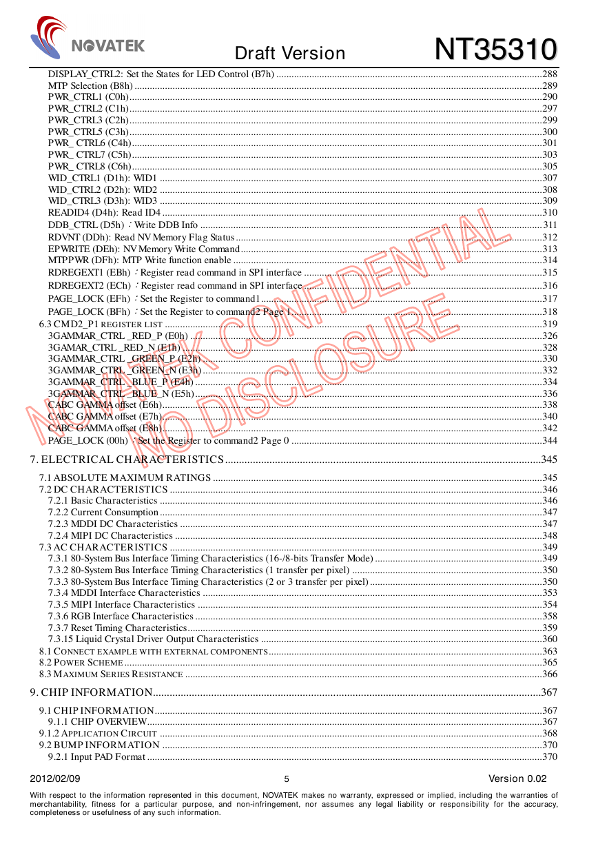
INDEX
REVERSION HISTORY.................................................................................................................................................7
1. GENERAL DESCRIPTION .......................................................................................................................................8
1.1 PURPOSE OF THIS DOCUMENT ...................................................................................................................................................8
1.2 GENERAL DESCRIPTION.............................................................................................................................................................8
2. FEATURES...................................................................................................................................................................9
3. BLOCK DIAGRAM ..................................................................................................................................................12
4. PIN DESCRIPTIONS................................................................................................................................................13
4.1 POWER INPUTS .........................................................................................................................................................................13
4.2 MCU SYSTEM INTERFACE.......................................................................................................................................................13
4.3 SPI INTERFACE.........................................................................................................................................................................14
4.4 RGB INTERFACE ......................................................................................................................................................................14
4.5 MDDI / MIPI INTERFACE........................................................................................................................................................15
4.6 CABC CONTROL PINS .............................................................................................................................................................15
4.7 INTERFACE LOGIC PINS ...........................................................................................................................................................16
4.8 DISPLAY DRIVER ANALOG OUTPUTS ......................................................................................................................................17
4.9 POWER SUPPLY ........................................................................................................................................................................18
4.10 TEST PINS (TEST AND DUMMY PINS) .....................................................................................................................................18
5. FUNCTION DESCRIPTIONS..................................................................................................................................19
5.1 MPU INTERFACE......................................................................................................................................................................19
5.1.1 General Protocol................................................................................................................................................................20
5.1.2 80-System Interface............................................................................................................................................................20
5.1.2.1 Write cycle sequence......................................................................................................................................................................... 21
5.1.2.2 Read Cycle Sequence........................................................................................................................................................................ 22
5.2 SPI INTERFACE.........................................................................................................................................................................23
5.2.1 General Description for LoSSI...........................................................................................................................................23
5.2.2 Command Write for LoSSI..................................................................................................................................................23
5.2.3 Read Functions for LoSSI ..................................................................................................................................................23
5.2.4 Display Module Data Transfer Recovery for LoSSI...........................................................................................................24
5.2.5 Display Module Data Transfer Pause for LoSSI ................................................................................................................26
5.2.6 Display Module Data Transfer Modes for LoSSI ...............................................................................................................27
5.2.6.1 Method 1........................................................................................................................................................................................... 27
5.2.6.2 Method 2........................................................................................................................................................................................... 27
5.3 DISPLAY DATA RAM (DDRAM)...............................................................................................................................................28
5.3.1 Serial Interface for DATA RAM write ................................................................................................................................29
5.3.2 8-Bits Parallel Interface for RAM Data Write....................................................................................................................30
5.3.3 9-Bits Parallel Interface (80-system) for RAM Data Write ................................................................................................32
5.3.4 16-Bits Parallel Interface for RAM Data Write..................................................................................................................33
5.3.5 18-Bits Parallel Interface for RAM Data Write..................................................................................................................35
5.3.6 Serial Interface Signals for RAM Data Read .....................................................................................................................36
5.3.7 80-8-bits Parallel Interface Signals for RAM Data Read ..................................................................................................37
5.3.8 80-9-bits Parallel Interface Signals for RAM Data Read ..................................................................................................38
5.3.9 80-16-bits Parallel Interface Signals for RAM Data Read ................................................................................................39
5.3.10 80-18-bits Parallel Interface Signals for RAM Data Read..............................................................................................40
5.4 RGB INTERFACE ......................................................................................................................................................................41
5.4.1 General Description...........................................................................................................................................................41
5.4.2 General Timing Diagram ...................................................................................................................................................42
5.4.3 RGB Interface Bus Width Set..............................................................................................................................................43
5.4.4 RGB Interface Mode Set.....................................................................................................................................................44
5.4.5 RGB Interface Mode 1 & Mode 2 Timing Chart ................................................................................................................45
5.5 FRAME TEARING EFFECT INTERFACE.....................................................................................................................................48
5.5.1 Tearing Effect Line Modes..................................................................................................................................................48
5.5.2 Example 1: MPU write is faster than panel read...............................................................................................................51
5.5.3 Example 2: MPU write is slower than panel read .............................................................................................................52
5.6 MDDI INTERFACE (MOBILE DISPLAY DIGITAL INTERFACE) .................................................................................................56
2012/02/09 2 Version 0.02
With respect to the information represented in this document, NOVATEK makes no warranty, expressed or implied, including the warranties of
merchantability, fitness for a particular purpose, and non-infringement, nor assumes any legal liability or responsibility for the accuracy,
completeness or usefulness of any such information.
�
Draft Version NNTT3355331100
5.6.1 MDDI Link Protocol ..........................................................................................................................................................57
5.6.2 MDDI Link Packet descriptions.........................................................................................................................................57
5.6.3 Writing Video Data to Memory Sequence...........................................................................................................................67
5.6.4 Writing Register Sequence..................................................................................................................................................67
5.6.5 Reading Video Data from Memory Sequence .....................................................................................................................68
5.6.6 Reading Register Sequence ................................................................................................................................................68
5.6.7 Hibernation Setting ............................................................................................................................................................69
5.6.8 Deep Standby Mode Setting by MDDI ...............................................................................................................................70
5.6.9 Vsync Based Link Wakeup ..................................................................................................................................................72
5.7 MIPI INTERFACE (MOBILE INDUSTRY PROCESSING INTERFACE) .........................................................................................73
5.7.1 Display Module Pin Configuration for DSI .......................................................................................................................74
5.7.2 Display Serial Interface (DSI)............................................................................................................................................75
5.7.2.1 General Description ......................................................................................................................................................................... 75
5.7.2.2 Interface Level Communication........................................................................................................................................................ 75
5.7.2.2.1 General...................................................................................................................................................................................... 75
5.7.2.2.2 DSI-CLOCK Lane ..................................................................................................................................................................... 76
5.7.2.2.3 DSI-DATA Lanes........................................................................................................................................................................ 82
5.7.2.3 Packet Level Communication ........................................................................................................................................................... 93
5.7.2.3.1 Short Packet (SPa) and Long Packet (LPa) Structures.............................................................................................................. 93
5.7.2.3.2 Packer Transmission................................................................................................................................................................ 112
5.7.2.3.3 Communication Sequence........................................................................................................................................................ 143
5.7.2.4 Video Mode Communication........................................................................................................................................................... 155
5.7.2.4.1 Transmission Packet Sequences............................................................................................................................................... 155
5.7.2.4.2 Non-Burst Mode with Sync Pulses........................................................................................................................................... 156
5.7.2.4.3 Non-Burst Mode with Sync Events........................................................................................................................................... 157
5.7.2.4.4 Burst Mode .............................................................................................................................................................................. 158
5.7.2.4.5 Parameters .............................................................................................................................................................................. 158
5.7.2.4.6 Video mode ON/OFF sequence................................................................................................................................................ 159
5.7.3 Memory access for DSI ....................................................................................................................................................161
5.8 WINDOW ADDRESS FUNCTION...............................................................................................................................................169
5.9 REDUCED POWER CONSUMPTION DRIVE SETTINGS.............................................................................................................170
5.10 FRAME-FREQUENCY ADJUSTMENT FUNCTION ...................................................................................................................170
5.11 GAMMA FUNCTION ............................................................................................................................................................171
5.12 RESET FUNCTION .................................................................................................................................................................172
5.13 BASIC OPERATION MODE ....................................................................................................................................................174
5.14 POWER ON/OFF SEQUENCE .................................................................................................................................................175
5.15 INSTRUCTION SETTING SEQUENCE......................................................................................................................................176
5.15.1 Sleep SET/EXIT Sequences ............................................................................................................................................176
5.15.2 Deep Standby Mode ENTER/EXIT Sequences ...............................................................................................................177
5.16 MTP WRITE SEQUENCE.......................................................................................................................................................178
5.16.1 First Time MTP Programming Sequence (for all MTP).................................................................................................179
5.16.2 Second Time MTP Programming Sequence...................................................................................................................180
5.16.3 Third Time MTP Programming Sequence (Only for VCOM, ID and WRDDB) .............................................................181
5.16.4 Fourth Time MTP Programming Sequence (Only for VCOM, ID and WRDDB)...........................................................182
5.17 INSTRUCTION SETUP FLOW .................................................................................................................................................183
5.17.1 Initializing with the Build-in Power Supply Circuit .......................................................................................................183
5.17.2 Power Off Sequence .......................................................................................................................................................184
5.18 SLEEP OUT–COMMAND AND SELF-DIAGNOSTIC FUNCTIONS OF THE DISPLAY MODULE......................185
6. COMMAND DESCRIPTIONS...............................................................................................................................187
6.1 USER COMMAND SET (COMMAND 1).....................................................................................................................................189
NOP (00h): No Operation ........................................................................................................................................................191
SOFT_RESET (01h): Software Reset ........................................................................................................................................192
RDID (04h): Read Display ID ..................................................................................................................................................193
RDNUMED (05h): Read Number of the Errors on DSI ...........................................................................................................194
GET_POWER_MODE (0Ah): Read Display Power Mode ......................................................................................................195
GET_ADDRESS_MODE (0Bh): Get the Frame Memory to the Display Panel Read Order....................................................196
GET_PIXEL_MODE (0Ch): Read Input Pixel Format.............................................................................................................197
GET_DISPLAY_MODE (0Dh): Read the Current Display Mode.............................................................................................198
GET_SIGNAL_MODE (0Eh): Get Display Module Signaling Mode .......................................................................................199
RDDSDR (0Fh): Read Display Self-Diagnostic Result.............................................................................................................200
ENTER_SLEEP_MODE (10h): Enter the Sleep-In Mode.........................................................................................................201
2012/02/09 3 Version 0.02
With respect to the information represented in this document, NOVATEK makes no warranty, expressed or implied, including the warranties of
merchantability, fitness for a particular purpose, and non-infringement, nor assumes any legal liability or responsibility for the accuracy,
completeness or usefulness of any such information.
�
Draft Version NNTT3355331100
EXIT_SLEEP_MODE (11h): Exit the Sleep-In Mode ...............................................................................................................202
ENTER_PARTIAL_MODE (12h): Partial Display Mode On ...................................................................................................203
ENTER_NORMAL_MODE (13h): Normal Display Mode On .................................................................................................204
EXIT_INVERT_MODE (20h): Display Inversion Off...............................................................................................................205
ENTER_INVERT_MODE (21h): Display Inversion On...........................................................................................................206
ALLPOFF (22h): All Pixel Off..................................................................................................................................................207
ALLPON (23h): All Pixel On ....................................................................................................................................................208
GMASET (26h): Gamma Curves Selection ...............................................................................................................................209
SET_DISPLAY_OFF (28h): Display Off ..................................................................................................................................210
SET_DISPLAY_ON (29h): Display On..................................................................................................................................... 211
SET_HORIZONTAL_ADDRESS (2Ah): Set the Column Address .............................................................................................212
SET_VERTICAL_ADDRESS (2Bh): Set Page Address.............................................................................................................214
WRITE_MEMORY_START (2Ch): Memory Write Start Command ..........................................................................................216
SET_MDDI_RAM_READ_ADDRESS (2Dh): Set the RAM Horizontal and Vertical Address..................................................217
READ_MEMORY_START (2Eh): Memory Read Start Command ............................................................................................218
SET_PARTIAL_AREA (30h): Defines the Partial Display Area ...............................................................................................220
SCRLAR (33h): Set Scroll Area.................................................................................................................................................222
SET_TEAR_ON (35h): Tearing Effect Line ON ........................................................................................................................226
SET_ADDRESS_MODE (36h): Memory Data Access Control ................................................................................................228
VSCSAD (37h): Vertical Scroll Start Address of RAM ..............................................................................................................231
EXIT_IDLE_MODE (38h): Idle Mode Off ...............................................................................................................................233
ENTER_IDLE_MODE (39h): Idle Mode On ............................................................................................................................234
SET_PIXEL_FORMAT (3Ah): Set the Interface Pixel Format .................................................................................................236
RGBCTRL (3Bh): RGB Interface Signal Control......................................................................................................................237
RAMWRC (3Ch): Memory Write Continuously ........................................................................................................................240
RAMRDC (3Eh):RAM Read Continuously.............................................................................................................................241
SET_TEAR_SCANLINE (44h): Set Tear Line ...........................................................................................................................242
RDSCL (45h):Read Scan Line................................................................................................................................................244
ENTER_DSTB_MODE (4Fh): Enter the Deep Standby Mode .................................................................................................245
WRDISBV (51h): Write Display Brightness ..............................................................................................................................246
RDDISBV (52h): Read Display Brightness...............................................................................................................................247
WRCTRLD (53h): Write CTRL Display ....................................................................................................................................248
RDCTRLD (54h): Read CTRL Display .....................................................................................................................................250
WRCTRLD (55h): Write CTRL Display ....................................................................................................................................251
RDCABC (56h): Read Content Adaptive Brightness Control (CABC) Mode ...........................................................................252
RDCABCMB (5Fh): Read CABC Minimum Brightness ...........................................................................................................254
RDDSDR (68h): Read Display Self-Diagnostic Result.............................................................................................................255
SET_MDDI (8Fh) .....................................................................................................................................................................256
RDDDBS (A1h): Read DDB Start.............................................................................................................................................257
RDDDBC (A8h): Read DDB Continue .....................................................................................................................................258
RDFCS (AAh): Read First Checksum .......................................................................................................................................259
MDDI_WAKE_TOGGLE (ADh): MDDI VSYNC BASED LINK WAKE-UP ............................................................................260
STB EDGE POSITION (AEh) ...................................................................................................................................................261
RDCCS (AFh): Read Continue Checksum ................................................................................................................................263
RDID1 (DAh): Read ID1 ..........................................................................................................................................................264
RDID2 (DBh): Read ID2 ..........................................................................................................................................................265
RDID3 (DCh): Read ID3 ..........................................................................................................................................................266
IDLEMODE_BL_Control (E1h): Write IDLEMODE_BL_Control ..........................................................................................267
IDLEMODE_BL_Control (E2h): Read IDLEMODE_BL_Control...........................................................................................269
PAGE_CTRL (EDh):Unlock CMD2 .......................................................................................................................................270
PAGE_STATUS (FFh):PAGE unlock status............................................................................................................................272
6.2 CMD2_P0 REGISTER LIST .....................................................................................................................................................273
RDREGEXT1 ............................................................................................................................................................................274
DISPLAY_CTRL (B0h)..............................................................................................................................................................275
PORCH_CTRL: Front & Back Porch Setting (B1h).................................................................................................................277
FRAMERATE_CTRL (B2h).......................................................................................................................................................279
SPI&RGB IF SETTING (B3h): SPI&RGB INTERFACE SETTING.........................................................................................282
INVCTRL (B4h): Inversion Control ..........................................................................................................................................283
PMTCTL (B5h):Partial and Idle Mode Timing Control .........................................................................................................284
DISPLAY_CTRL_NORM (B6h).................................................................................................................................................286
2012/02/09 4 Version 0.02
With respect to the information represented in this document, NOVATEK makes no warranty, expressed or implied, including the warranties of
merchantability, fitness for a particular purpose, and non-infringement, nor assumes any legal liability or responsibility for the accuracy,
completeness or usefulness of any such information.
�
Draft Version NNTT3355331100
DISPLAY_CTRL2: Set the States for LED Control (B7h) .........................................................................................................288
MTP Selection (B8h) .................................................................................................................................................................289
PWR_CTRL1 (C0h)...................................................................................................................................................................290
PWR_CTRL2 (C1h)...................................................................................................................................................................297
PWR_CTRL3 (C2h)...................................................................................................................................................................299
PWR_CTRL5 (C3h)...................................................................................................................................................................300
PWR_ CTRL6 (C4h)..................................................................................................................................................................301
PWR_ CTRL7 (C5h)..................................................................................................................................................................303
PWR_ CTRL8 (C6h)..................................................................................................................................................................305
WID_CTRL1 (D1h): WID1 .......................................................................................................................................................307
WID_CTRL2 (D2h): WID2 .......................................................................................................................................................308
WID_CTRL3 (D3h): WID3 .......................................................................................................................................................309
READID4 (D4h): Read ID4 ......................................................................................................................................................310
DDB_CTRL (D5h):Write DDB Info ....................................................................................................................................... 311
RDVNT (DDh): Read NV Memory Flag Status.........................................................................................................................312
EPWRITE (DEh): NV Memory Write Command.......................................................................................................................313
MTPPWR (DFh): MTP Write function enable ..........................................................................................................................314
RDREGEXT1 (EBh):Register read command in SPI interface ..............................................................................................315
RDREGEXT2 (ECh):Register read command in SPI interface ..............................................................................................316
PAGE_LOCK (EFh):Set the Register to command1...............................................................................................................317
PAGE_LOCK (BFh):Set the Register to command2 Page 1...................................................................................................318
6.3 CMD2_P1 REGISTER LIST .....................................................................................................................................................319
3GAMMAR_CTRL _RED_P (E0h) ...........................................................................................................................................326
3GAMAR_CTRL _RED_N (E1h) ..............................................................................................................................................328
3GAMMAR_CTRL _GREEN_P (E2h) ......................................................................................................................................330
3GAMMAR_CTRL _GREEN_N (E3h) ......................................................................................................................................332
3GAMMAR_CTRL _BLUE_P (E4h) .........................................................................................................................................334
3GAMMAR_CTRL _BLUE_N (E5h).........................................................................................................................................336
CABC GAMMA offset (E6h)......................................................................................................................................................338
CABC GAMMA offset (E7h)......................................................................................................................................................340
CABC GAMMA offset (E8h)......................................................................................................................................................342
PAGE_LOCK (00h):Set the Register to command2 Page 0 ...................................................................................................344
7. ELECTRICAL CHARACTERISTICS..................................................................................................................345
7.1 ABSOLUTE MAXIMUM RATINGS ..................................................................................................................................345
7.2 DC CHARACTERISTICS ...................................................................................................................................................346
7.2.1 Basic Characteristics .......................................................................................................................................................346
7.2.2 Current Consumption.......................................................................................................................................................347
7.2.3 MDDI DC Characteristics ...............................................................................................................................................347
7.2.4 MIPI DC Characteristics .................................................................................................................................................348
7.3 AC CHARACTERISTICS ...................................................................................................................................................349
7.3.1 80-System Bus Interface Timing Characteristics (16-/8-bits Transfer Mode) ..................................................................349
7.3.2 80-System Bus Interface Timing Characteristics (1 transfer per pixel) ...........................................................................350
7.3.3 80-System Bus Interface Timing Characteristics (2 or 3 transfer per pixel)....................................................................350
7.3.4 MDDI Interface Characteristics ......................................................................................................................................353
7.3.5 MIPI Interface Characteristics ........................................................................................................................................354
7.3.6 RGB Interface Characteristics .........................................................................................................................................358
7.3.7 Reset Timing Characteristics............................................................................................................................................359
7.3.15 Liquid Crystal Driver Output Characteristics ...............................................................................................................360
8.1 CONNECT EXAMPLE WITH EXTERNAL COMPONENTS............................................................................................................363
8.2 POWER SCHEME.....................................................................................................................................................................365
8.3 MAXIMUM SERIES RESISTANCE .............................................................................................................................................366
9. CHIP INFORMATION............................................................................................................................................367
9.1 CHIP INFORMATION.........................................................................................................................................................367
9.1.1 CHIP OVERVIEW............................................................................................................................................................367
9.1.2 APPLICATION CIRCUIT .......................................................................................................................................................368
9.2 BUMP INFORMATION ......................................................................................................................................................370
9.2.1 Input PAD Format ............................................................................................................................................................370
2012/02/09 5 Version 0.02
With respect to the information represented in this document, NOVATEK makes no warranty, expressed or implied, including the warranties of
merchantability, fitness for a particular purpose, and non-infringement, nor assumes any legal liability or responsibility for the accuracy,
completeness or usefulness of any such information.
�
Draft Version NNTT3355331100
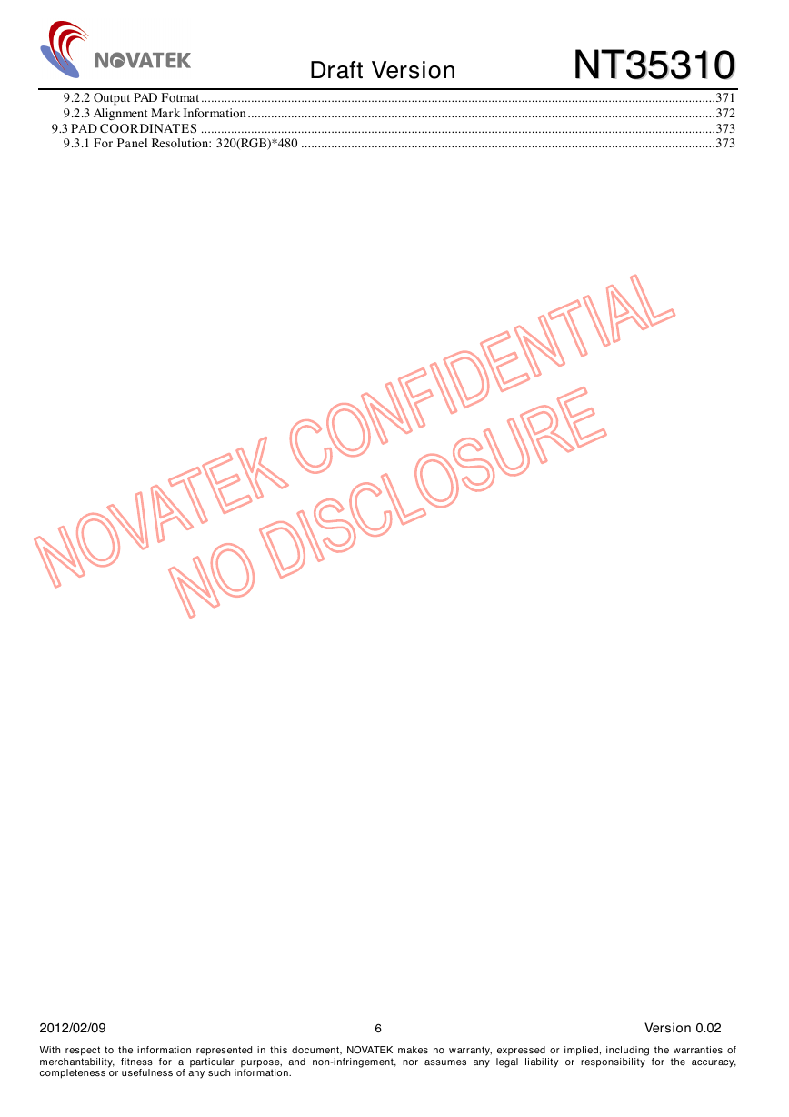
9.2.2 Output PAD Fotmat..........................................................................................................................................................371
9.2.3 Alignment Mark Information............................................................................................................................................372
9.3 PAD COORDINATES ..........................................................................................................................................................373
9.3.1 For Panel Resolution: 320(RGB)*480 ............................................................................................................................373
2012/02/09 6 Version 0.02
With respect to the information represented in this document, NOVATEK makes no warranty, expressed or implied, including the warranties of
merchantability, fitness for a particular purpose, and non-infringement, nor assumes any legal liability or responsibility for the accuracy,
completeness or usefulness of any such information.
�
Draft Version NNTT3355331100
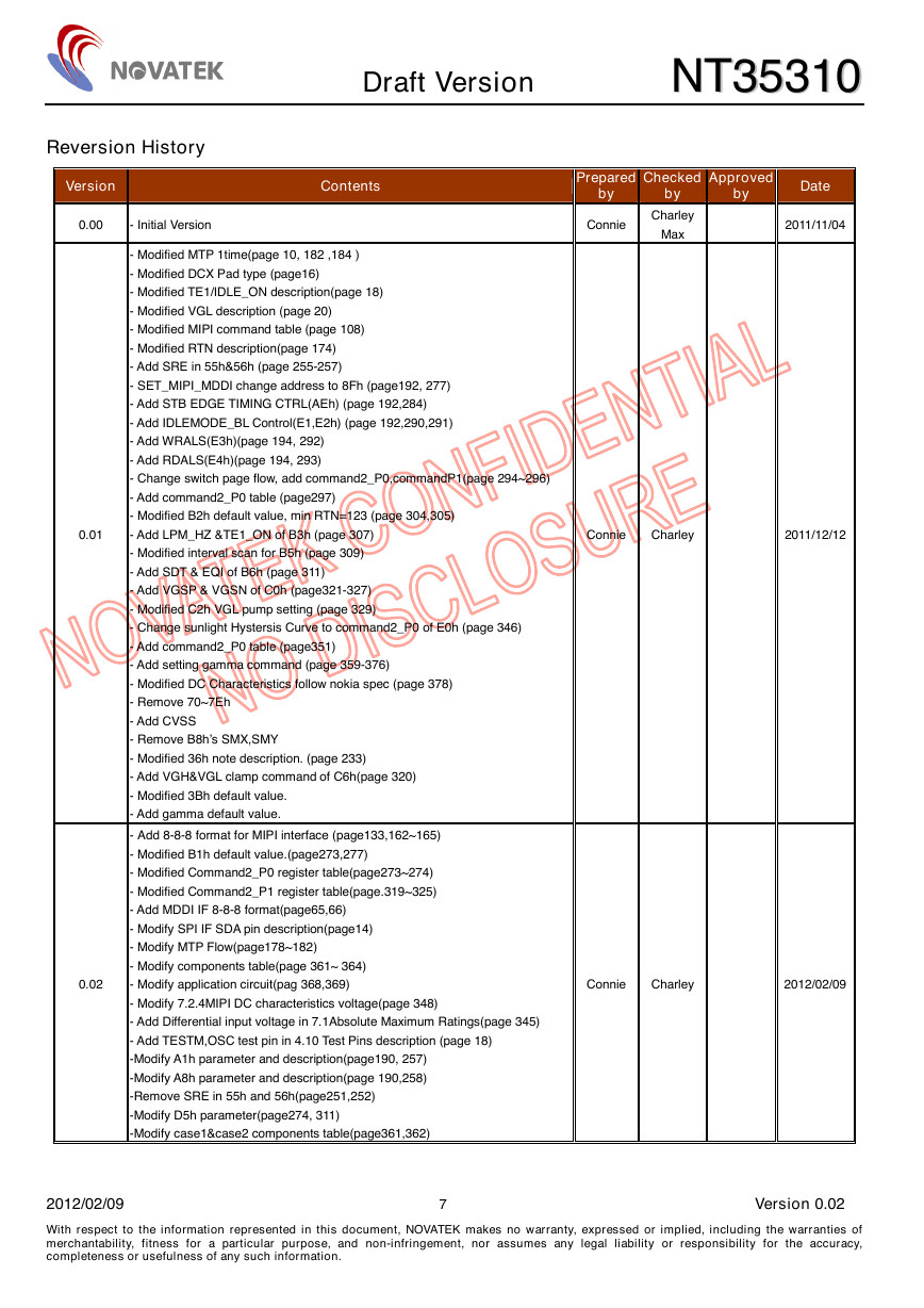
Reversion History
Version
Contents
0.00
- Initial Version
Prepared
by
Checked
by
Approved
by
Date
Connie
Charley
Max
2011/11/04
- Modified MTP 1time(page 10, 182 ,184 )
- Modified DCX Pad type (page16)
- Modified TE1/IDLE_ON description(page 18)
- Modified VGL description (page 20)
- Modified MIPI command table (page 108)
- Modified RTN description(page 174)
- Add SRE in 55h&56h (page 255-257)
- SET_MIPI_MDDI change address to 8Fh (page192, 277)
- Add STB EDGE TIMING CTRL(AEh) (page 192,284)
- Add IDLEMODE_BL Control(E1,E2h) (page 192,290,291)
- Add WRALS(E3h)(page 194, 292)
- Add RDALS(E4h)(page 194, 293)
- Change switch page flow, add command2_P0,commandP1(page 294~296)
- Add command2_P0 table (page297)
- Modified B2h default value, min RTN=123 (page 304,305)
- Add LPM_HZ &TE1_ON of B3h (page 307)
- Modified interval scan for B5h (page 309)
- Add SDT & EQI of B6h (page 311)
- Add VGSP & VGSN of C0h (page321-327)
- Modified C2h VGL pump setting (page 329)
- Change sunlight Hystersis Curve to command2_P0 of E0h (page 346)
- Add command2_P0 table (page351)
- Add setting gamma command (page 359-376)
- Modified DC Characteristics follow nokia spec (page 378)
- Remove 70~7Eh
- Add CVSS
- Remove B8h’s SMX,SMY
- Modified 36h note description. (page 233)
- Add VGH&VGL clamp command of C6h(page 320)
- Modified 3Bh default value.
- Add gamma default value.
- Add 8-8-8 format for MIPI interface (page133,162~165)
- Modified B1h default value.(page273,277)
- Modified Command2_P0 register table(page273~274)
- Modified Command2_P1 register table(page.319~325)
- Add MDDI IF 8-8-8 format(page65,66)
- Modify SPI IF SDA pin description(page14)
- Modify MTP Flow(page178~182)
- Modify components table(page 361~ 364)
- Modify application circuit(pag 368,369)
- Modify 7.2.4MIPI DC characteristics voltage(page 348)
- Add Differential input voltage in 7.1Absolute Maximum Ratings(page 345)
- Add TESTM,OSC test pin in 4.10 Test Pins description (page 18)
-Modify A1h parameter and description(page190, 257)
-Modify A8h parameter and description(page 190,258)
-Remove SRE in 55h and 56h(page251,252)
-Modify D5h parameter(page274, 311)
-Modify case1&case2 components table(page361,362)
0.01
0.02
Connie
Charley
2011/12/12
Connie
Charley
2012/02/09
2012/02/09 7 Version 0.02
With respect to the information represented in this document, NOVATEK makes no warranty, expressed or implied, including the warranties of
merchantability, fitness for a particular purpose, and non-infringement, nor assumes any legal liability or responsibility for the accuracy,
completeness or usefulness of any such information.
�
Draft Version NNTT3355331100
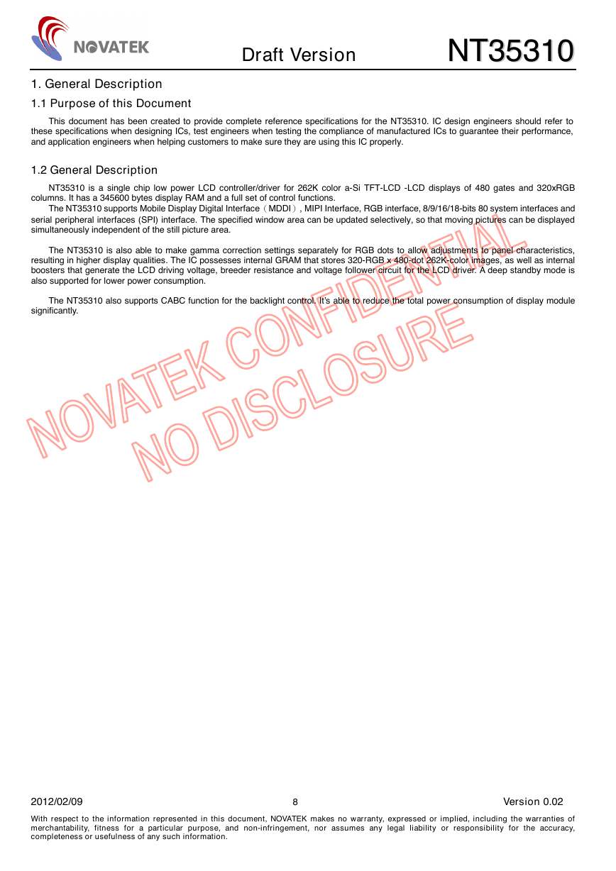
1. General Description
1.1 Purpose of this Document
This document has been created to provide complete reference specifications for the NT35310. IC design engineers should refer to
these specifications when designing ICs, test engineers when testing the compliance of manufactured ICs to guarantee their performance,
and application engineers when helping customers to make sure they are using this IC properly.
1.2 General Description
NT35310 is a single chip low power LCD controller/driver for 262K color a-Si TFT-LCD -LCD displays of 480 gates and 320xRGB
columns. It has a 345600 bytes display RAM and a full set of control functions.
The NT35310 supports Mobile Display Digital Interface(MDDI), MIPI Interface, RGB interface, 8/9/16/18-bits 80 system interfaces and
serial peripheral interfaces (SPI) interface. The specified window area can be updated selectively, so that moving pictures can be displayed
simultaneously independent of the still picture area.
The NT35310 is also able to make gamma correction settings separately for RGB dots to allow adjustments to panel characteristics,
resulting in higher display qualities. The IC possesses internal GRAM that stores 320-RGB x 480-dot 262K-color images, as well as internal
boosters that generate the LCD driving voltage, breeder resistance and voltage follower circuit for the LCD driver. A deep standby mode is
also supported for lower power consumption.
The NT35310 also supports CABC function for the backlight control. It’s able to reduce the total power consumption of display module
significantly.
2012/02/09 8 Version 0.02
With respect to the information represented in this document, NOVATEK makes no warranty, expressed or implied, including the warranties of
merchantability, fitness for a particular purpose, and non-infringement, nor assumes any legal liability or responsibility for the accuracy,
completeness or usefulness of any such information.
�
