Switching Mode Transformers
EEL12 Platforms - THT
LED Lighting T8/T10 Solution
AC/DC Switching Transformers
Reinforced Insulation
3000Vrms Hi-Pot
Topology: PFC Flyback
Electrical Specifications @ 25°C - Operating Temperature -40°C to +125°C
(2 - 1)
(2 - 1)
(2-1):(4-5)
(2-1):(8-9)
(2-1)
(4-5)
(8-9)
Pri-Sec
2162.7
(2 - 1)
(2 - 1)
(2-1):(4-5)
(2-1):(8-9)
(2-1)
(4-5)
(8-9)
Pri-Sec
2338.1
(2 - 1)
(2 - 1)
(2-1):(4-5)
(2-1):(9-8)
(2-1)
(4-5)
(9-8)
Pri-Sec
2473.6
(3 - 1)
(3 - 1)
(3-1):(5-4)
(3-1):(7-6)
(3-1):(9-8)
(3-1)
(5-4)
(7-6)
(9-8)
Pri-Sec
1709.4
545 µH +/- 15%
6.5 µH MAX
6.80
2.83
Ω Max
1.20
0.33
0.20
3000 Vrms
545 µH +/- 15%
14.0 µH MAX
9.250
2.846
Ω Max
1.30
0.23
0.22
3000 Vrms
715 µH +/- 15%
32.0 µH MAX
3.55
1.77
Ω Max
1.65
0.70
0.80
3000 Vrms
280 µH +/- 15%
6.0 µH MAX
6.500
1.625
6.500
Ω Max
0.95
0.42
0.55
0.16
3000 Vrms
85-264VAC
80KHz MIN
12V, 100mA
2
3
1
4
5
9
40V, 0.45A
8
DM PFC FLYBACK TRANSFORMER
85-264VAC
70KHz MIN
12V, 100mA
2
3
1
4
5
9
40V, 0.54A
8
DM PFC FLYBACK TRANSFORMER
20V, 0.1A
85-264VAC
65KHz
4
5
2
1
8
50V, 0.30A
9
DM PFC FLYBACK TRANSFORMER
90-265VAC
100KHz
14.7V, 0.05A
3
2
1
5
4
6
50V, 0.32A
7
8
12V, 0.05A
9
DM PFC FLYBACK TRANSFORMER
PG1054.400NL
Chipset:
TI UCC28810
Pri. Inductance
Lk. Inductance
Turn Ratio
DCR
Hi-Pot
K1 Factor
Pri. Inductance
Lk. Inductance
PG1054.404NL
Turn Ratio
Chipset:
Fairchild
FL7930C
PG1054.500NL
Chipset:
PI LNK406EG
PG1054.501NL
Chipset:
Intersil
ISL6745A
DCR
Hi-Pot
K1 Factor
Pri. Inductance
Lk. Inductance
Turn Ratio
DCR
Hi-Pot
K1 Factor
Pri. Inductance
Lk. Inductance
Turn Ratio
DCR
Hi-Pot
K1 Factor
USA 858 674 8100
Germany 49 7032 7806 0
Singapore 65 6287 8998
Shanghai 86 21 62787060
China 86 755 33966678
Taiwan 886 3 4356768
1
pulseelectronics.com
P701.C (08/11)
�
Switching Mode Transformers
EEL12 Platforms - THT
Mechanicals
PG1054.XXXNL
NOTES:
1. The temperature of the component (ambient plus
temperature rise) must be within the stated
operating temperature range.
2. For flyback technology applications, it is necessary
to ensure that the transformer will not saturate in
the application. The peak flux density (Bpk) should
remain below 2700 Gauss. To calculate the peak
flux density, use the following formula:
Bpk (Gauss) = K1_Factor * Ipk(A)
3. In high volt-µsec applications, it is important
to calculate the core loss of the transformer.
Approximate transformer core loss can be
calculated as:
CoreLoss (W) = 1.98E-07 X (Freq_kHz)ˆ1·38 X (DB_Gauss)ˆ2·86
where DB can be calculated as:
For Flyback Topology: DB = K1_Factor * 0.59Ipk(A)
4. The “NL” suffix indicates an RoHS-compliant part
number. Non-NL suffixed parts are not necessarily
RoHS compliant, but are electrically and mechanically
equivalent to NL versions. If a part number does not
have the “NL” suffix, but an RoHS-compliant version is
required, please contact Pulse for availabilty.
5. Full pins is available.
For More Information
Pulse Worldwide
Headquarters
12220 World Trade Drive
San Diego, CA
92128
U.S.A.
Pulse Europe
Einsteinstrasse 1
D-71083 Herren-
berg
Germany
Tel: 858 674 8100
Tel: 49 7032 7806
Pulse China Headquarters
B402, Shenzhen Academy of
Aerospace Technol-
ogy Bldg.
10th Kejinan Road
High-Tech Zone
Nanshan District
Shenzen, PR China
518057
Pulse North China
Room 2704/2705
Super Ocean Finance
Ctr.
2067 Yan An Road
West
Shanghai 200336
China
Pulse South Asia
135 Joo Seng Road
#03-02
PM Industrial Bldg.
Singapore 368363
Tel: 65 6287 8998
Fax: 65 6287 8998
Pulse North Asia
3F, No. 198
Zhongyuan Road
Zhongli City
Taoyuan County 320
Taiwan R. O. C.
Tel: 886 3 4356768
Fax: 886 3 4356823
(Pulse)
Performance warranty of products offered on this data sheet is limited to the parameters specified. Data is subject to change without notice. Other brand and product names mentioned herein may be
trademarks or registered trademarks of their respective owners. © Copyright, 2011. Pulse Electronics, Inc. All rights reserved.
2
pulseelectronics.com
P701.C (08/11)
�

.pdf-第1页.png")
.pdf-第2页.png")
 Meta大模型论文:The Llama 3 Herd of Models.pdf
 ACS0709(传感器资料).PDF
 495个C语言常见问题集.pdf
 CS型可燃性气体传感器(106型和1003型)(传感器资料).pdf
 一种基于PWM的电压输出DAC电路设计.pdf
 cd4011b(智能车电机驱动).pdf
 电路设计规范_中兴.pdf
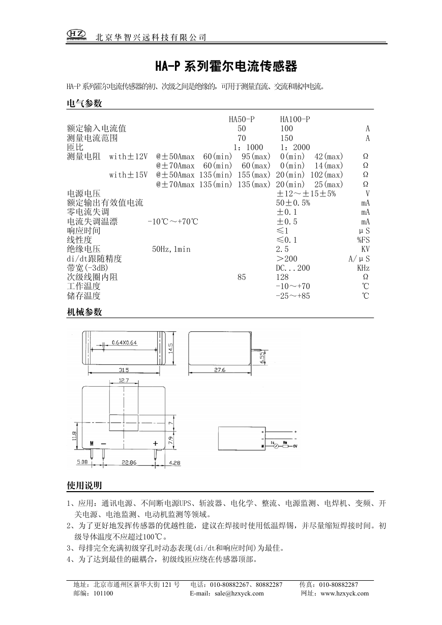 HA50-P(传感器资料).pdf
 ETD-core(TDK磁芯资料).pdf