R61505U
262,144-color, 240RGB x 320 dot graphics liquid crystal
controller driver for Amorphous-Silicon TFT Panel
REJxxxxxxx-xxxx
Rev.1.1
October 30, 2006
Description ......................................................................................................... 6
Features
......................................................................................................... 7
Difference between R61505 and R61505U.................................................................................................................10
Block Diagram .................................................................................................... 11
Block Function.................................................................................................... 12
1. System Interface ....................................................................................................................................................12
2. External Display Interface (RGB, VSYNC interfaces) .......................................................................................13
3. Address Counter (AC) ...........................................................................................................................................13
4. Graphics RAM (GRAM) .......................................................................................................................................14
5. Grayscale Voltage Generating Circuit .................................................................................................................14
6. Liquid crystal drive power supply circuit .............................................................................................................14
7. Timing Generator ..................................................................................................................................................14
8. Oscillator (OSC) ....................................................................................................................................................14
9. Liquid crystal driver Circuit..................................................................................................................................14
10. Internal logic power supply regulator ..................................................................................................................14
Pin Function ........................................................................................................ 15
PAD arrangement................................................................................................ 22
PAD coordinates ................................................................................................. 24
BUMP arrangement ............................................................................................ 39
Connection example............................................................................................ 40
GRAM address map............................................................................................ 41
Instruction ......................................................................................................... 43
Outline ..........................................................................................................................................................................43
Instruction Data Format .............................................................................................................................................43
Index (IR) .....................................................................................................................................................................44
Display control .............................................................................................................................................................44
Device code read (R00h)........................................................................................................................................44
Rev. 1.1 October 30, 2006, page 1 of 202
�
R61505U
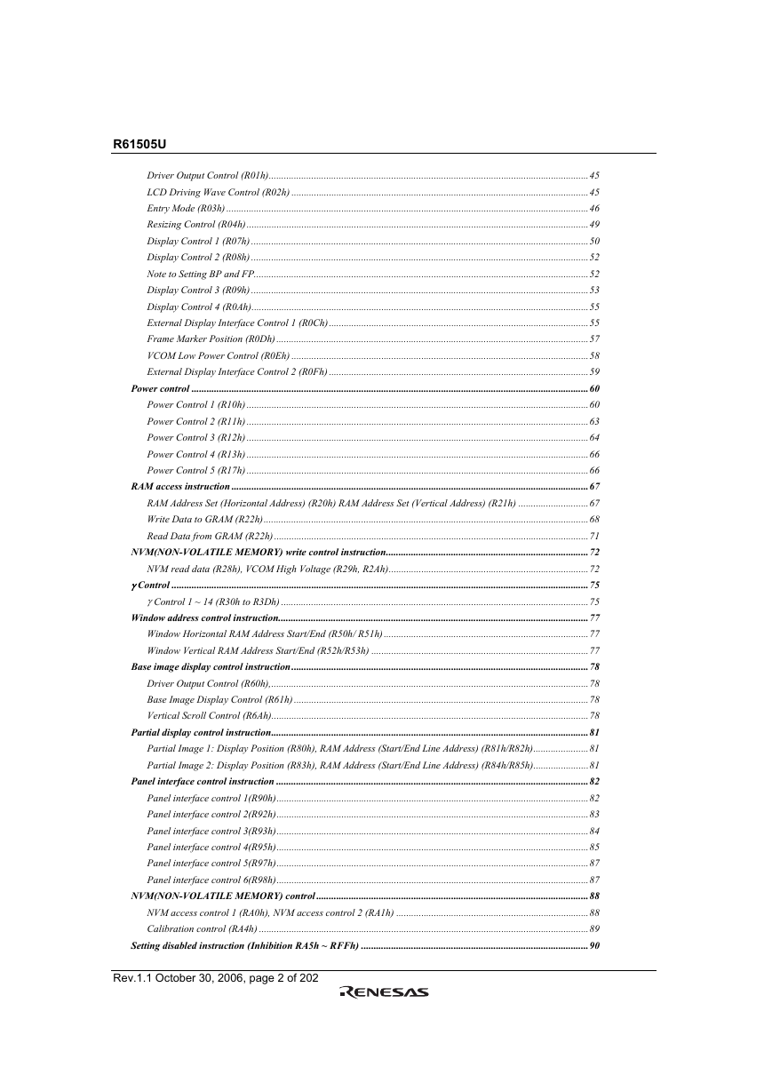
Driver Output Control (R01h)................................................................................................................................45
LCD Driving Wave Control (R02h) .......................................................................................................................45
Entry Mode (R03h) .................................................................................................................................................46
Resizing Control (R04h).........................................................................................................................................49
Display Control 1 (R07h) .......................................................................................................................................50
Display Control 2 (R08h) .......................................................................................................................................52
Note to Setting BP and FP......................................................................................................................................52
Display Control 3 (R09h) .......................................................................................................................................53
Display Control 4 (R0Ah).......................................................................................................................................55
External Display Interface Control 1 (R0Ch)........................................................................................................55
Frame Marker Position (R0Dh).............................................................................................................................57
VCOM Low Power Control (R0Eh) .......................................................................................................................58
External Display Interface Control 2 (R0Fh) ........................................................................................................59
Power control ...............................................................................................................................................................60
Power Control 1 (R10h) .........................................................................................................................................60
Power Control 2 (R11h) .........................................................................................................................................63
Power Control 3 (R12h) .........................................................................................................................................64
Power Control 4 (R13h) .........................................................................................................................................66
Power Control 5 (R17h) .........................................................................................................................................66
RAM access instruction ...............................................................................................................................................67
RAM Address Set (Horizontal Address) (R20h) RAM Address Set (Vertical Address) (R21h) ............................67
Write Data to GRAM (R22h)..................................................................................................................................68
Read Data from GRAM (R22h)..............................................................................................................................71
NVM(NON-VOLATILE MEMORY) write control instruction.................................................................................72
NVM read data (R28h), VCOM High Voltage (R29h, R2Ah)................................................................................72
γ Control .......................................................................................................................................................................75
γ Control 1 ~ 14 (R30h to R3Dh) ...........................................................................................................................75
Window address control instruction............................................................................................................................77
Window Horizontal RAM Address Start/End (R50h/ R51h)..................................................................................77
Window Vertical RAM Address Start/End (R52h/R53h) .......................................................................................77
Base image display control instruction.......................................................................................................................78
Driver Output Control (R60h),...............................................................................................................................78
Base Image Display Control (R61h) ......................................................................................................................78
Vertical Scroll Control (R6Ah)...............................................................................................................................78
Partial display control instruction...............................................................................................................................81
Partial Image 1: Display Position (R80h), RAM Address (Start/End Line Address) (R81h/R82h)......................81
Partial Image 2: Display Position (R83h), RAM Address (Start/End Line Address) (R84h/R85h)......................81
Panel interface control instruction .............................................................................................................................82
Panel interface control 1(R90h).............................................................................................................................82
Panel interface control 2(R92h).............................................................................................................................83
Panel interface control 3(R93h).............................................................................................................................84
Panel interface control 4(R95h).............................................................................................................................85
Panel interface control 5(R97h).............................................................................................................................87
Panel interface control 6(R98h).............................................................................................................................87
NVM(NON-VOLATILE MEMORY) control .............................................................................................................88
NVM access control 1 (RA0h), NVM access control 2 (RA1h) .............................................................................88
Calibration control (RA4h) ....................................................................................................................................89
Setting disabled instruction (Inhibition RA5h ~ RFFh) ...........................................................................................90
Rev.1.1 October 30, 2006, page 2 of 202
�
R61505U
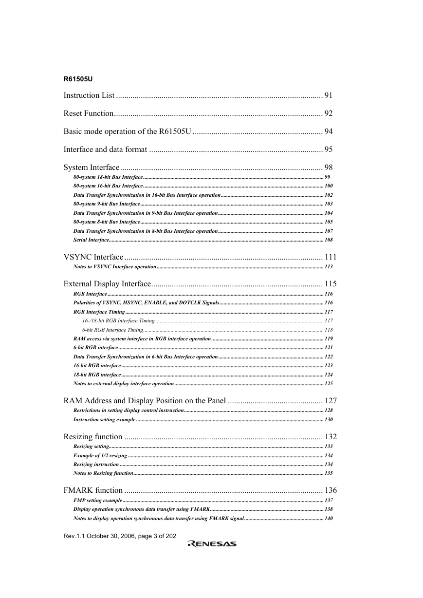
Instruction List .................................................................................................... 91
Reset Function..................................................................................................... 92
Basic mode operation of the R61505U ............................................................... 94
Interface and data format .................................................................................... 95
System Interface.................................................................................................. 98
80-system 18-bit Bus Interface....................................................................................................................................99
80-system 16-bit Bus Interface....................................................................................................................................100
Data Transfer Synchronization in 16-bit Bus Interface operation...........................................................................102
80-system 9-bit Bus Interface......................................................................................................................................103
Data Transfer Synchronization in 9-bit Bus Interface operation.............................................................................104
80-system 8-bit Bus Interface......................................................................................................................................105
Data Transfer Synchronization in 8-bit Bus Interface operation.............................................................................107
Serial Interface.............................................................................................................................................................108
VSYNC Interface................................................................................................ 111
Notes to VSYNC Interface operation..........................................................................................................................113
External Display Interface................................................................................... 115
RGB Interface ..............................................................................................................................................................116
Polarities of VSYNC, HSYNC, ENABLE, and DOTCLK Signals............................................................................116
RGB Interface Timing .................................................................................................................................................117
16-/18-bit RGB Interface Timing ...........................................................................................................................117
6-bit RGB Interface Timing....................................................................................................................................118
RAM access via system interface in RGB interface operation..................................................................................119
6-bit RGB interface......................................................................................................................................................121
Data Transfer Synchronization in 6-bit Bus Interface operation.............................................................................122
16-bit RGB interface....................................................................................................................................................123
18-bit RGB interface....................................................................................................................................................124
Notes to external display interface operation .............................................................................................................125
RAM Address and Display Position on the Panel .............................................. 127
Restrictions in setting display control instruction......................................................................................................128
Instruction setting example .........................................................................................................................................130
Resizing function ................................................................................................ 132
Resizing setting.............................................................................................................................................................133
Example of 1/2 resizing ...............................................................................................................................................134
Resizing instruction .....................................................................................................................................................134
Notes to Resizing function...........................................................................................................................................135
FMARK function ................................................................................................ 136
FMP setting example ...................................................................................................................................................137
Display operation synchronous data transfer using FMARK...................................................................................138
Notes to display operation synchronous data transfer using FMARK signal ..........................................................140
Rev.1.1 October 30, 2006, page 3 of 202
�
R61505U
High-speed RAM Write Function....................................................................... 141
Notes to high-speed RAM write function....................................................................................................................142
High-speed RAM data write in a window address area .............................................................................................143
Window Address Function ................................................................................. 144
Scan Mode Setting .............................................................................................. 145
8-color Display Mode ......................................................................................... 146
Line Inversion AC Drive .................................................................................... 147
Alternating Timing.......................................................................................................................................................148
Frame-Frequency Adjustment Function ............................................................. 149
Relationship between liquid crystal drive duty and frame frequency .......................................................................149
Partial Display Function ..................................................................................... 150
Liquid crystal panel interface timing .................................................................. 151
Internal clock operation...............................................................................................................................................151
RGB interface operation..............................................................................................................................................152
Oscillator
......................................................................................................... 153
γ Correction function .......................................................................................... 154
γ Correction registers ...................................................................................................................................................154
γ Correction register settings and γ curve relationship..............................................................................................156
Power-supply Generating Circuit ....................................................................... 157
Power supply circuit connection example 1 (VCI1 = VCIOUT) ...............................................................................157
Power supply circuit connection example 2 (VCI1 = VCI direct input) ...................................................................158
Specifications of Power-supply Circuit External Elements................................ 159
Voltage Setting Pattern Diagram ........................................................................ 160
Liquid crystal application voltage waveform and electrical potential.......................................................................161
VCOMH voltage adjustment sequence............................................................... 162
NVM control sequence ....................................................................................... 164
NVM Write In Sequence..............................................................................................................................................165
NVM Read Out Sequence............................................................................................................................................165
Power supply Instruction Setting........................................................................ 168
Notes to Power Supply ON sequence ................................................................. 169
Instruction setting................................................................................................ 170
Rev.1.1 October 30, 2006, page 4 of 202
�
R61505U
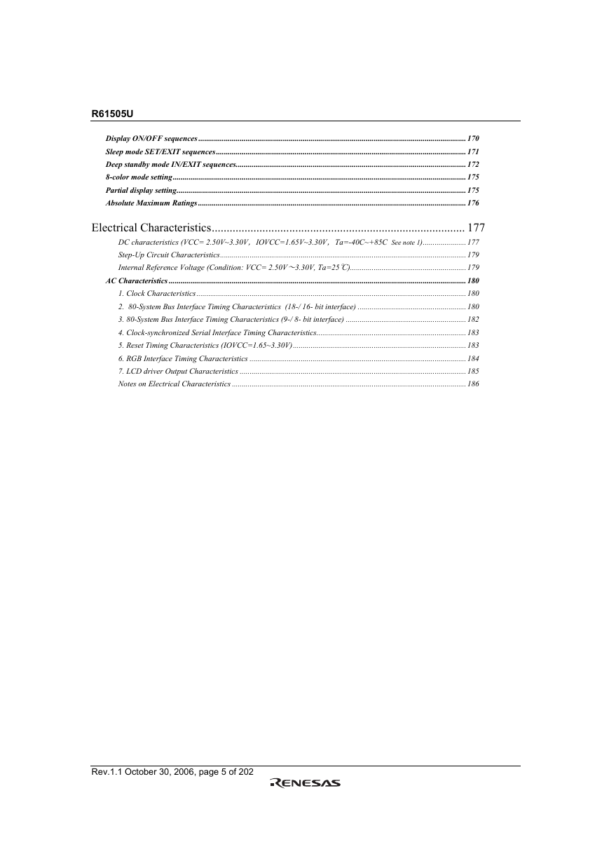
Display ON/OFF sequences ........................................................................................................................................170
Sleep mode SET/EXIT sequences...............................................................................................................................171
Deep standby mode IN/EXIT sequences.....................................................................................................................172
8-color mode setting.....................................................................................................................................................175
Partial display setting...................................................................................................................................................175
Absolute Maximum Ratings ........................................................................................................................................176
Electrical Characteristics..................................................................................... 177
DC characteristics (VCC= 2.50V~3.30V,IOVCC=1.65V~3.30V,Ta=-40C~+85C See note 1)......................177
Step-Up Circuit Characteristics.............................................................................................................................179
Internal Reference Voltage (Condition: VCC= 2.50V~3.30V, Ta=25℃)...........................................................179
AC Characteristics .......................................................................................................................................................180
1. Clock Characteristics.........................................................................................................................................180
2. 80-System Bus Interface Timing Characteristics (18-/ 16- bit interface) .......................................................180
3. 80-System Bus Interface Timing Characteristics (9-/ 8- bit interface) .............................................................182
4. Clock-synchronized Serial Interface Timing Characteristics............................................................................183
5. Reset Timing Characteristics (IOVCC=1.65~3.30V)........................................................................................183
6. RGB Interface Timing Characteristics ..............................................................................................................184
7. LCD driver Output Characteristics ...................................................................................................................185
Notes on Electrical Characteristics .......................................................................................................................186
Rev.1.1 October 30, 2006, page 5 of 202
�
R61505U
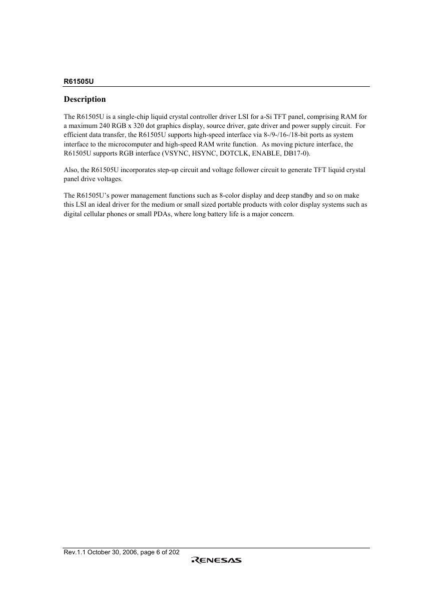
Description
The R61505U is a single-chip liquid crystal controller driver LSI for a-Si TFT panel, comprising RAM for
a maximum 240 RGB x 320 dot graphics display, source driver, gate driver and power supply circuit. For
efficient data transfer, the R61505U supports high-speed interface via 8-/9-/16-/18-bit ports as system
interface to the microcomputer and high-speed RAM write function. As moving picture interface, the
R61505U supports RGB interface (VSYNC, HSYNC, DOTCLK, ENABLE, DB17-0).
Also, the R61505U incorporates step-up circuit and voltage follower circuit to generate TFT liquid crystal
panel drive voltages.
The R61505U’s power management functions such as 8-color display and deep standby and so on make
this LSI an ideal driver for the medium or small sized portable products with color display systems such as
digital cellular phones or small PDAs, where long battery life is a major concern.
Rev.1.1 October 30, 2006, page 6 of 202
�
R61505U
Features
• A single-chip controller driver incorporating a gate circuit and a power supply circuit for a maximum
•
240RGB x 320dots graphics display on amorphous TFT panel in 262k colors
System interface
– High-speed interfaces via 8-, 9-, 16-, 18-bit parallel ports
– Clock synchronous serial interface
• Moving picture display interface
6-, 16-, 18-bit RGB interface (VSYNC, HSYNC, DOTCLK, ENABLE, DB17-0)
–
– VSYNC interface (System interface + VSYNC)
–
FMARK interface (System interface + FMARK)
• High-speed RAM write function
• Window address function to specify a rectangular area in the internal RAM to write data
• Write data within a rectangular area in the internal RAM via moving picture interface
•
•
•
• Abundant color display and drawing functions
Reduce data transfer by specifying the area in the RAM to rewrite data
Enable displaying the data in the still picture RAM area with a moving picture simultaneously
Resizing function (x 1/2, x 1/4)
Programmable γ-correction function for 262k-color display
Partial display function
–
–
Low -power consumption architecture (allowing direct input of interface I/O power supply)
– Deep standby function
–
8-color display function
–
Input power supply voltages: VCC = 2.5V ~ 3.3 V (logic regulator power supply)
IOVCC = 1.65V ~ 3.3 V (interface I/O power supply)
•
•
•
•
•
•
•
•
VCI = 2.5V ~ 3.3 V (liquid crystal analog circuit power supply)
Incorporates a liquid crystal drive power supply circuit
–
Source driver liquid crystal drive/VCOM power supply: DDVDH-GND = 4.5V ~ 6.0 V
VCL-GND = -1.9V ~ -3.0V
VCI-VCL ≤ 6.0V
– Gate drive power supply: VGH-GND = 10.0V ~ 20.0 V
VGL-GND = -4.5V ~ -13.5V
VGH-VGL ≤ 28.0V
– VCOM drive (VCOM power supply): VCOMH = 3.0V ~ (DDVDH-0.5)V
VCOML = (VCL+0.5)V ~ 0V
VCOMH-VCOML amplitude = 6.0V (max.)
Liquid crystal power supply startup sequencer
TFT storage capacitance: Cst only (common VCOM formula)
172,800-byte internal RAM
Internal 720-channel source driver and 320-channel gate driver
Single-chip solution for COG module with the arrangement of gate circuits on both sides of the glass
substrate
Internal NVM: User identification code, 4 bits, VCOM level adjustment, 5 bits x 2 sets
Rev.1.1 October 30, 2006, page 7 of 202
�
R61505U
Internal reference voltage: to generate VREG1OUT (VCIR)
•
• Product Numbers
The R61505U has two variations of frequencies enabling users to choose whichever suitable for display
system.
Product Number
R61505U0
R61505U1
Oscillation Frequency
376KHz
600KHz
Rev.1.1 October 30, 2006, page 8 of 202
�

