Micriµm
© Copyright 2006, Micriµm
All Rights reserved
µC/OS-II
ARM Cortex-M3 Processors
and
Application Note
AN-1018
HTUwww.Micrium.comUTH
�
µC/OS-II for the ARM Cortex-M3 Processors
Table of Contents
1.00
2.00
3.00
3.01
3.02
3.02.01
3.02.02
3.02.03
3.02.04
3.02.05
3.02.06
3.03
3.03.01
3.03.02
3.03.03
3.03.04
3.03.05
3.03.06
3.04
3.04.01
3.04.02
3.04.03
3.04.04
3.04.05
3.04.06
3.05
4.00
4.01
4.02
4.03
5.00
5.01
5.02
6.00
6.01
Introduction................................................................................................... 4
The ARM Cortex-M3 programmer’s model................................................... 6
µC/OS-II Port for the ARM Cortex-M3 processors...................................... 9
Directories and Files................................................................................... 10
OS_CPU.H ................................................................................................. 11
OS_CPU.H, macros for ‘externals’ ............................................................. 11
OS_CPU.H, Data Types............................................................................. 11
OS_CPU.H, Critical Sections...................................................................... 12
OS_CPU.H, Stack growth .......................................................................... 12
OS_CPU.H, Task Level Context Switch ..................................................... 13
OS_CPU.H, Function Prototypes ............................................................... 13
OS_CPU_C.C............................................................................................. 14
OS_CPU_C.C, OSInitHookBegin()............................................................. 14
OS_CPU_C.C, OSTaskCreateHook() ........................................................ 15
OS_CPU_C.C, OSTaskStkInit() ................................................................. 16
OS_CPU_C.C, OSTaskSwHook().............................................................. 18
OS_CPU_C.C, OSTimeTickHook() ............................................................ 18
OS_CPU_C.C, OS_CPU_SysTickInit() ...................................................... 19
OS_CPU_A.ASM........................................................................................ 20
OS_CPU_A.ASM, OS_CPU_SR_Save() ................................................... 20
OS_CPU_A.ASM, OS_CPU_SR_Restore() ............................................... 20
OS_CPU_A.ASM, OSStartHighRdy()......................................................... 21
OS_CPU_A.ASM, OSCtxSw().................................................................... 22
OS_CPU_A.ASM, OSIntCtxSw()................................................................ 23
OS_CPU_A.ASM, OS_CPU_PendSVHandler() ......................................... 23
OS_DBG.C................................................................................................. 27
Exception Vector Table .............................................................................. 28
Exception / Interrupt Handling Sequence ................................................... 29
Interrupt Controllers.................................................................................... 29
Interrupt Service Routines .......................................................................... 29
Application Code ........................................................................................ 30
APP.C, APP.H and APP_CFG.H................................................................ 31
INCLUDES.H.............................................................................................. 34
BSP (Board Support Package)................................................................... 35
BSP (Board Support Package) – LED Management .................................. 35
2
�
µC/OS-II for ARM Cortex-M3 Processors
................................................................................................................... 37
Conclusion.................................................................................................. 36
7.00
Licensing
References ................................................................................................................... 37
Contacts
Notes
................................................................................................................... 37
................................................................................................................... 38
3
�
µC/OS-II for the ARM Cortex-M3 Processors
Introduction
1.00
ARM has been working on a new architecture called the Cortex for a number of years. During
development, µC/OS-II was used to validate some of the design aspects and was used as a source of
ideas to create new capabilities to support RTOSs. In other words, µC/OS-II was the first RTOS ported
to the Cortex.
This application note describes the ‘official’ Micrium port for µC/OS-II on the Cortex-M3 processor.
Figure 1-1 shows a block diagram showing the relationship between your application, µC/OS-II, the port
code and the BSP (Board Support Package). Relevant sections of this application note are referenced
on the figure.
4
�
µC/OS-II for ARM Cortex-M3 Processors
Your Application
APP.C
APP_VECT.C
APP_CFG.H
INCLUDES.H
OS_CFG.H
Section 5
µC/OS-II
Book
µC/OS-II
OS_CORE.C
OS_FLAG.C
OS_MBOX.C
OS_MEM.C
OS_MUTEX.C
OS_Q.C
OS_SEM.C
OS_TASK.C
OS_TIME.C
OS_TMR.C
uCOS_II.H
Section 3
µC/OS-II
Cortex M3 Port
OS_CPU_C.C
OS_CPU_A.ASM
OS_CPU.H
OS DBG.C
BSP
BSP.C
BSP.H
Section 6
Section 2
ARM Cortex-M3 / Target Board
Figure 1-1, Relationship between modules.
5
�
µC/OS-II for the ARM Cortex-M3 Processors
The ARM Cortex-M3 programmer’s model
2.00
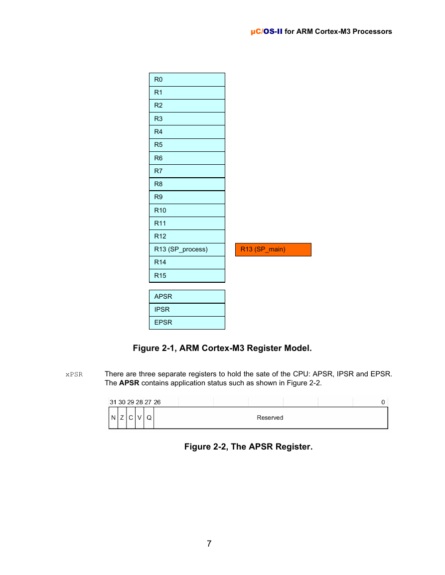
The visible registers in an ARM Cortex-M3 processor are shown in Figure 2-1. The ARM Cortex-M3 has
a total of 20 registers. Each register is 32 bits wide.
R0 through R12 are general purpose registers that can be used to hold data as well as
pointers.
Is generally designated as the stack pointer (also called the SP) but could be the recipient
of arithmetic operations. There are actually two stack pointers (SP_process and
SP_main) but only one is visible at any given time. SP_process is used for task level
code and SP_main is used for exception processing.
Is called the Link Register (LR) and is used to store the contents of the PC when a
Branch and Link (BL) instruction is executed. The LR allows you to return to the caller.
Is dedicated to be used as the Program Counter (PC) and points to the current instruction
being executed. As instructions are executed, the PC is incremented by either 2 or 4
depending on the instruction.
R0-R12
R13
R14
R15
6
�
xPSR
µC/OS-II for ARM Cortex-M3 Processors
R0
R1
R2
R3
R4
R5
R6
R7
R8
R9
R10
R11
R12
R13 (SP_process)
R13 (SP_main)
R14
R15
APSR
IPSR
EPSR
Figure 2-1, ARM Cortex-M3 Register Model.
There are three separate registers to hold the sate of the CPU: APSR, IPSR and EPSR.
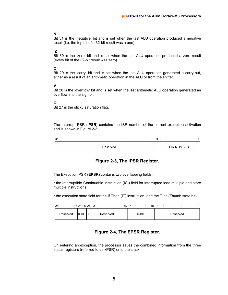
The APSR contains application status such as shown in Figure 2-2.
Figure 2-2, The APSR Register.
7
�
µC/OS-II for the ARM Cortex-M3 Processors
N
Bit 31 is the ‘negative’ bit and is set when the last ALU operation produced a negative
result (i.e. the top bit of a 32-bit result was a one).
Z
Bit 30 is the ‘zero’ bit and is set when the last ALU operation produced a zero result
(every bit of the 32-bit result was zero).
C
Bit 29 is the ‘carry’ bit and is set when the last ALU operation generated a carry-out,
either as a result of an arithmetic operation in the ALU or from the shifter.
V
Bit 28 is the ‘overflow’ bit and is set when the last arithmetic ALU operation generated an
overflow into the sign bit.
Q
Bit 27 is the sticky saturation flag.
The Interrupt PSR (IPSR) contains the ISR number of the current exception activation
and is shown in Figure 2-3.
Figure 2-3, The IPSR Register.
The Execution PSR (EPSR) contains two overlapping fields:
• the Interruptible-Continuable Instruction (ICI) field for interrupted load multiple and store
multiple instructions
• the execution state field for the If-Then (IT) instruction, and the T-bit (Thumb state bit).
Figure 2-4, The EPSR Register.
On entering an exception, the processor saves the combined information from the three
status registers (referred to as xPSR) onto the stack.
8
�
