logo资料库

CiA301在电机控制上的实现指导.pdf

第1页 / 共118页
第2页 / 共118页
第3页 / 共118页
第4页 / 共118页
第5页 / 共118页
第6页 / 共118页
第7页 / 共118页
第8页 / 共118页
资料共118页,剩余部分请下载后查看
Chapter 1: Introduction
1.1 Relevant Documentation
1.1.1 Elmo Documentation
1.1.2 CAN Documentation
1.2 Terms and Abbreviations
1.3 SimplIQ Communication
Chapter 2: CANopen Basics
2.1 Physical Layer
2.2 Standard vs. Extended Addressing
2.3 Client - Server Relations
2.4 Inhibit Times
2.5 RTR – Remote Transmission Request
2.6 Object Dictionary
2.7 Communication Objects
2.8 Object Dictionary - Data Types
2.9 Representation of Numbers
Chapter 3: The Object Dictionary
Chapter 4: Service Data Objects (SDOs)
4.1 Initiate SDO Download Protocol
4.2 Download SDO Protocol
4.3 Initiate SDO Upload Protocol
4.4 Upload SDO Segment Protocol
4.5 Abort SDO Transfer Protocol
4.6 Uploading Data Using an SDO
4.7 Downloading Data Using an SDO
4.8 Error Correction
Chapter 5: Process Data Objects (PDOs)
5.1 Receive PDOs
5.2 Transmit PDOs
5.3 PDO Mapping
5.3.1 The Mapping Trigger – Transmission Type
5.3.2 The Synchronous Trigger
5.3.3 The Asynchronous Trigger
5.3.4 RPDO Error Handling
5.3.5 Mapping Parameter Objects
5.3.6 Default Values
Chapter 6: Emergency (EMCY)
6.1 Emergency Configuration
6.2 Emergency Codes Related to Failure
6.3 Emergency Codes for Motor Faults
6.4 Emergency Codes Related to PVT/PT Motion
Chapter 7: Network Management (NMT)
Chapter 8: SYNC and Time Stamp
Chapter 9: Binary Interpreter Commands
9.1 Binary Interpreter Commands and Results
9.1.1 Set and Query Commands
9.1.1.1 RPDO2 Structure
9.1.1.1 TPDO2 Structure
9.1.2 Execute Command
9.2 ASCII Interpreter Commands not Supportedby Binary Interpreter
Chapter 10: The OS Interpreter
Chapter 11: The EDS
Chapter 12: Communication Profile
Object 0x1000: Device type
Object 0x1001: Error register
Object 0x1002: Manufacturer status register
Object 0x1003: Pre-defined error field
Object 0x1005: COB-ID SYNC message
Object 0x1008: Manufacturer device name
Object 0x1009: Manufacturer hardware version
Object 0x100A: Manufacturer software version
Object 0x100B: Node ID
Object 0x1010: Save parameters
Object 0x1011: Restore parameters
Object 0x1012: COB-ID time stamp
Object 0x1013: High-resolution time stamp
Object 0x1014: COB-ID emergency object
Object 0x1016: Consumer heartbeat time
Object 0x1017: Producer heartbeat time
Object 0x1018: Identity object
Object 0x1023: OS command and prompt
Object 0x1024: OS command mode
Object 0x1029: Error behavior
Object 0x1200: SDO server parameter
Objects 0x1400 - 0x1403: Receive PDO communication parameter
Objects 0x1800 - 0x1803: Transmit PDO communication parameter
Objects 0x1A00 - 0x1A03: Transmit PDO mapping
Chapter 13: Manufacturer-specific Objects
Object 0x2001: PVT data
Object 0x2002: PT data
Object 0x2004: ECAM data
Object 0x2012: Binary interpreter input
Object 0x2013: Binary interpreter output
Object 0x2030: Recorder data
Object 0x2040: Coordinate system group ID
Object 0x2041: Amplifier-free running timer
Object 0x2082: CAN controller status
Object 0x2090: Firmware download
Object 0x20A0: Auxiliary position actual value
Object 0x20A1: Main position error
Object 0x2200: Digital input
Object 0x2201: Digital input low byte
Object 0x2205: Analog Input Object
Object 0x2F00: User Integer
Object 0x2F01: User Float Array
Object 0x2F02: ET Array
Object 0x2F11: PVT head pointer
Object 0x2F12: PVT tail pointer
Object 0x2F15: Profile position remaining points
Object 0x2F20: PDO events
Object 0x2F21: Emergency events
Object 0x2F22: Bus off time out
Object 0x2F23: Digital input TPDO event parameters
Object 0x2F30: Last time stamp correction
Object 0x2F31: Last SYNC time
Object 0x2F40: Configuration object
Object 0x2F41: DS402 Configuration object
Object 0x2F60 – Zero torque threshold
Object 0x2F70 – CAN Encoder Range
Chapter 14: Error Control Protocol
Chapter 15: Downloading Firmware
Chapter 16: Initial CAN Communication Setup
16.1 Setup Using RS-232
16.2 Bootup Protocol
Appendix A: Little and Big Endians
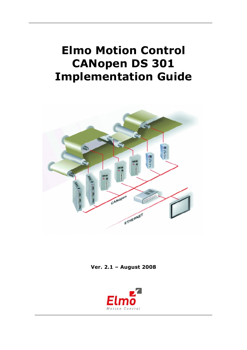
Elmo Motion Control CANopen DS 301 Implementation Guide Ver. 2.1 – August 2008
CANopen DS 301 Implementation Guide MAN-CAN301IG (Ver. 2.1) Important Notice This guide is delivered subject to the following conditions and restrictions: This guide contains proprietary information belonging to Elmo Motion Control Ltd. Such information is supplied solely for the purpose of assisting users of SimplIQ servo drives in implementing CANopen networking. The text and graphics included in this manual are for the purpose of illustration and reference only. The specifications on which they are based are subject to change without notice. Information in this document is subject to change without notice. Corporate and individual names and data used in examples herein are fictitious unless otherwise noted. Doc. No. MAN-CAN301IG Copyright © 2008 Elmo Motion Control Ltd. All rights reserved. Revision History: Version Rel. Date Status Ver 2.1 August 2008 Ver 2.0 Oct 2007 MAN-CAN301IG Changes/Remarks Updated note for 0x1017. Updated note for 0x2082. 0x2205: Analog input can be converted to physical units. Updated the example. 0x2082 can be mapped Updated 0x2F60. Added note to 0xF70. All dummy entries can be mapped Added object 0x2F60, 0x2F70 Added State Machine graphic to Ch. 7 Added note to 0x2082 Added note to 0x1017 Added object 0x2205 Elmo Motion Control Ltd. 64 Gissin St., P.O. Box 463 Petach Tikva 49103 Israel Tel: +972 (3) 929-2300 Fax: +972 (3) 929-2322 info-il@elmomc.com Elmo Motion Control Inc. 1 Park Drive, Suite 12 Westford, MA 01886 USA Tel: +1 (978) 399-0034 Fax: +1 (978) 399-0035 info-us@elmomc.com Elmo Motion Control GmbH Steinkirchring 1 D-78056, Villingen-Schwenningen Germany Tel: +49 (0) 7720-85 77 60 Fax: +49 (0) 7720-85 77 70 info-de@elmomc.com www.elmomc.com
CANopen DS 301 Implementation Guide MAN-CAN301IG (Ver. 2.1) i Contents Chapter 1: Introduction .......................................................................................................... 1-1 1.1 Relevant Documentation ............................................................................. 1-1 1.1.1 Elmo Documentation........................................................................................ 1-1 1.1.2 CAN Documentation........................................................................................ 1-2 1.2 Terms and Abbreviations............................................................................. 1-2 1.3 SimplIQ Communication ............................................................................... 1-3 Chapter 2: CANopen Basics................................................................................................... 2-1 2.1 Physical Layer ........................................................................................... 2-1 2.2 Standard vs. Extended Addressing................................................................ 2-1 2.3 Client - Server Relations .............................................................................. 2-1 2.4 Inhibit Times ............................................................................................. 2-2 2.5 RTR – Remote Transmission Request............................................................. 2-2 2.6 Object Dictionary ....................................................................................... 2-2 2.7 Communication Objects .............................................................................. 2-3 2.8 Object Dictionary - Data Types ..................................................................... 2-4 2.9 Representation of Numbers.......................................................................... 2-7 Chapter 3: The Object Dictionary......................................................................................... 3-1 Chapter 4: Service Data Objects (SDOs).............................................................................. 4-1 4.1 Initiate SDO Download Protocol................................................................... 4-2 4.2 Download SDO Protocol ............................................................................. 4-3 4.3 Initiate SDO Upload Protocol ....................................................................... 4-4 4.4 Upload SDO Segment Protocol ..................................................................... 4-5 4.5 Abort SDO Transfer Protocol........................................................................ 4-6 4.6 Uploading Data Using an SDO ..................................................................... 4-7 4.7 Downloading Data Using an SDO................................................................. 4-8 4.8 Error Correction......................................................................................... 4-8 Chapter 5: Process Data Objects (PDOs) ............................................................................. 5-1 5.1 Receive PDOs ............................................................................................ 5-1 5.2 Transmit PDOs .......................................................................................... 5-3 5.3 PDO Mapping ........................................................................................... 5-3 5.3.1 The Mapping Trigger – Transmission Type................................................... 5-4 5.3.2 The Synchronous Trigger................................................................................. 5-4 5.3.3 The Asynchronous Trigger .............................................................................. 5-5 5.3.4 RPDO Error Handling ...................................................................................... 5-5 5.3.5 Mapping Parameter Objects............................................................................. 5-6 5.3.6 Default Values ................................................................................................... 5-7 Chapter 6: Emergency (EMCY).............................................................................................. 6-1 6.1 Emergency Configuration............................................................................ 6-1 6.2 Emergency Codes Related to Failure ............................................................. 6-1 6.3 Emergency Codes for Motor Faults ............................................................... 6-1 6.4 Emergency Codes Related to PVT/PT Motion................................................. 6-1 Chapter 7: Network Management (NMT)............................................................................ 7-1 Chapter 8: SYNC and Time Stamp ....................................................................................... 8-1
CANopen DS 301 Implementation Guide MAN-CAN301IG (Ver. 2.1) Contents ii Chapter 9: Binary Interpreter Commands ........................................................................... 9-1 9.1 Binary Interpreter Commands and Results ..................................................... 9-2 9.1.1 Set and Query Commands ............................................................................... 9-2 9.1.1.1 RPDO2 Structure ............................................................................... 9-2 9.1.1.1 TPDO2 Structure................................................................................ 9-4 9.1.2 Execute Command............................................................................................ 9-5 9.2 ASCII Interpreter Commands not Supported by Binary Interpreter .................... 9-6 Chapter 10: The OS Interpreter ........................................................................................... 10-1 Chapter 11: The EDS............................................................................................................. 11-1 Chapter 12: Communication Profile................................................................................... 12-1 Object 0x1000: Device type...................................................................................................... 12-1 Object 0x1001: Error register................................................................................................... 12-2 Object 0x1002: Manufacturer status register........................................................................... 12-3 Object 0x1003: Pre-defined error field...................................................................................... 12-3 Object 0x1005: COB-ID SYNC message.................................................................................. 12-4 Object 0x1008: Manufacturer device name .............................................................................. 12-5 Object 0x1009: Manufacturer hardware version...................................................................... 12-6 Object 0x100A: Manufacturer software version ...................................................................... 12-6 Object 0x100B: Node ID .......................................................................................................... 12-7 Object 0x1010: Save parameters .............................................................................................. 12-7 Object 0x1011: Restore parameters .......................................................................................... 12-8 Object 0x1012: COB-ID time stamp ........................................................................................ 12-9 Object 0x1013: High-resolution time stamp........................................................................... 12-10 Object 0x1014: COB-ID emergency object............................................................................. 12-11 Object 0x1016: Consumer heartbeat time............................................................................... 12-12 Object 0x1017: Producer heartbeat time................................................................................. 12-13 Object 0x1018: Identity object ............................................................................................... 12-14 Object 0x1023: OS command and prompt.............................................................................. 12-15 Object 0x1024: OS command mode........................................................................................ 12-17 Object 0x1029: Error behavior ............................................................................................... 12-17 Object 0x1200: SDO server parameter................................................................................... 12-18 Objects 0x1400 - 0x1403: Receive PDO communication parameter ...................................... 12-20 Objects 0x1800 - 0x1803: Transmit PDO communication parameter ................................... 12-23 Objects 0x1A00 - 0x1A03: Transmit PDO mapping............................................................. 12-25 Chapter 13: Manufacturer-specific Objects....................................................................... 13-1 Object 0x2001: PVT data......................................................................................................... 13-1 Object 0x2002: PT data............................................................................................................ 13-2 Object 0x2004: ECAM data ..................................................................................................... 13-3 Object 0x2012: Binary interpreter input.................................................................................. 13-4 Object 0x2013: Binary interpreter output................................................................................ 13-4 Object 0x2030: Recorder data .................................................................................................. 13-5 Object 0x2040: Coordinate system group ID ......................................................................... 13-10 Object 0x2041: Amplifier-free running timer ........................................................................ 13-11 Object 0x2082: CAN controller status................................................................................... 13-11 Object 0x208A: Begin time .................................................................................................... 13-13 Object 0x2090: Firmware download....................................................................................... 13-13
CANopen DS 301 Implementation Guide MAN-CAN301IG (Ver. 2.1) Contents iii Object 0x20A0: Auxiliary position actual value .................................................................... 13-14 Object 0x20A1: Main position error ...................................................................................... 13-15 Object 0x2200: Digital input ................................................................................................. 13-15 Object 0x2201: Digital input low byte ................................................................................... 13-16 Object 0x2205: Analog Input Object ................................................................................... 13-17 Then the reading obtained is:.............................................................................................. 13-18 Object 0x2F00: User Integer .................................................................................................. 13-18 Object 0x2F01: User Float Array........................................................................................... 13-19 Object 0x2F02: ET Array...................................................................................................... 13-20 Object 0x2F11: PVT head pointer .......................................................................................... 13-20 Object 0x2F12: PVT tail pointer............................................................................................ 13-21 Object 0x2F15: Profile position remaining points .................................................................. 13-21 Object 0x2F21: Emergency events ......................................................................................... 13-24 Object 0x2F22: Bus off time out............................................................................................. 13-29 Object 0x2F23: Digital input TPDO event parameters.......................................................... 13-29 Object 0x2F30: Last time stamp correction ............................................................................ 13-31 Object 0x2F31: Last SYNC time............................................................................................ 13-31 Object 0x2F40: Configuration object...................................................................................... 13-32 Object 0x2F41: DS402 Configuration object.......................................................................... 13-33 Object 0x2F60 – Zero torque threshold .............................................................................. 13-34 Object 0x2F70 – CAN Encoder Range ................................................................................ 13-35 Chapter 14: Error Control Protocol ..................................................................................... 14-1 Chapter 15: Downloading Firmware .................................................................................. 15-1 Chapter 16: Initial CAN Communication Setup............................................................... 16-1 16.1 Setup Using RS-232................................................................................... 16-1 16.2 Bootup Protocol ....................................................................................... 16-2 Appendix A: Little and Big Endians ....................................................................................A-1
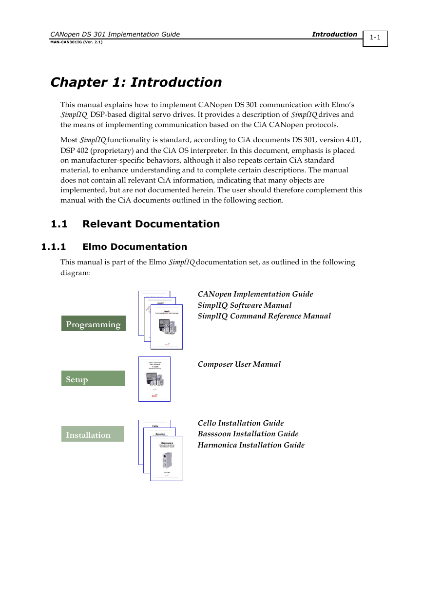
CANopen DS 301 Implementation Guide MAN-CAN301IG (Ver. 2.1) Introduction 1-1 Chapter 1: Introduction This manual explains how to implement CANopen DS 301 communication with Elmo’s SimplIQ DSP-based digital servo drives. It provides a description of SimplIQ drives and the means of implementing communication based on the CiA CANopen protocols. Most SimplIQ functionality is standard, according to CiA documents DS 301, version 4.01, DSP 402 (proprietary) and the CiA OS interpreter. In this document, emphasis is placed on manufacturer-specific behaviors, although it also repeats certain CiA standard material, to enhance understanding and to complete certain descriptions. The manual does not contain all relevant CiA information, indicating that many objects are implemented, but are not documented herein. The user should therefore complement this manual with the CiA documents outlined in the following section. 1.1 Relevant Documentation 1.1.1 Elmo Documentation This manual is part of the Elmo SimplIQ documentation set, as outlined in the following diagram: Programming Setup Installation CANopen Implementation Guide SimplIQ Software Manual SimplIQ Command Reference Manual Composer User Manual Cello Installation Guide Basssoon Installation Guide Harmonica Installation Guide
CANopen DS 301 Implementation Guide MAN-CAN301IG (Ver. 2.1) Introduction 1-2 In addition to this document, the SimplIQ documentation set includes: The SimplIQ Installation Guide, which provides full instructions for installing the SimplIQ digital servo drives The Composer User Manual, which includes explanations of all the software tools that are a part of Elmo’s Composer software environment The SimplIQ Command Reference Manual, which describes, in detail, each software command used to manipulate the SimplIQ motion controller. This is the main source of detailed explanations of all SimplIQ commands mentioned in this manual. The SimplIQ Software Manual, which describes the comprehensive software used with SimplIQ digital servo drives 1.1.2 CAN Documentation Document Name CAN Implementation Guidelines CiA DS 301 V 4.01: CANopen Communication Profile for Industrial Systems - based on CAL CiA DS 302 V 3.0: CANopen Framework for Programmable Devices CiA DS 305 V 1.0: CANopen Layer Setting Services and Protocol (LSS) CiA DSP 402 V 2.0: CANopen Device Profile CiA DS 202-2 V 1.1: CAN Application Layer (CAL ) - CMS Protocol Specification Author Gruhler G. and Drier B. Source STA Reutlingen CiA CiA CiA CiA CiA 1.2 Terms and Abbreviations The following terms and abbreviations are used in this manual: Term / Abbreviation Definition CAL CAN client or master A host — typically a PC — or other control equipment that CAN application layer. CAN server or CAN slave CMS COB supervises the nodes of a network. A node in the CAN network that can give service under control of the CAN master. CAN message specification. Communication object; a CAN message.
CANopen DS 301 Implementation Guide MAN-CAN301IG (Ver. 2.1) Introduction 1-3 Term / Abbreviation Definition COB-ID EDS ID LSB LSS MSB Object OD PLC Receive Transmit A binary bit-field that includes the ID of the server with which the master talks, and the type of COB. Electronic data sheet; a standard form of all CAN objects supported by a device. The EDS is used by external CAN configurators. Identifier; the name by which a CAN device is addressed. Least Significant Bit (or Byte) Layer setting service: methods for configuring the ID and baud rate of a slave, using the standard DSP 305. Most Significant Bit (or Byte) A CAN message with a meaningful functionality and/or data. Objects are referenced according to addresses in the object dictionary. DO: Data object. Object dictionary, which is the full set of objects supported by the node. It is the interface between the application and communication (see “Object” below.) Programmable controller. A PLC can serve as a CAN master for SimplIQ digital servo drives. In this manual, “received” data is sent from the control equipment to the servo drive. In this manual, “transmitted” data is sent from the servo drive to the other equipment. Table 1-1: Terms and Abbreviations 1.3 SimplIQ Communication SimplIQ digital servo drives support two types of serial communication: RS-232 CANopen SimplIQ digital servo drives can simultaneously communicate using both CAN and RS- 232 communication lines, which are always open for communication. The communication parameters are set using the PP command.
分享到:
收藏