InvenSense Inc.
1197 Borregas Ave., Sunnyvale, CA 94089 U.S.A.
Tel: +1 (408) 988-7339 Fax: +1 (408) 988-8104
Website: www.invensense.com
Document Number:
Revision: 1.0
Release Date: 12/19/2012
Embedded Motion Driver 5.1.1 Tutorial
A printed copy of this document is
NOT UNDER REVISION CONTROL
unless it is dated and stamped in red ink as,
“REVISION CONTROLLED COPY.”
This information furnished by InvenSense is believed to be accurate and reliable. However, no responsibility is assumed by InvenSense for its use, or for
any infringements of patents or other rights of third parties that may result from its use. Specifications are subject to change without notice. InvenSense
reserves the right to make changes to this product, including its circuits and software, in order to improve its design and/or performance, without prior
notice. InvenSense makes no warranties, neither expressed nor implied, regarding the information and specifications contained in this document.
InvenSense assumes no responsibility for any claims or damages arising from information contained in this document, or from the use of products and
services detailed therein. This includes, but is not limited to, claims or damages based on the infringement of patents, copyrights, mask work and/or other
intellectual property rights.
Certain intellectual property owned by InvenSense and described in this document is patent protected. No license is granted by implication or otherwise
under any patent or patent rights of InvenSense. This publication supersedes and replaces all information previously supplied. Trademarks that are
registered trademarks are the property of their respective companies. InvenSense sensors should not be used or sold in the development, storage,
production or utilization of any conventional or mass-destructive weapons or for any other weapons or life threatening applications, as well as in any other
life critical applications such as medical equipment, transportation, aerospace and nuclear instruments, undersea equipment, power plant equipment,
disaster prevention and crime prevention equipment.
Copyright ©2011 InvenSense Corporation.
�
Embedded Motion Driver 5.1.1 Tutorial
Document Number:
Revision: 1.0
Release Date: 12/19/2012
TABLE OF CONTENTS
1. REVISION HISTORY ................................................................................................................................... 3
2. PURPOSE .................................................................................................................................................... 3
3. REQUIREMENTS ........................................................................................................................................ 3
4.
INTRODUCTION TO MOTION DRIVER...................................................................................................... 4
5. OPENING UP THE MOTION DRIVER PROJECT IN CODE COMPOSER STUDIO ................................. 5
6. EXPLAINING MOTION DRIVER AND THE FUNCTIONAL SPECIFICATION IN MORE DETAIL ............ 5
6.1
6.2
6.3
6.4
6.5
6.6
6.7
6.8
DMP ................................................................................................................................................... 5
I2C DRIVER TO INTERFACE WITH INVENSENSE IC .................................................................................. 6
GYROSCOPE AND ACCELEROMETER SELF-TEST FUNCTION CALLS ........................................................... 7
ACCELEROMETER CALIBRATION ............................................................................................................ 7
GYROSCOPE CALIBRATION ................................................................................................................... 8
LOW POWER ACCELEROMETER MOTION INTERRUPT ............................................................................... 8
ABILITY TO CHANGE SENSOR ODRS OF THE GYROSCOPE AND ACCELEROMETER ..................................... 8
ABILITY TO SELECT WHICH DATA TO POPULATE IN THE FIFO USING A FUNCTION CALL .............................. 8
7. TESTING THE MOTION DRIVER USING THE MOTIONFIT SDK AND PYTHON SCRIPT ...................... 8
8. GET COMPASS DATA VIA MOTION DRIVER ........................................................................................ 10
9. COMPASS INTEGRATION AND CALIBRATION .................................................................................... 10
10. SPI DRIVER IMPLEMENTATION ............................................................................................................. 10
11. APPENDIX ................................................................................................................................................. 11
11.1
APPENDIX A ................................................................................................................................... 11
11.2
APPENDIX B ................................................................................................................................... 12
12. REFERENCES ........................................................................................................................................... 12
CONFIDENTIAL & PROPRIETARY
2 of 12
�
1. Revision History
Embedded Motion Driver 5.1.1 Tutorial
Document Number:
Revision: 1.0
Release Date: 12/19/2012
Revision Date
Revision
Description
12/19/2012
1.0
Document created
2. Purpose
Motion Driver is a sensor driver layer that easily configures and leverages the on board Digital Motion
Processor (DMP) capabilities of InvenSense’s Motion Tracking devices. Motion Driver is a subset of the
Embedded MotionApps software that enables easier porting to multiple MCU architectures. This document
illustrates the practical usage of the Motion Driver library. The included tutorial is written for compatibility with
the MSP430 embedded microcontroller from TI, and as such, some knowledge of the MSP430 architecture is
recommended. The MSP430 is used as an example platform only. Motion Driver can be ported easily to
any MCU.
3. Requirements
3.1 Code Composer Studio (to compile the MSP430 example only)
3.2 Motion Driver source files
3.3 MotionFit™ development board or similar hardware (for example only)
CONFIDENTIAL & PROPRIETARY
3 of 12
�
Embedded Motion Driver 5.1.1 Tutorial
Document Number:
Revision: 1.0
Release Date: 12/19/2012
4.
Introduction to Motion Driver
Motion Driver consists of a set of API’s written in ANSI compatible C to use and configure the different
functions of InvenSense Motion Tracking devices, including DMP operation. This tutorial provides a sample
project which sends out fused quaternion data from the accelerometer and gyroscope (6-axis Quaternion)
onto the serial port of the PC which is processed by a client written in python to display and rotate a 3
dimensional cube on the screen. The 6 axis and 9 axis InvenSense devices are supported in this driver.
The following is addressed in this Motion Driver tutorial:
- How to load, configure, and leverage DMP functions.
-
I2C driver example for the MSP430.
- Gyroscope and accelerometer self-test function calls based on the hardware self-test document.
(Please refer to the product Register Map document for full self-test descriptions).
- Accelerometer calibration and updating parameters within the hardware registers.
- Gyroscope calibration
- Configuring the low power accelerometer motion interrupt
- Ability to change the sensor Output Data Rate (ODR) of the gyroscope and accelerometer.
- Ability to select which data is populated in the FIFO.
CONFIDENTIAL & PROPRIETARY
4 of 12
�
Embedded Motion Driver 5.1.1 Tutorial
Document Number:
Revision: 1.0
Release Date: 12/19/2012
5. Opening up the Motion Driver Project in Code Composer Studio
1. Select import under the file menu.
2. Choose existing CCS eclipse project.
3. Click the browse button to select the Motion Driver folder.
4. Open the Motion Driver project by clicking finish.
Figure Shows steps 1 to 3 to open the motion driver project
Figure showing the step 4 and the final IDE with Motion Driver
5. Open the file motion_driver_test.c under the simple_apps folder. This file will be referred to as
the “main” file throughout this tutorial. The main file includes examples on how to configure the
Motion Driver and has in-source documentation to help users read through each line of code.
6. Explaining Motion Driver and the Functional Specification in More Detail
6.1 DMP
1. DMP and DMP features: The DMP is a unique hardware feature of InvenSense MPU devices
which is capable of computing quaternion data from sensor readings, performing device
calibration, and also includes application specific features such as pedometer step-counting. The
DMP image (firmware) is held in volatile memory on the MPU and needs to be updated to the
CONFIDENTIAL & PROPRIETARY
5 of 12
�
Embedded Motion Driver 5.1.1 Tutorial
Document Number:
Revision: 1.0
Release Date: 12/19/2012
DMP every time the chip powers up to leverage this functionality. The features which the Motion
Driver DMP image supports include:
a) DMP_FEATURE_LP_QUAT: This is a low power (gyro angle) three axis quaternion
which is calculated from the gyroscope data at 200HZ within the DMP.
b) DMP_FEATURE_6X_LP_QUAT: This is a low power six axis sensor fusion output
calculated from the gyroscope and accelerometer data at 200 Hz within the DMP.
c) DMP_FEATURE_TAP: This is a “tap” gesture feature where one can detect a tap event
and sense basic features such as single tap/double tap, or the direction of the tap.
d) DMP_FEATURE_ANDROID_ORIENT: This feature is the implementation of the display
orientation as compatible with Google Motion_driver devices. This feature includes a
state machine which calculates display orientation.
e) DMP_PEDOMETER: This is a step-counting feature that is always ON and running on
the DMP while the MPU is powered. The Motion Driver library can reset pedometer step
count value, query for the walk time, and return step count. There is a latency of 7 steps
before updating the step count number and walk time to improve accuracy and minimize
false-detection. This feature is always enabled as long as the DMP is enabled.
f) DMP_FEATURE_GYRO_CAL: This feature when enabled will calibrate the gyroscope
bias whenever the device is in the state of no-motion for more than 8 seconds.
g) DMP_FEATURE_SEND_RAW_ACCEL: Adds raw accelerometer data to the FIFO and
the accelerometer data is in chip coordinates
h) DMP_FEATURE_SEND_RAW_GYRO: Add raw gyro data to the FIFO. The gyroscope
coordinate is in the chip coordinates.
i) DMP_FEATURE_SEND_CAL_GYRO: Add calibrated gyro data to the FIFO. Cannot be
used in combination with DMP_FEATURE_SEND_RAW_GYRO. The output is in the
device frame or the body frame instead of chip frame.
2. Steps to load and enable DMP features: The sequence of updating the image and initializing the
DMP features is highlighted in the sample application provided within the Motion Driver library
project. These steps include:
the DMP
the MPU memory: Helper
a) Push
image
into
function
dmp_load_motion_driver_firmware is provided for this task.
b) Push the Gyroscope and Accelerometer Orientation Matrix to the DMP: An orientation
matrix can be sent to the DMP to transform the output orientation reference to the board
or device coordinate system. dmp_set_orientation () function updates the orientation matrix.
c) DMP Callbacks: Some DMP features register a call back to alert the main program.
These call backs get triggered when the features on the DMP, like orientation ready or
tap are detected. There are helper functions provided as an example in the Motion
Driver like dmp_register_android_orient_cb(android_orient_cb); for the orientation change feature.
Note that registering a call back does not enable a feature by default.
d) Enable DMP features: Helper function dmp_enable_feature () is provided.
e) Data Rate: The FIFO rate defines the output data rate of the DMP and can be updated
with the helper function mpu_set_fifo_rate (input).
6.2
I2C driver to interface with InvenSense IC
1. An I2C driver is implemented here for the MSP430F5528 platform and is given in source so that
it can be easily ported to any MCU platform. msp430_i2c_write and msp430_i2c_read functions provide
the primary functionality for reading and writing data while msp430_i2c_enable and msp430_i2c_disable
are the functions provided to enable and disable the I2C communication for the MSP430F5528.
These functions require the slave address, register address, length and data to be read and
written. Please check the file mps430_i2c.c for more details on the implementation.
CONFIDENTIAL & PROPRIETARY
6 of 12
�
Embedded Motion Driver 5.1.1 Tutorial
Document Number:
Revision: 1.0
Release Date: 12/19/2012
6.3 Gyroscope and accelerometer self-test function calls
The MPU’s gyroscope and accelerometer self-test feature permits users to test the mechanical
and electrical portions of the gyroscope and accelerometer. When the self-test is activated, the
on-board electronics will actuate the appropriate sensor. This actuation will move the gyroscope’s
proof masses over a distance equivalent to a pre-defined Coriolis force, simulating an external
force on the accelerometer. This results in a change in the sensor output, which is reflected in the
output signal. The output signal is used to observe the self-test response in combination with the
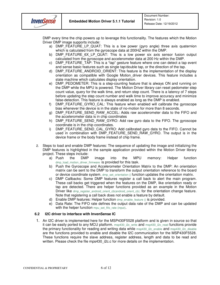
self-test registers. The self-test response (STR) is defined as follows:
݈݈݈݈݂݂݂݂ܵܵܵܵ݁݁݁݁ܶܶܶܶ݁݁݁݁ݏݏݏݏݐݐݐݐ ܴܴܴܴ݁݁݁݁ݏݏݏݏ݊݊݊݊ݏݏݏݏ݁݁݁݁ = Sensor ܱܱܱܱݑݑݑݑݐݐݐݐݑݑݑݑݐݐݐݐ ݓݓݓݓ݅݅݅݅ݐݐݐݐℎℎℎℎ ݈݈݈݈݂݂݂݂ܵܵܵܵ݁݁݁݁ܶܶܶܶ݁݁݁݁ݏݏݏݏݐݐݐݐ ܧܧܧܧܾܾܾܾ݈݈݈݈݊݊݊݊ܽܽܽܽ݁݁݁݁݀݀݀݀ − Sensor ܱܱܱܱݑݑݑݑݐݐݐݐݑݑݑݑݐݐݐݐ ݓݓݓݓ݅݅݅݅ݐݐݐݐℎℎℎℎ ݈݈݈݈݂݂݂݂ܵܵܵܵ݁݁݁݁ܶܶܶܶ݁݁݁݁ݏݏݏݏݐݐݐݐ ܦܦܦܦ݅݅݅݅ݏݏݏݏܾܾܾܾ݈݈݈݈ܽܽܽܽ݁݁݁݁݀݀݀݀
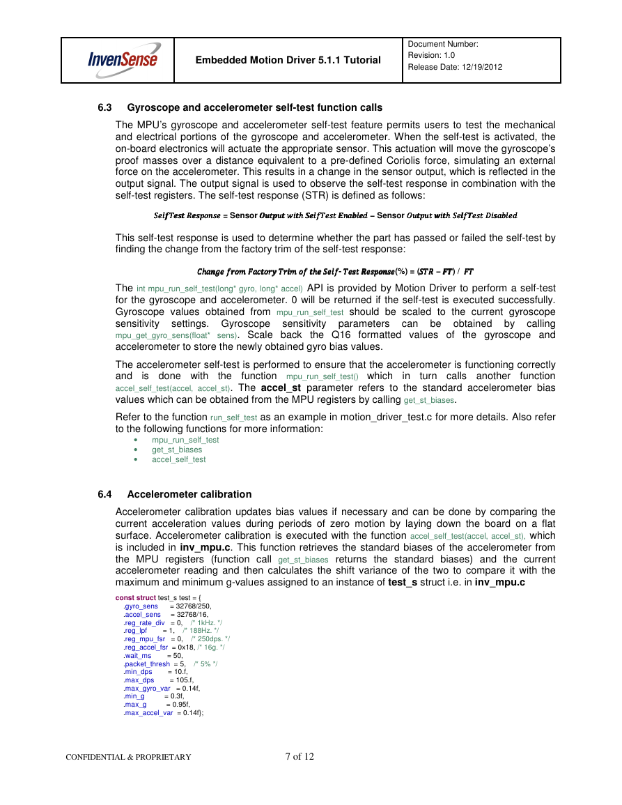
This self-test response is used to determine whether the part has passed or failed the self-test by
finding the change from the factory trim of the self-test response:
ܥܥܥܥℎℎℎℎܽܽܽܽ݊݊݊݊݃݃݃݃݁݁݁݁ ݂݂݂݂ݎݎݎݎ݉݉݉݉ ܨܨܨܨܽܽܽܽܿܿܿܿݐݐݐݐݎݎݎݎݕݕݕݕ ܶܶܶܶݎݎݎݎ݅݅݅݅݉݉݉݉ ݂݂݂݂ ݐݐݐݐℎℎℎℎ݁݁݁݁ ݈݈݈݈݂݂݂݂ܵܵܵܵ݁݁݁݁- ܶܶܶܶ݁݁݁݁ݏݏݏݏݐݐݐݐ ܴܴܴܴ݁݁݁݁ݏݏݏݏ݊݊݊݊ݏݏݏݏ݁݁݁݁(%) = (ܴܴܴܴܵܵܵܵܶܶܶܶ − ܨܨܨܨܶܶܶܶ) / ܨܨܨܨܶܶܶܶ
The int mpu_run_self_test(long* gyro, long* accel) API is provided by Motion Driver to perform a self-test
for the gyroscope and accelerometer. 0 will be returned if the self-test is executed successfully.
Gyroscope values obtained from mpu_run_self_test should be scaled to the current gyroscope
sensitivity settings. Gyroscope sensitivity parameters can be obtained by calling
mpu_get_gyro_sens(float* sens). Scale back the Q16 formatted values of the gyroscope and
accelerometer to store the newly obtained gyro bias values.
is done with
the
in
The accelerometer self-test is performed to ensure that the accelerometer is functioning correctly
and
function
accel_self_test(accel, accel_st). The accel_st parameter refers to the standard accelerometer bias
values which can be obtained from the MPU registers by calling get_st_biases.
function mpu_run_self_test() which
turn calls another
Refer to the function run_self_test as an example in motion_driver_test.c for more details. Also refer
to the following functions for more information:
• mpu_run_self_test
•
•
get_st_biases
accel_self_test
6.4 Accelerometer calibration
Accelerometer calibration updates bias values if necessary and can be done by comparing the
current acceleration values during periods of zero motion by laying down the board on a flat
surface. Accelerometer calibration is executed with the function accel_self_test(accel, accel_st), which
is included in inv_mpu.c. This function retrieves the standard biases of the accelerometer from
the MPU registers (function call get_st_biases returns the standard biases) and the current
accelerometer reading and then calculates the shift variance of the two to compare it with the
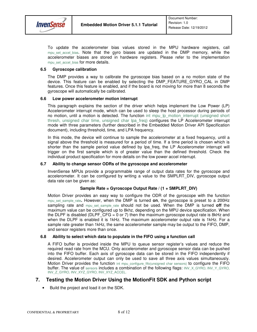
maximum and minimum g-values assigned to an instance of test_s struct i.e. in inv_mpu.c
const struct test_s test = {
.gyro_sens = 32768/250,
.accel_sens = 32768/16,
.reg_rate_div = 0, /* 1kHz. */
.reg_lpf = 1, /* 188Hz. */
.reg_mpu_fsr = 0, /* 250dps. */
.reg_accel_fsr = 0x18, /* 16g. */
.wait_ms = 50,
.packet_thresh = 5, /* 5% */
.min_dps = 10.f,
.max_dps = 105.f,
.max_gyro_var = 0.14f,
.min_g = 0.3f,
.max_g = 0.95f,
.max_accel_var = 0.14f};
CONFIDENTIAL & PROPRIETARY
7 of 12
�
Embedded Motion Driver 5.1.1 Tutorial
Document Number:
Revision: 1.0
Release Date: 12/19/2012
To update the accelerometer bias values stored in the MPU hardware registers, call
mpu_set_accel_bias. Note that the gyro biases are updated in the DMP memory, while the
accelerometer biases are stored in hardware registers. Please refer to the implementation
mpu_set_accel_bias for more details.
6.5 Gyroscope calibration
The DMP provides a way to calibrate the gyroscope bias based on a no motion state of the
device. This feature can be enabled by selecting the DMP_FEATURE_GYRO_CAL in DMP
features. Once this feature is enabled, and if the board is not moving for more than 8 seconds the
gyroscope will automatically be calibrated.
6.6 Low power accelerometer motion interrupt
This paragraph explains the section of the driver which helps implement the Low Power (LP)
Accelerometer interrupt mode, which can be used to sleep the host processor during periods of
no motion, until a motion is detected. The function int mpu_lp_motion_interrupt (unsigned short
thresh, unsigned char time, unsigned char lpa_freq) configures the LP Accelerometer interrupt
mode with three parameters (further described in the Embedded Motion Driver API Specification
document), including threshold, time, and LPA frequency.
In this mode, the device will continue to sample the accelerometer at a fixed frequency, until a
signal above the threshold is measured for a period of time. If a time period is chosen which is
shorter than the sample period value defined by lpa_freq, the LP Accelerometer interrupt will
trigger on the first sample which is of greater value than the defined threshold. Check the
individual product specification for more details on the low power accel interrupt.
6.7 Ability to change sensor ODRs of the gyroscope and accelerometer
InvenSense MPUs provide a programmable range of output data rates for the gyroscope and
accelerometer. It can be configured by writing a value to the SMPLRT_DIV, gyroscope output
data rate can be given as:
Sample Rate = Gyroscope Output Rate / (1 + SMPLRT_DIV)
Motion Driver provides an easy way to configure the ODR of the gyroscope with the function
mpu_set_sample_rate. However, when the DMP is turned on, the gyroscope is preset to a 200Hz
sampling rate and mpu_set_sample_rate should not be used. When the DMP is turned off the
maximum value can be configured up to 8khz, depending on the MPU device specification. When
the DLPF is disabled (DLPF_CFG = 0 or 7) then the maximum gyroscope output rate is 8kHz and
when the DLPF is enabled it is 1kHz. The maximum accelerometer output rate is 1kHz. For a
sample rate greater than 1kHz, the same accelerometer sample may be output to the FIFO, DMP,
and sensor registers more than once.
6.8 Ability to select which data to populate in the FIFO using a function call
A FIFO buffer is provided inside the MPU to queue sensor register’s values and reduce the
required read rate from the MCU. Only accelerometer and gyroscope sensor data can be pushed
into the FIFO buffer. Each axis of gyroscope data can be stored in the FIFO independently if
desired. Accelerometer output can only be used to save all three axis values simultaneously.
Motion Driver provides the function int mpu_configure_fifo(unsigned char sensors) to configure the FIFO
buffer. The value of sensors includes a combination of the following flags: INV_X_GYRO, INV_Y_GYRO,
INV_Z_GYRO, INV_XYZ_GYRO, INV_XYZ_ACCEL.
7.
Testing the Motion Driver Using the MotionFit SDK and Python script
• Build the project and load it on the SDK.
CONFIDENTIAL & PROPRIETARY
8 of 12
�
