BOSCH
CAN Specification
Version 2.0
1991, Robert Bosch GmbH, Postfach 30 02 40, D-70442 Stuttgart
�
BOSCH
CAN Specification 2.0
Sep. 1991
page 1
Recital
introduction of serial communication
The acceptance and
to more and more
applications has led to requirements that the assignment of message identifiers to
communication functions be standardized for certain applications. These applications
can be realized with CAN more comfortably, if the address range that originally has
been defined by 11 identifier bits is enlarged
Therefore a second message format (’extended format’) is introduced that provides a
larger address range defined by 29 bits. This will relieve the system designer from
compromises with respect to defining well-structured naming schemes. Users of CAN
who do not need the identifier range offered by the extended format, can rely on the
conventional 11 bit identifier range (’standard format’) further on. In this case they can
make use of the CAN implementations that are already available on the market, or of
new controllers that implement both formats.
In order to distinguish standard and extended format the first reserved bit of the CAN
message format, as it is defined in CAN Specification 1.2, is used. This is done in such
a way that the message format in CAN Specification 1.2 is equivalent to the standard
format and therefore is still valid. Furthermore, the extended format has been defined
so that messages in standard format and extended format can coexist within the same
network.
This CAN Specification consists of two parts, with
• Part A describing the CAN message format as it is defined in CAN Specification 1.2;
• Part B describing both standard and extended message formats.
In order to be compatible with this CAN Specification 2.0 it is required that a CAN
implementation be compatible with either Part A or Part B.
Note
CAN implementations that are designed according to part A of this or according to
previous CAN Specifications, and CAN implementations that are designed according to
part B of this specification can communicate with each other as long as it is not made
use of the extended format.
ROBERT BOSCH GmbH, Postfach 30 02 40, D-70442 Stuttgart
�
PART A
�
BOSCH
Contents
Sep. 1991
Part A - page 3
1
2
3
3.1
3.1.1
3.1.2
3.1.3
3.1.4
3.1.5
3.2
4
5
6
6.1
6.2
7
8
9
INTRODUCTION................................................................................4
BASIC CONCEPTS............................................................................5
MESSAGE TRANSFER .....................................................................10
Frame Types ......................................................................................10
DATA FRAME ....................................................................................10
REMOTE FRAME ..............................................................................15
ERROR FRAME.................................................................................16
OVERLOAD FRAME..........................................................................17
INTERFRAME SPACING...................................................................18
Definition of TRANSMITTER/RECEIVER ..........................................20
MESSAGE VALIDATION ...................................................................21
CODING.............................................................................................22
ERROR HANDLING...........................................................................23
Error Detection ...................................................................................23
Error Signalling...................................................................................23
FAULT CONFINEMENT.....................................................................24
BIT TIMING REQUIREMENTS ..........................................................27
INCREASING CAN OSCILLATOR TOLERANCE..............................31
9.1
Protocol Modifications ........................................................................31
ROBERT BOSCH GmbH, Postfach 30 02 40, D-70442 Stuttgart
�
BOSCH
Introduction
Sep. 1991
Part A - page 4
1 INTRODUCTION
The Controller Area Network (CAN) is a serial communications protocol which
efficiently supports distributed realtime control with a very high level of security.
Its domain of application ranges from high speed networks to low cost multiplex wiring.
In automotive electronics, engine control units, sensors, anti-skid-systems, etc. are
connected using CAN with bitrates up to 1 Mbit/s. At the same time it is cost effective to
build into vehicle body electronics, e.g. lamp clusters, electric windows etc. to replace
the wiring harness otherwise required.
The intention of this specification is to achieve compatibility between any two CAN
implementations. Compatibility, however, has different aspects regarding e.g. electrical
features and the interpretation of data to be transferred. To achieve design
transparency and implementation flexibility CAN has been subdivided into different
layers.
•
•
•
the (CAN-) object layer
the (CAN-) transfer layer
the physical layer
The object layer and the transfer layer comprise all services and functions of the data
link layer defined by the ISO/OSI model. The scope of the object layer includes
•
•
•
finding which messages are to be transmitted
deciding which messages received by the transfer layer are actually to be used,
providing an interface to the application layer related hardware.
There is much freedom in defining object handling. The scope of the transfer layer
mainly is the transfer protocol, i.e. controlling the framing, performing arbitration, error
checking, error signalling and fault confinement. Within the transfer layer it is decided
whether the bus is free for starting a new transmission or whether a reception is just
starting. Also some general features of the bit timing are regarded as part of the
transfer layer. It is in the nature of the transfer layer that there is no freedom for
modifications.
The scope of the physical layer is the actual transfer of the bits between the different
nodes with respect to all electrical properties. Within one network the physical layer, of
course, has to be the same for all nodes. There may be, however, much freedom in
selecting a physical layer.
The scope of this specification is to define the transfer layer and the consequences of
the CAN protocol on the surrounding layers.
ROBERT BOSCH GmbH, Postfach 30 02 40, D-70442 Stuttgart
�
BOSCH
Basic Concepts
Sep. 1991
Part A - page 5
2 BASIC CONCEPTS
CAN has the following properties
•
•
•
prioritization of messages
guarantee of latency times
configuration flexibility
• multicast reception with time synchronization
•
system wide data consistency
• multimaster
•
•
•
error detection and signalling
automatic retransmission of corrupted messages as soon as the bus is idle again
distinction between temporary errors and permanent failures of nodes and
autonomous switching off of defect nodes
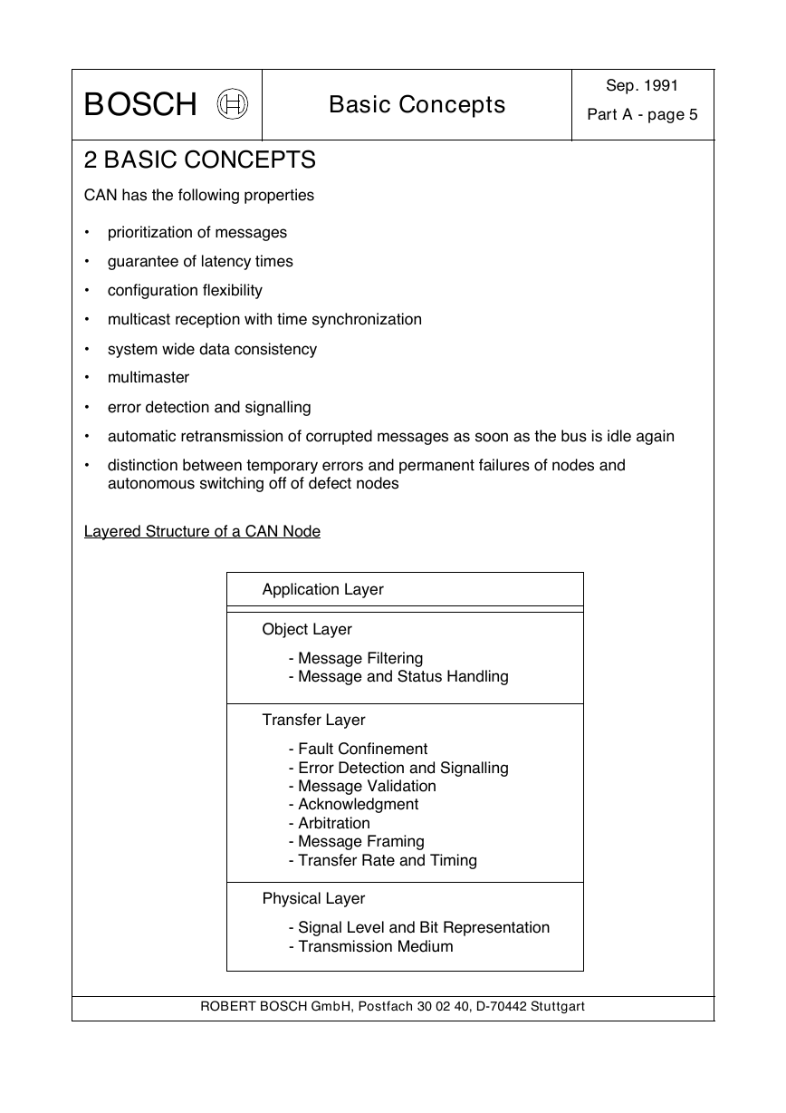
Layered Structure of a CAN Node
Application Layer
Object Layer
- Message Filtering
- Message and Status Handling
Transfer Layer
- Fault Confinement
- Error Detection and Signalling
- Message Validation
- Acknowledgment
- Arbitration
- Message Framing
- Transfer Rate and Timing
Physical Layer
- Signal Level and Bit Representation
- Transmission Medium
ROBERT BOSCH GmbH, Postfach 30 02 40, D-70442 Stuttgart
�
BOSCH
Basic Concepts
Sep. 1991
Part A - page 6
• The Physical Layer defines how signals are actually transmitted. Within this
specification the physical layer is not defined so as to allow transmission medium
and signal level implementations to be optimized for their application.
• The Transfer Layer represents the kernel of the CAN protocol. It presents
messages received to the object layer and accepts messages to be transmitted
from the object layer. The transfer layer is responsible for bit timing and
synchronization, message framing, arbitration, acknowledgment, error detection and
signalling, and fault confinement.
• The Object Layer is concerned with message filtering as well as status and
message handling.
The scope of this specification is to define the transfer layer and the consequences of
the CAN protocol on the surrounding layers.
Messages
Information on the bus is sent in fixed format messages of different but limited length
(see section 3: Message Transfer). When the bus is free any connected unit may start
to transmit a new message.
Information Routing
In CAN systems a CAN node does not make use of any information about the system
configuration (e.g. station addresses). This has several important consequences.
System Flexibility: Nodes can be added to the CAN network without requiring
any change in the software or hardware of any node and application layer.
Message Routing: The content of a message is named by an IDENTIFIER. The
IDENTIFIER does not indicate the destination of the message, but describes the
meaning of the data, so that all nodes in the network are able to decide by
MESSAGE FILTERING whether the data is to be acted upon by them or not.
Multicast: As a consequence of the concept of MESSAGE FILTERING any
number of nodes can receive and simultaneously act upon the same message.
Data Consistency: Within a CAN network it is guaranteed that a message is
simultaneously accepted either by all nodes or by no node. Thus data
consistency of a system is achieved by the concepts of multicast and by error
handling.
ROBERT BOSCH GmbH, Postfach 30 02 40, D-70442 Stuttgart
�
BOSCH
Basic Concepts
Sep. 1991
Part A - page 7
Bit rate
The speed of CAN may be different in different systems. However, in a given system
the bitrate is uniform and fixed.
Priorities
The IDENTIFIER defines a static message priority during bus access.
Remote Data Request
By sending a REMOTE FRAME a node requiring data may request another node to
send the corresponding DATA FRAME. The DATA FRAME and the corresponding
REMOTE FRAME are named by the same IDENTIFIER.
Multimaster
When the bus is free any unit may start to transmit a message. The unit with the
message of higher priority to be transmitted gains bus access.
Arbitration
Whenever the bus is free, any unit may start to transmit a message. If 2 or more units
start transmitting messages at the same time, the bus access conflict is resolved by
bitwise arbitration using the IDENTIFIER. The mechanism of arbitration guarantees that
neither information nor time is lost. If a DATA FRAME and a REMOTE FRAME with the
same IDENTIFIER are initiated at the same time, the DATA FRAME prevails over the
REMOTE FRAME. During arbitration every transmitter compares the level of the bit
transmitted with the level that is monitored on the bus. If these levels are equal the unit
may continue to send. When a ’recessive’ level is sent and a ’dominant’ level is
monitored (see Bus Values), the unit has lost arbitration and must withdraw without
sending one more bit.
Safety
In order to achieve the utmost safety of data transfer, powerful measures for error
detection, signalling and self-checking are implemented in every CAN node.
Error Detection
For detecting errors the following measures have been taken:
- Monitoring (transmitters compare the bit levels to be transmitted with the bit
levels detected on the bus)
- Cyclic Redundancy Check
- Bit Stuffing
- Message Frame Check
ROBERT BOSCH GmbH, Postfach 30 02 40, D-70442 Stuttgart
�



 uCOS-III的任务调度算法研究.pdf
 STM32F103x8B_DS_CH_V10(7STM32中文数据手册).pdf
 FX2N系列PLC培训教程.pdf
 Modbus协议资料.pdf
 WM8978中文资料(芯片资料).doc
 5-1.【Codelab】HarmonyOS基于图像模块实现图库图片的四种常见操作.pdf
 GX Developer 编程软件使用说明.pdf
 MR-E伺服与FX3G接线图.pdf
 ATK-NEO-6M GPS模块常见问题汇总_201400721.pdf
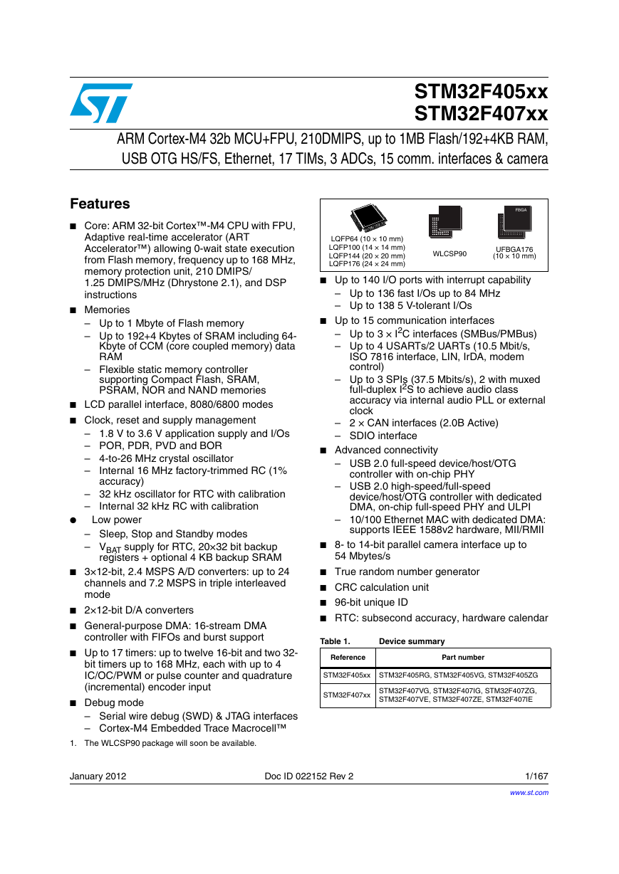 STM32F407ZGT6(芯片资料).pdf
 FM1715编程指南.pdf
 Profibus教程-7.PROFIBUS-FMS.pdf