CiA Draft Standard 401
CANopen
Device profile for generic I/O modules
Version: 3.0
03 June 2008
CAN in Automation (CiA) e. V.
�
HISTORY
Date
2002-05-17
2006-10-02
2008-06-03
Device profile for generic I/O modules
Changes
Publication of version 2.1 as draft standard
Publication of version 3.0 as draft standard proposal
- Editorial and lay-out changes have been made
- Object 1000h: Additional definitions
- Detailed definitions of PDO parameters have been included
- Additional PDO mapping for joystick devices
- Warning if analogue input global interrupt is disabled
- Additional dead-band objects for joystick devices
Publication of version 3.0 as draft standard
General information on licensing and patents
CAN in AUTOMATION (CiA) calls attention to the possibility that some of the elements of this
CiA specification may be subject of patent rights. CiA shall not be responsible for identifying
any or all such patent rights.
Because this specification is licensed free of charge, there is no warranty for this
specification, to the extent permitted by applicable law. Except when otherwise stated in
writing the copyright holder and/or other parties provide this specification “as is” without
warranty of any kind, either expressed or implied, including, but not limited to, the implied
warranties of merchantability and fitness for a particular purpose. The entire risk as to the
correctness and completeness of the specification is with you. Should this specification prove
failures, you assume the cost of all necessary servicing, repair or correction.
© CiA 2008
All rights reserved. Unless otherwise specified, no part of this publication may be reproduced or
utilized in any form or by any means, electronic or mechanical, including photocopying and microfilm,
without permission in writing from CiA at the address below.
CAN in Automation e. V.
Kontumazgarten 3
DE - 90429 Nuremberg, Germany
Tel.: +49-911-928819-0
Fax: +49-911-928819-79
Url: www.can-cia.org
Email: headquarters@can-cia.org
2
CiA 2008 – All rights reserved
�
Device profile for generic I/O modules
CONTENTS
1 Scope ...............................................................................................................................7
2 Normative references........................................................................................................7
3 Definitions and abbreviations ............................................................................................7
3.1 Definition .................................................................................................................7
3.2 Abbreviations...........................................................................................................7
4 Operating principle............................................................................................................7
4.1
Introduction .............................................................................................................7
4.2 Node-ID assignment ................................................................................................8
5 Error handling ...................................................................................................................8
5.1 Principle ..................................................................................................................8
5.2 Error behavior..........................................................................................................8
5.3 Analogue input disable warning ...............................................................................8
5.4 Additional error code definitions...............................................................................8
6 Pre-definitions...................................................................................................................9
6.1
Introduction .............................................................................................................9
6.2 Pre-defined communication objects .........................................................................9
6.2.1 Object 1000h: Device type............................................................................9
6.2.2 Object 1001h: Error register ....................................................................... 10
6.2.3 Object 1029h: Error behavior...................................................................... 10
6.2.4 RPDO 1 (digital outputs) ............................................................................ 11
6.2.5 TPDO 1 (digital inputs) .............................................................................. 13
6.2.6 RPDO 2 (analogue outputs) ....................................................................... 15
6.2.7 TPDO 2 (analogue inputs) ......................................................................... 17
6.2.8 RPDO 3 (additional analogue outputs) ....................................................... 19
6.2.9 TPDO 3 (additional analogue inputs) ......................................................... 22
6.2.10 RPDO 4 (additional analogue outputs)....................................................... 24
6.2.11 TPDO 4 (additional analogue inputs) ......................................................... 26
6.2.12 Manufacturer-specific PDOs ...................................................................... 29
7 Object dictionary ............................................................................................................. 29
Introduction ........................................................................................................... 29
Input and output function principles ....................................................................... 29
7.2.1 Object dictionary for the digital input and output modules .......................... 29
7.2.2 Digital input module ................................................................................... 30
7.2.3 Digital output module ................................................................................. 31
7.2.4 Analogue input module .............................................................................. 31
7.2.5 Analogue output module ............................................................................ 32
8 Detailed object definitions ............................................................................................... 33
8.1
Introduction ........................................................................................................... 33
8.2 Digital input module ............................................................................................... 33
8.2.1 Object 6000h: Read input 8-bit ................................................................... 33
8.2.2 Object 6002h: Polarity input 8-bit ............................................................... 35
8.2.3 Object 6003h: Filter constant input 8-bit ..................................................... 36
8.2.4 Object 6005h: Global interrupt enable digital 8-bit ...................................... 37
8.2.5 Object 6006h: Interrupt mask any change 8-bit........................................... 38
8.2.6 Object 6007h: Interrupt mask low-to-high 8-bit ........................................... 39
8.2.7 Object 6008h: Interrupt mask high-to-low 8-bit ........................................... 40
3
7.1
7.2
CiA 2008 – All rights reserved
�
Device profile for generic I/O modules
8.2.8 Object 6020h to 6027h: Read input bit 1 to 128 to read input bit 897 to
1024 .......................................................................................................... 41
8.2.9 Object 6030h to 6037h: Polarity input bit 1 to 128 to polarity input bit
897 to 1024 ............................................................................................... 43
8.2.10 Object 6038h to 603Fh: Filter constant input bit 1 to 128 to filter
constant input bit 897 to 1024.................................................................... 44
8.2.11 Object 6050h to 6057h: Interrupt mask input bit any change 1 to 128
to interrupt mask input bit any change 897 to 1024.................................... 45
8.2.12 Object 6060h to 6067h: Interrupt mask input low-to-high bit 1 to 128
to interrupt mask input low-to-high bit 897 to 1024..................................... 46
8.2.13 Object 6070h to 6077h: Interrupt mask input high-to-low bit 1 to 128
to interrupt mask input high-to-low bit 897 to 1024..................................... 47
8.2.14 Object 6100h: Read input 16-bit ................................................................. 49
8.2.15 Object 6102h: Polarity input 16-bit ............................................................. 50
8.2.16 Object 6103h: Filter constant input 16-bit ................................................... 51
8.2.17 Object 6106h: Interrupt mask input any change 16-bit ................................ 52
8.2.18 Object 6107h: Interrupt mask input low-to-high 16-bit................................. 53
8.2.19 Object 6108h: Interrupt mask input high-to-low 16-bit................................. 55
8.2.20 Object 6120h: Read input 32-bit ................................................................. 56
8.2.21 Object 6122h: Polarity input 32-bit ............................................................. 57
8.2.22 Object 6123h: Filter constant input 32-bit ................................................... 58
8.2.23 Object 6126h: Interrupt mask input any change 32-bit ................................ 59
8.2.24 Object 6127h: Interrupt mask input low-to-high 32-bit................................. 61
8.2.25 Object 6128h: Interrupt mask input high-to-low 32-bit................................. 62
8.3 Digital output module ............................................................................................. 63
8.3.1 Object 6200h: Write output 8-bit ................................................................. 63
8.3.2 Object 6202h: Change polarity output 8-bit................................................. 64
8.3.3 Object 6206h: Error mode output 8-bit........................................................ 66
8.3.4 Object 6207h: Error value output 8-bit ........................................................ 67
8.3.5 Object 6208h: Filter mask output 8-bit ........................................................ 68
8.3.6 Object 6220h to 6227h: Write output bit 1 to 128 to write output bit
897 to 1024 ............................................................................................... 69
8.3.7 Object 6240h to 6247h: Change polarity output bit 1 to 128 to change
polarity output bit 897 to 1024 ................................................................... 70
8.3.8 Object 6250h to 6257h: Error mode output lines 1 to 128 to error
mode output lines 897 to 1024................................................................... 71
8.3.9 Object 6260h to 6267h: Error value output bit 1 to 128 to error value
output bit 897 to 1024................................................................................ 73
8.3.10 Object 6270h to 6277h: Filter mask output bit 1 to 128 to filter mask
output bit 897 to 1024................................................................................ 74
8.3.11 Object 6300h: Write output 16-bit ............................................................... 75
8.3.12 Object 6302h: Change polarity output 16-bit............................................... 76
8.3.13 Object 6306h: Error mode output 16-bit...................................................... 78
8.3.14 Object 6307h: Error value output 16-bit ...................................................... 79
8.3.15 Object 6308h: Filter mask output 16-bit ...................................................... 80
8.3.16 Object 6320h: Write output 32-bit ............................................................... 81
8.3.17 Object 6322h: Change polarity output 32-bit............................................... 82
8.3.18 Object 6326h: Error mode output 32-bit...................................................... 84
8.3.19 Object 6327h: Error value output 32-bit ...................................................... 85
8.3.20 Object 6328h: Filter mask output 32-bit ...................................................... 86
8.4 Analogue input module .......................................................................................... 87
CiA 2008 – All rights reserved
4
�
Device profile for generic I/O modules
8.4.1 Object 6400h: Read analogue input 8-bit.................................................... 87
8.4.2 Object 6401h: Read analogue input 16-bit.................................................. 88
8.4.3 Object 6402h: Read analogue input 32-bit.................................................. 90
8.4.4 Object 6403h: Read analogue input float .................................................... 91
8.4.5 Object 6404h: Read manufacturer-specific analogue input ......................... 92
8.5 Analogue output module ........................................................................................ 94
8.5.1 Object 6410h: Write analogue output 8-bit.................................................. 94
8.5.2 Object 6411h: Write analogue output 16-bit................................................ 95
8.5.3 Object 6412h: Write analogue output 32-bit................................................ 96
8.5.4 Object 6413h: Write analogue output float .................................................. 97
8.5.5 Object 6414h: Write manufacturer-specific analogue output ....................... 99
8.6 Analogue input set-ups ........................................................................................ 100
8.6.1 Object 6420h............................................................................................ 100
8.6.2 Object 6421h: Analogue input interrupt trigger selection........................... 100
8.6.3 Object 6422h: Analogue input interrupt source ......................................... 101
8.6.4 Object 6423h: Analogue input global interrupt enable............................... 103
8.6.5 Object 6424h: Analogue input interrupt upper limit integer........................ 103
8.6.6 Object 6425h: Analogue input interrupt lower limit integer ........................ 104
8.6.7 Object 6426h: Analogue input interrupt delta unsigned ............................. 106
8.6.8 Object 6427h: Analogue input interrupt negative delta unsigned............... 107
8.6.9 Object 6428h: Analogue input interrupt positive delta unsigned ................ 108
8.6.10 Object 6429h: Analogue input interrupt upper limit float ........................... 109
8.6.11 Object 642Ah: Analogue input interrupt lower limit float............................ 110
8.6.12 Object 642Bh: Analogue input interrupt delta float.................................... 112
8.6.13 Object 642Ch: Analogue input interrupt negative delta float ..................... 113
8.6.14 Object 642Dh: Analogue input interrupt positive delta float....................... 114
8.6.15 Object 642Eh: Analogue input offset float................................................. 115
8.6.16 Object 642Fh: Analogue input pre-scaling float ........................................ 116
8.6.17 Object 6430h: Analogue input SI unit ....................................................... 118
8.6.18 Object 6431h: Analogue input offset integer ............................................. 119
8.6.19 Object 6432h: Analogue input pre-scaling integer..................................... 120
8.7 Analogue output set-ups ...................................................................................... 121
8.7.1 Object 6440h............................................................................................ 121
8.7.2 Object 6441h: Analogue output offset float ............................................... 121
8.7.3 Object 6442h: Analogue output scaling float............................................. 123
8.7.4 Object 6443h: Analogue output error mode .............................................. 124
8.7.5 Object 6444h: Analogue output error value integer ................................... 125
8.7.8 Object 6445h: Analogue output error value float ....................................... 126
8.7.9 Object 6446h: Analogue output offset integer ........................................... 128
8.7.10 Object 6447h: Analogue output scaling integer......................................... 129
8.7.11 Object 6450h: Analogue output SI unit ..................................................... 130
8.8 General device profile objects.............................................................................. 131
8.8.1 Object 67FFh: Device type ....................................................................... 131
Annex A : Joystick .............................................................................................................. 132
A.1 Scope........................................................................................................................... 132
A.2 Pre-defined communication objects for joysticks........................................................... 132
A.2.1 Object 1000h: Device type ................................................................................... 132
A.3 Joystick buttons............................................................................................................ 132
CiA 2008 – All rights reserved
5
�
Device profile for generic I/O modules
A.4 Joystick proportional inputs .......................................................................................... 132
A.5 Joystick PDO mappings................................................................................................ 132
A.5.1 Introduction ......................................................................................................... 132
A.5.2 1st TPDO mapping (buttons) ............................................................................... 133
A.5.3 2nd TPDO mapping (proportional inputs)............................................................. 133
A.5.4 Specific PDO mapping for 3-D joysticks............................................................... 133
A.5.5 Specific PDO mapping for 2-D joysticks............................................................... 133
A.6 Joystick signal conditioning .......................................................................................... 134
A.6.1 Introduction ......................................................................................................... 134
A.6.2 Object 6460h: Analogue input dead-band unsigned.............................................. 134
A.6.3 Object 6461h: Analogue input dead-band float ..................................................... 135
A.6.4 Object 6462h: Analogue input post-scaling unsigned ........................................... 136
A.6.5 Object 6463h: Analogue input post-scaling float................................................... 138
A.7 Joystick implementation hints ....................................................................................... 139
A.7.1 Periodical PDO transmission ............................................................................... 139
A.7.2 Additional proportional inputs .............................................................................. 139
A.7.3 Transmission of proportional inputs ..................................................................... 139
6
CiA 2008 – All rights reserved
�
1 Scope
Device profile for generic I/O modules
This specification represents the CANopen device profile for generic digital and analogue
input and output modules. Devices compliant to this specification use communication
techniques, which conform to those described in the CANopen application layer and
communication profile specification.
I/O devices may use
communication techniques, which conform to those described in the CANopen additional
application layer functions.
In addition, programmable
In the appendices, some specific I/O devices are defined.
2 Normative references
/CiA301/
CiA 301, CANopen application layer and communication profile
/CiA303-2/
CiA 303-2, CANopen additional specification – Part 2: Representation of SI
units and prefixes
/CiA305/
CiA 305, CANopen layer setting services
3 Definitions and abbreviations
3.1 Definition
The definitions given in /CiA301/ and /CiA303-2/ apply for this specification, too.
3.2 Abbreviations
CAN
CAN-ID
COB
COB-ID
I/O
PDO
RPDO
SDO
TPDO
Controller area network
CAN identifier
Communication object
COB identifier
Input and output
Process data object
Receive process data object
Service data object
Transmit process data object
4 Operating principle
4.1
Introduction
The purpose of I/O modules is to connect sensors and actuators to CANopen networks. In
NMT operational mode, input data are transmitted from the inputs via TPDOs. By default, the
PDO transmission is triggered by an interrupt (event). Optionally PDOs are transmitted
synchronously or remotely requested. In addition, it is possible to read input data via SDO
communication from another module, or to write data via SDO to the network, if the module
provides SDO client functionality.
Output data can be received via RPDO by those I/O modules that have output capabilities.
Output data also can be received via SDO communication services.
However, the main purpose of SDO communication is to configure an I/O module. The module
can receive via SDO I/O configuration data, parameters for converting data into meaningful
measurements and so on. I/O modules compliant with this device profile use pre-defined
CiA 2008 – All rights reserved
7
�
Device profile for generic I/O modules
PDOs. The default mapping of application objects into TPDO respectively RPDO is
changeable via SDO, if variable PDO mapping is supported. An I/O module provides
optionally sync producer/consumer,
time-stamp producer/consumer and emergency
producer/consumer functionality. For new designs, it is recommended to support Heartbeat
functionality.
4.2 Node-ID assignment
The node-ID assignment is manufacturer specific. If a node-ID assignment via CAN network is
required (e.g. for IP 67-rated devices), it is recommended to use the layer setting protocols as
defined in /CiA305/.
5 Error handling
5.1 Principle
Emergency messages are triggered by internal errors in the device and they are assigned the
highest possible priority to ensure that they get access to the bus without latency. By default,
the Emergency messages contain the error field with pre-defined error numbers and
additional information.
5.2 Error behavior
If a serious device failure is detected the module shall enter by default autonomously the Pre-
operational state. If 1029h object is implemented, the device may be configured to enter
alternatively the Stopped state or remain in the current state in case of a device failure.
Device failures should include the following communication errors:
• Bus-off conditions of the CAN interface
• Life guarding event with the state ‘occurred’
• Heartbeat event with state ‘occurred’
Severe device errors also may be caused by device internal failures.
5.3 Analogue input disable warning
If the CANopen device transits to NMT operational state and the Analogue input global
interrupt object (6423h) is set to FALSE, it shall transmit an Emergency message with the
error code 0080h. This Emergency message shall not cause a transition into NMT pre-
operational or NMT stopped state.
5.4 Additional error code definitions
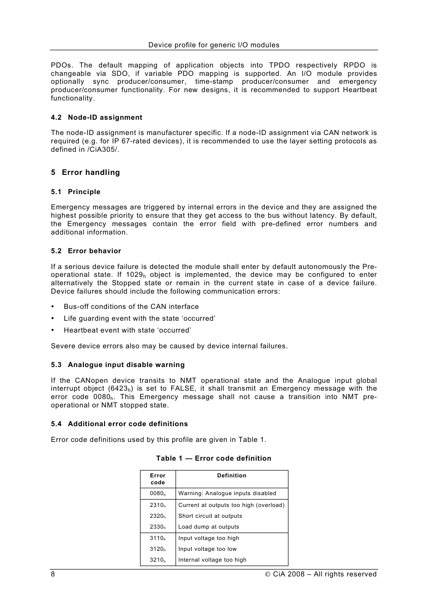
Error code definitions used by this profile are given in Table 1.
Table 1 — Error code definition
Error
code
0080h
2310h
2320h
2330h
3110h
3120h
3210h
Definition
Warning: Analogue inputs disabled
Current at outputs too high (overload)
Short circuit at outputs
Load dump at outputs
Input voltage too high
Input voltage too low
Internal voltage too high
8
CiA 2008 – All rights reserved
�
