AJ65BT-64RD3 USER MANUAL
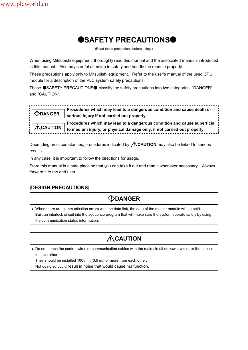
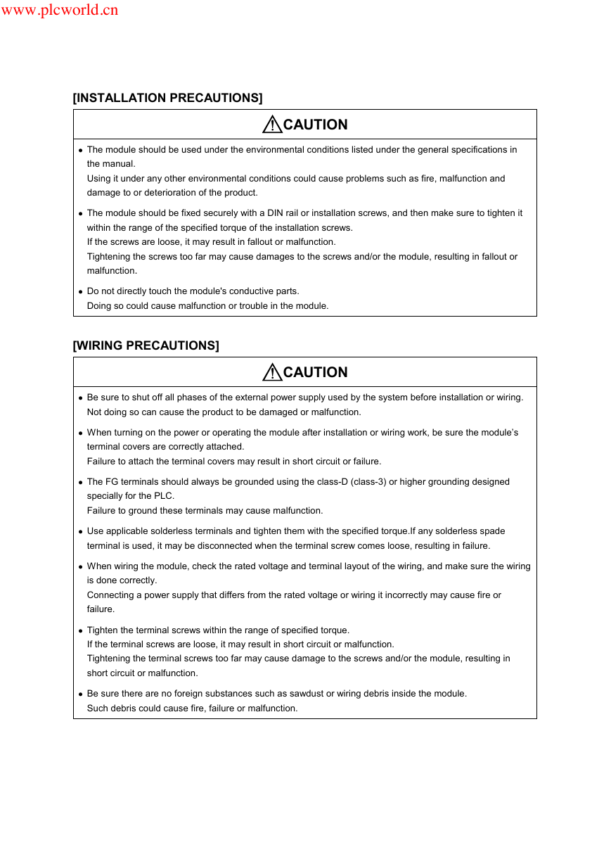
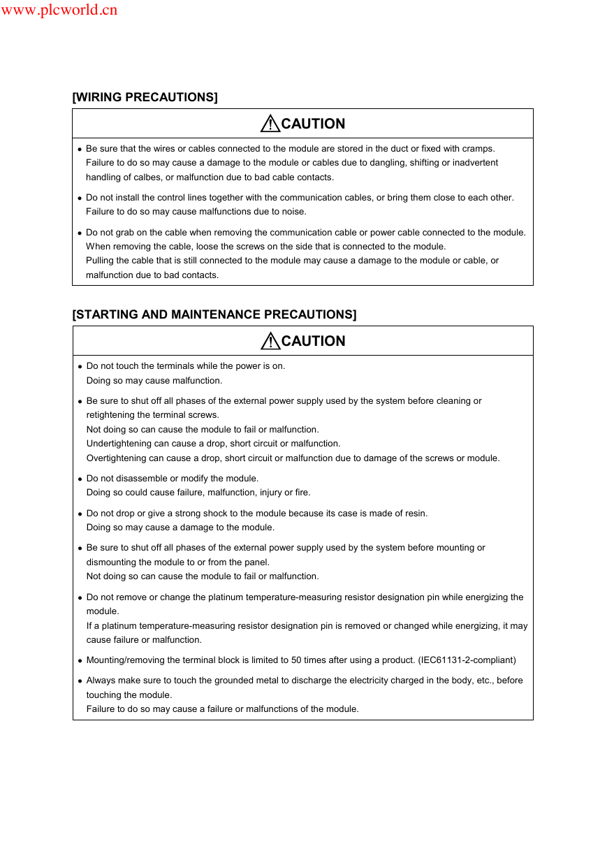
SAFETY PRECAUTIONS
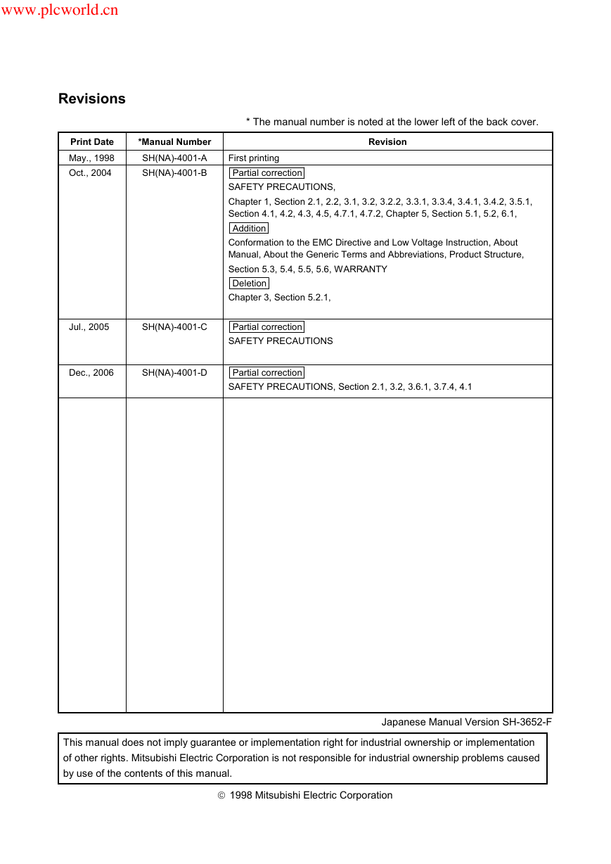
Revisions
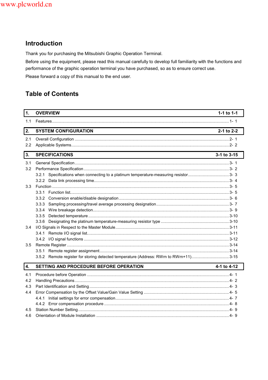
Introduction
Table of Contents
About This Manual
Conformation to the EMC Directive and Low Voltage Instruction
About Generic Terms and Abbreviations
Packing List
1. OVERVIEW
1.1 Features
2. SYSTEM CONFIGURATION
2.1 Overall Configuration
2.2 Applicable Systems
3. SPECIFICATIONS
3.1 General Specification
3.2 Performance Specification
3.2.1 Specifications when connecting to a platinum temperature-measuring resistor
3.2.2 Data link processing time
3.3 Function
3.3.1 Function list
3.3.2 Conversion enable/disable designation
3.3.3 Sampling processing/travel average processing designation
3.3.4 Wire breakage detection
3.3.5 Detected temperature
3.3.6 Designating the platinum temperature-measuring resistor type
3.4 I/O Signals in Respect to the Master Module
3.4.1 Remote I/O signal list
3.4.2 I/O signal functions
3.5 Remote Register
3.5.1 Remote register assignment
3.5.2 Remote register for storing detected temperature (Address : RWrn to RWrn+11)
4. SETTING AND PROCEDURE BEFORE OPERATION
4.1 Procedure before Operation
4.2 Handling Precautions
4.3 Part Identification and Setting
4.4 Error Compensation by the Offset Value/Gain Value Setting
4.4.1 Initial settings for error compensation
4.4.2 Error compensation procedure
4.5 Station Number Setting
4.6 Orientation of Module Installation
4.7 Wiring
4.7.1 Handling precautions for CC-Link dedicated cable
4.7.2 Wiring example with CC-Link modules
4.7.3 Precautions when wiring to a platinum temperature-measuring resistor
4.7.4 Connecting AJ65BT-64RD3 and platinum temperature-measuring resistor
4.7.5 Connecting AJ65BT-64RD and platinum temperature-measuring resistor
5. PROGRAMMING
5.1 Programming Procedure
5.2 Program Example Conditions
5.3 Program Examples when QCPU (Q Mode) Is Used
5.4 Program Examples when QnACPU Is Used
5.5 Program Example when ACPU/QCPU (A Mode) Is Used (Dedicated Instructions)
5.6 Program Example when ACPU/QCPU (A Mode) Is Used (FROM/TO Instructions)
6. TROUBLESHOOTING
6.1 Cause of Errors and Corrective Actions by LED Indication
6.2 When Wire Breakage Detection Flag is On
6.3 When E 2 PROM Error Flag is On
6.4 When Detected Temperature Value cannot be Read
6.5 When Detected Temperature Value is Abnormal
6.6 When There is a Communication Error between Master Station and AJ65BT-64RD
APPENDIX
Appendix 1 Standard Thermal Electromotive Force of Platinum Temperature-Measuring Resistor
Appendix 1.1 New JIS · IEC type (Pt100)
Appendix 1.2 Old JIS type (JPt100)
Appendix 2 External Dimensions Diagram
WARRANTY
AJ65SBT-64AD USER MANUAL
SAFETY PRECAUTIONS
REVISIONS
INTRODUCTION
CONTENTS
About Manuals
Conformation to the EMC Directive and Low Voltage Instruction
About the Generic Terms and Abbreviations
Product components
1 OVERVIEW
1.1 Features
2 SYSTEM CONFIGURATION
2.1 Overall Configuration
2.2 Applicable System
2.3 Checking Hardware Versions
3 SPECIFICATION
3.1 General Specification
3.2 Performance Specification
3.3 I/O Conversion Characteristics
3.3.1 Voltage input characteristics
3.3.2 Current input characteristics
3.3.3 Relationship between the offset/gain setting and digital output value
3.3.4 Accuracy
3.3.5 Conversion speed
3.4 Function List
3.4.1 Sampling processing
3.4.2 Moving average processing
3.5 Remote I/O Signals
3.5.1 Remote I/O signal list
3.5.2 Functions of the remote I/O signals
3.6 Remote Register
3.6.1 Remote register allocation
3.6.2 A/D conversion enable/prohibit specification (Address RWwm)
3.6.3 Input range setting (Address RWwm+1)
3.6.4 Moving average processing count setting (Address RWwm+2)
3.6.5 CH.[ ] Digital output value (Address RWrn to RWrn+3)
4 SETUP AND PREPARATION BEFORE OPERATION
4.1 Pre-Operation Procedure
4.2 Precautions When Handling
4.3 Name of Each Part
4.4 Offset/Gain Setting
4.5 Station Number Setting
4.6 Facing Direction of the Module Installation
4.7 Data Link Cable Wiring
4.7.1 Instructions for handling the CC-Link dedicated cables
4.7.2 Connection of the CC-Link dedicated cables
4.8 Wiring
4.8.1 Wiring precautions
4.8.2 Module connection example
4.9 Maintenance and Inspection
5 PROGRAMMING
5.1 Programming Procedure
5.2 Conditions of Program Example
5.3 Program Example for Use of the QCPU (Q mode)
5.4 Program Example for Use of the QnACPU
5.5 Program Example for Use of the ACPU/QCPU (A mode) (dedicated instructions)
5.6 Program Example for Use of the ACPU/QCPU (A mode) (FROM/TO instructions)
6 TROUBLESHOOTING
6.1 Using the Remote Input Signals to Check Errors
6.2 Using the LED Indications to Check Errors
6.3 When the digital output value cannot be read
6.4 Troubleshooting for the Case where the "ERR." LED of the Master Station Flickers
APPENDIX
Appendix 1 Comparison between This Product and Conventional Product
Appendix 2 External Dimensions
INDEX
WARRANTY
AJ65SBTB1-16D USER MANUAL
